JP2005291893A - Cooling device and mirror cooled sensor - Google Patents
Cooling device and mirror cooled sensor Download PDFInfo
- Publication number
- JP2005291893A JP2005291893A JP2004106730A JP2004106730A JP2005291893A JP 2005291893 A JP2005291893 A JP 2005291893A JP 2004106730 A JP2004106730 A JP 2004106730A JP 2004106730 A JP2004106730 A JP 2004106730A JP 2005291893 A JP2005291893 A JP 2005291893A
- Authority
- JP
- Japan
- Prior art keywords
- mirror
- heat
- cooling element
- cover
- thermoelectric cooling
- Prior art date
- Legal status (The legal status is an assumption and is not a legal conclusion. Google has not performed a legal analysis and makes no representation as to the accuracy of the status listed.)
- Granted
Links
Images


Landscapes
- Investigating Or Analyzing Materials Using Thermal Means (AREA)
- Investigating Or Analysing Materials By Optical Means (AREA)
Abstract
【課題】冷却性能が落ちるような置かれ方をされないようにする。
【解決手段】ヒートシンクカバー22の底面22−2の形状を円弧状とする。これにより、水平面400にヒートシンクカバー22の底面22−2を接して置かれたとき、鏡面冷却式センサ201Aの重心が不安定とされる。すなわち、水平面400にヒートシンクカバー22の底面22−2を接して置くと、鏡面冷却式センサ201Aがその姿勢を保つことができず、前後方向や左右方向に転ぶ。これにより、熱電冷却素子2が鉛直方向上側に、ヒートシンク16が鉛直方向下側にして置かれるということが自然となくなり、無意識のうちにヒートパイプ13中の熱の移動効率がよくなる方向に置かれるようになる。なお、底面22−2の形状は、半球状、台形状、三角錐状、円錐状などとしてもよい。
【選択図】 図9
An object of the present invention is to prevent the cooling performance from being lowered.
A bottom surface 22-2 of a heat sink cover 22 has an arc shape. Thus, when the bottom surface 22-2 of the heat sink cover 22 is placed in contact with the horizontal plane 400, the center of gravity of the mirror-cooled sensor 201A is unstable. That is, when the bottom surface 22-2 of the heat sink cover 22 is placed in contact with the horizontal plane 400, the mirror-cooled sensor 201A cannot maintain its posture and rolls in the front-rear direction and the left-right direction. As a result, it is not natural that the thermoelectric cooling element 2 is placed on the upper side in the vertical direction and the heat sink 16 is placed on the lower side in the vertical direction, and the heat transfer efficiency in the heat pipe 13 is unconsciously placed. It becomes like this. The shape of the bottom surface 22-2 may be hemispherical, trapezoidal, triangular pyramid, conical, or the like.
[Selection] Figure 9
Description
この発明は、一方の面が低温側、他方の面が高温側とされる熱電冷却素子を用いて被冷却部材を冷却する冷却装置および鏡面を冷却して鏡面上に生じる結露や結霜を検出する鏡面冷却式センサに関するものである。 This invention uses a thermoelectric cooling element in which one surface is a low temperature side and the other surface is a high temperature side. The present invention relates to a mirror-cooled sensor.
従来より、湿度測定法として、被測定気体の温度を低下させ、その被測定気体に含まれる水蒸気の一部を結露させたときの温度を測定することにより露点を検出する露点検出法が知られている。例えば、非特許文献1には、寒剤、冷凍機、電子冷却器などを用いて鏡を冷却し、この冷却した鏡の鏡面上の反射光の強度の変化を検出し、この時の鏡面の温度を測定することによって、被測定気体中の水分の露点を検出する鏡面冷却式露点計について説明されている。
Conventionally, as a humidity measurement method, a dew point detection method is known in which a dew point is detected by measuring the temperature when the temperature of a gas to be measured is reduced and a part of water vapor contained in the gas to be measured is condensed. ing. For example, in Non-Patent
この鏡面冷却式露点計には、利用する反射光の種類によって、2つのタイプがある。1つは、正反射光を利用する正反射光検出方式(例えば、特許文献1参照)、もう1つは、散乱光を利用する散乱光検出方式(例えば、特許文献2参照)である。 There are two types of mirror-cooled dew point meters depending on the type of reflected light used. One is a specularly reflected light detection method that uses specularly reflected light (see, for example, Patent Document 1), and the other is a scattered light detection method that uses scattered light (see, for example, Patent Document 2).
〔正反射光検出方式〕
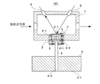
図15に正反射光検出方式を採用した従来の鏡面冷却式露点計におけるセンサ部(鏡面冷却式センサ)の構成を示す。この鏡面冷却式センサ101は、被測定気体が流入されるチャンバ1と、このチャンバ1の底部に設けられた熱電冷却素子(ペルチェ素子)2を備えている。熱電冷却素子2の冷却面2−1には鏡3が取り付けられており、熱電冷却素子2の加熱面2−2には熱伝導体(ヒートパイプ)4を介して放熱フィン5が取り付けられている。すなわち、ヒートパイプ4の一端4−1が熱電冷却素子2の加熱面2−1に取り付けられており、熱電冷却素子2から離されたヒートパイプ4の他端4−2に放熱フィン5が取り付けられている。
[Specular reflection detection method]
FIG. 15 shows the configuration of a sensor section (mirror-cooled sensor) in a conventional mirror-cooled dew point meter that employs a regular reflection light detection method. The mirror-cooled
また、熱電冷却素子2とヒートパイプ4の一端4−1にはその周囲を覆うように断熱部材6が設けられており、鏡3の上面(鏡面)3−1には温度検出素子7が取り付けられている。また、チャンバ1の上部に、鏡3の鏡面3−1に対して斜めに光を照射する発光素子8と、この発光素子8から鏡面3−1に対して照射された光の正反射光を受光する受光素子9とが設けられている。
Further, a
この鏡面冷却式センサ101において、チャンバ1内の鏡面3−1は、チャンバ1内に流入される被測定気体に晒される。鏡面3−1に結露が生じていなければ、発光素子8から照射された光はそのほゞ全量が正反射し、受光素子9で受光される。したがって、鏡面3−1に結露が生じていない場合、受光素子9で受光される反射光の強度は大きい。
In this mirror cooled
熱電冷却素子2への電流を増大し、熱電冷却素子2の冷却面2−1の温度を下げて行くと、被測定気体に含まれる水蒸気が鏡面3−1に結露し、その水の分子に発光素子8から照射した光の一部が吸収されたり、乱反射したりする。これにより、受光素子9で受光される反射光(正反射光)の強度が減少する。この鏡面3−1における正反射光の変化を検出することにより、鏡面3−1上の状態の変化、すなわち鏡面3−1上に水分(水滴)が付着したことを知ることができる。さらに、この時の鏡面3−1の温度を温度検出素子7で測定することにより、被測定気体中の水分の露点を知ることができる。
When the current to the
〔散乱光検出方式〕
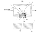
図16に散乱光検出方式を採用した従来の鏡面冷却式露点計におけるセンサ部(鏡面冷却式センサ)の構成を示す。この鏡面冷却式センサ102は、正反射光検出方式を採用した鏡面冷却式センサ101とほゞ同構成であるが、受光素子9の取り付け位置が異なっている。この鏡面冷却式センサ102において、受光素子9は、発光素子8から鏡面3−1に対して照射された光の正反射光を受光する位置ではなく、散乱光を受光する位置に設けられている。
(Scattered light detection method)
FIG. 16 shows a configuration of a sensor section (mirror-cooled sensor) in a conventional mirror-cooled dew point meter that employs the scattered light detection method. The mirror-cooled
この鏡面冷却式センサ102において、鏡面3−1は、チャンバ1内に流入される被測定気体に晒される。鏡面3−1に結露が生じていなければ、発光素子8から照射された光はそのほゞ全量が正反射し、受光素子9での受光量は極微量である。したがって、鏡面3−1に結露が生じていない場合、受光素子9で受光される反射光の強度は小さい。
In the mirror-cooled
熱電冷却素子2への電流を増大し、熱電冷却素子2の冷却面2−1の温度を下げて行くと、被測定気体に含まれる水蒸気が鏡面3−1に結露し、その水の分子に発光素子8から照射した光の一部が吸収されたり、乱反射したりする。これにより、受光素子9で受光される乱反射された光(散乱光)の強度が増大する。この鏡面3−1における散乱光の変化を検出することにより、鏡面3−1上の状態の変化、すなわち鏡面3−1上に水分(水滴)が付着したことを知ることができる。さらに、この時の鏡面3−1の温度を温度検出素子7で測定することにより、被測定気体中の水分の露点を知ることができる。
When the current to the
なお、上述した露点計においては、鏡面3−1に生じる結露(水分)を検出する例で説明したが、同様の構成によって鏡面3−1に生じる結霜(水分)を検出することも可能である。 In the dew point meter described above, the example of detecting condensation (moisture) generated on the mirror surface 3-1 has been described. However, it is also possible to detect frost (water) generated on the mirror surface 3-1 with the same configuration. is there.
図15や図16に示した鏡面冷却式センサ101や102において、露点の測定下限は熱電冷却素子2の冷却面2−1の温度を何度まで冷却できるかによって決まる。このため、この鏡面冷却式センサ101や102では、熱電冷却素子2の冷却面2−1をさらに冷却することができるように、熱電冷却素子2の加熱面2−2にヒートパイプ4の一端4−1を取り付け、熱電冷却素子2から離されたヒートパイプ4の他端4−2に放熱部材5を取り付けている。これにより、加熱面2−2に生じた熱がヒートパイプ4の一端4−1から他端4−2へと移動し、放熱部材5を通して放熱される。また、断熱部材6を設けることにより、熱電冷却素子2の加熱面2−2およびヒートパイプ4からの放熱がチャンバ1および鏡3に逆流しないようにしている。
In the mirror surface
しかしながら、上述した従来の鏡面冷却式センサ101や102は、放熱部材5の底面(端面)5−1が平坦とされているので、この底面5−1を下にして置かれやすい。すなわち、熱電冷却素子2を鉛直方向上側に、放熱部材5を鉛直方向下側にして置かれやすい。熱電冷却素子2を鉛直方向上側に、放熱部材5を鉛直方向下側にして置かれると、すなわち放熱部材5の底面5−1を水平面に接して置かれると、ヒートパイプ4中を移動する熱の移動効率が悪くなる。このため、熱電冷却素子2の冷却効率が低下し、冷却性能が落ちるという問題が生じていた。
However, since the above-described conventional mirror-cooled
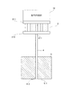
なお、特許文献3には、発熱する電子機器(例えば、CPUなど)を熱電冷却素子を利用して冷却する冷却装置が記載されている。この冷却装置では、熱電冷却素子の冷却面にCPUを取り付け、熱電冷却素子の加熱面に放熱板を取り付けている。この特許文献3に示された構成から、図17に示すように被冷却部材10を熱電冷却素子2の冷却面2−1に取り付け、熱電冷却素子2の加熱面2−2にヒートパイプ4の一端4−1を取り付け、熱電冷却素子2から離されたヒートパイプ4の他端4−2に放熱部材5を取り付けることが考えられる。このような構成においても、放熱部材5の底面5−1が平坦とされていると、熱電冷却素子2を鉛直方向上側に、放熱部材5を鉛直方向下側にして置かれやすく、ヒートパイプ4中を移動する熱の移動効率が悪くなり、冷却性能が落ちるという問題が生じる。
本発明は、このような課題を解決するためになされたもので、その目的とするところは、冷却性能が落ちるような置かれ方をされることがない冷却装置および鏡面冷却式センサを提供することにある。 The present invention has been made to solve such problems, and an object of the present invention is to provide a cooling device and a mirror-cooled sensor that are not placed in such a manner that the cooling performance is lowered. There is.
このような目的を達成するために、第1発明(請求項1に係る発明)は、一方の面が低温側、他方の面が高温側とされる熱電冷却素子と、熱電冷却素子の低温側の面に取り付けられた被冷却部材と、熱電冷却素子の高温側の面にその一端が取り付けられその他端が熱電冷却素子から離された熱伝導体と、熱伝導体の他端に取り付けられた放熱部材とを備えた冷却装置において、放熱部材の端面の形状をその端面を水平面に接して置いたときに重心を不安定とする形状としたものである。 In order to achieve such an object, the first invention (the invention according to claim 1) includes a thermoelectric cooling element in which one surface is a low temperature side and the other surface is a high temperature side, and a low temperature side of the thermoelectric cooling element. A member to be cooled attached to the surface, a heat conductor having one end attached to the surface on the high temperature side of the thermoelectric cooling element and the other end separated from the thermoelectric cooling element, and attached to the other end of the heat conductor In a cooling device provided with a heat radiating member, the shape of the end face of the heat radiating member is such that the center of gravity becomes unstable when the end face is placed in contact with a horizontal plane.
第4発明(請求項4に係る発明)は、鏡面が被測定気体に晒される鏡と、鏡の鏡面とは反対側の面に低温側の面が取り付けられた熱電冷却素子と、鏡の鏡面に対して光を照射する発光手段と、発光手段から鏡面に対して照射された光の反射光を受光する受光手段と、熱電冷却素子の高温側の面にその一端が取り付けられその他端が熱電冷却素子から離された熱伝導体と、熱伝導体の他端に取り付けられた放熱部材とを備えた鏡面冷却式センサにおいて、放熱部材の端面の形状をその端面を水平面に接して置いたときに重心を不安定とする形状としたものである。 A fourth invention (invention according to claim 4) includes a mirror whose mirror surface is exposed to the gas to be measured, a thermoelectric cooling element in which a low temperature side surface is attached to a surface opposite to the mirror surface of the mirror, and the mirror surface of the mirror A light emitting means for irradiating light, a light receiving means for receiving reflected light of the light emitted from the light emitting means to the mirror surface, and one end of the thermoelectric cooling element attached to the high temperature side surface, and the other end being a thermoelectric In a mirror-cooled sensor having a heat conductor separated from the cooling element and a heat radiating member attached to the other end of the heat conductor, the shape of the end face of the heat radiating member is placed in contact with the horizontal plane. The center of gravity is unstable.
この第1および第4発明によれば、放熱部材の端面の形状が例えば半球状、台形状、三角錐状、円錐状などとされ、水平面に放熱部材の端面を接して置いたときの重心が不安定とされる。これにより、熱電冷却素子を鉛直方向上側に、放熱部材を鉛直方向下側にして置かれるということが自然となくなり、無意識のうちに熱伝導体(ヒートパイプ)中の熱の移動効率がよくなる方向に置かれるようになる。 According to the first and fourth inventions, the shape of the end surface of the heat dissipation member is, for example, hemispherical, trapezoidal, triangular pyramid, conical, etc., and the center of gravity when the end surface of the heat dissipation member is placed in contact with the horizontal plane is It is considered unstable. This naturally eliminates the fact that the thermoelectric cooling element is placed on the upper side in the vertical direction and the heat dissipating member is placed on the lower side in the vertical direction, and the direction in which heat transfer efficiency in the heat conductor (heat pipe) is improved unconsciously. Will be put on.
第2発明(請求項2に係る発明)は、一方の面が低温側、他方の面が高温側とされる熱電冷却素子と、熱電冷却素子の低温側の面に取り付けられた被冷却部材と、熱電冷却素子の高温側の面にその一端が取り付けられその他端が熱電冷却素子から離された熱伝導体と、熱伝導体の一端と他端との間に設けられた保持部材と、熱伝導体の他端に取り付けられた放熱部材と、放熱部材とこの放熱部材から保持部材までの熱伝導体を覆うカバーとを備えた冷却装置において、カバーの端面の形状をその端面を水平面に接して置いたときに重心を不安定とする形状とし、カバーの放熱部材と対向する周壁に通気孔を形成したものである。 The second invention (the invention according to claim 2) is a thermoelectric cooling element in which one surface is a low temperature side and the other surface is a high temperature side, and a member to be cooled attached to a low temperature side surface of the thermoelectric cooling element; A heat conductor having one end attached to the high temperature side surface of the thermoelectric cooling element and the other end separated from the thermoelectric cooling element, a holding member provided between one end and the other end of the heat conductor, In a cooling device comprising a heat radiating member attached to the other end of the conductor, a heat radiating member and a cover covering the heat conductor from the heat radiating member to the holding member, the shape of the end face of the cover is in contact with the horizontal plane. The center of gravity of the cover is unstable and the vent hole is formed in the peripheral wall of the cover facing the heat radiating member.
第5発明(請求項5に係る発明)は、鏡面が被測定気体に晒される鏡と、鏡の鏡面とは反対側の面に低温側の面が取り付けられた熱電冷却素子と、鏡の鏡面に対して光を照射する発光手段と、発光手段から鏡面に対して照射された光の反射光を受光する受光手段と、熱電冷却素子の高温側の面にその一端が取り付けられその他端が熱電冷却素子から離された熱伝導体と、熱伝導体の一端と他端との間に設けられた保持部材と、熱伝導体の他端に取り付けられた放熱部材と、放熱部材とこの放熱部材から保持部材までの熱伝導体を覆うカバーとを備えた鏡面冷却式センサにおいて、カバーの端面の形状をその端面を水平面に接して置いたときに重心を不安定とする形状とし、カバー放熱部材と対向する周壁に通気孔を形成したものである。 A fifth invention (invention according to claim 5) includes a mirror whose mirror surface is exposed to the gas to be measured, a thermoelectric cooling element in which a low-temperature side surface is attached to the surface opposite to the mirror surface of the mirror, and the mirror surface of the mirror A light emitting means for irradiating light, a light receiving means for receiving reflected light of the light emitted from the light emitting means to the mirror surface, and one end of the thermoelectric cooling element attached to the high temperature side surface, and the other end being a thermoelectric A heat conductor separated from the cooling element, a holding member provided between one end and the other end of the heat conductor, a heat radiating member attached to the other end of the heat conductor, a heat radiating member, and the heat radiating member In a mirror-cooled sensor having a cover covering the heat conductor from the holding member to the holding member, the shape of the end surface of the cover is made unstable so that the center of gravity becomes unstable when the end surface is placed in contact with a horizontal surface. Ventilation holes are formed in the peripheral wall opposite to.
この第2および第5発明によれば、カバーの端面の形状が例えば円弧状、半球状、台形状、三角錐状、円錐状などとされ、水平面にカバーの端面を接して置いたときの重心が不安定とされる。これにより、熱電冷却素子を鉛直方向上側に、放熱部材を鉛直方向下側にして置かれるということが自然となくなり、無意識のうちに熱伝導体(ヒートパイプ)中の熱の移動効率がよくなる方向に置かれるようになる。また、カバーの放熱部材と対向する周壁に通気孔が形成されているので、この通気孔を介してカバー内に冷たい空気が自然に引き込まれ、またカバー内の暖かい空気が自然に排出され、カバー内の放熱部材が自然冷却される。 According to the second and fifth aspects of the invention, the shape of the end face of the cover is, for example, an arc shape, a hemispherical shape, a trapezoidal shape, a triangular pyramid shape, a conical shape, and the center of gravity when the end face of the cover is placed in contact with a horizontal plane Is considered unstable. As a result, it is not natural that the thermoelectric cooling element is placed on the upper side in the vertical direction and the heat dissipation member is placed on the lower side in the vertical direction, and the direction in which heat transfer efficiency in the heat conductor (heat pipe) is improved unconsciously. Will be put on. Further, since a vent hole is formed in the peripheral wall facing the heat radiating member of the cover, cold air is naturally drawn into the cover through this vent hole, and warm air in the cover is naturally discharged, and the cover The inside heat dissipation member is naturally cooled.
第3発明(請求項3に係る発明)は、一方の面が低温側、他方の面が高温側とされる熱電冷却素子と、熱電冷却素子の低温側の面に取り付けられた被冷却部材と、熱電冷却素子の高温側の面にその一端が取り付けられその他端が熱電冷却素子から離された熱伝導体と、熱伝導体の一端と他端との間に設けられた保持部材と、熱伝導体の他端に取り付けられた放熱部材と、放熱部材とこの放熱部材から保持部材までの熱伝導体を覆うカバーとを備えた冷却装置において、カバーの端面の形状をその端面を水平面に接して置いたときに重心を不安定とする形状とし、カバーの端面および保持部材と放熱部材との間の周壁に通気孔を形成し、カバー内にファンを設けたものである。 The third invention (the invention according to claim 3) is a thermoelectric cooling element in which one surface is a low temperature side and the other surface is a high temperature side, and a member to be cooled attached to a low temperature side surface of the thermoelectric cooling element; A heat conductor having one end attached to the high temperature side surface of the thermoelectric cooling element and the other end separated from the thermoelectric cooling element, a holding member provided between one end and the other end of the heat conductor, In a cooling device comprising a heat radiating member attached to the other end of the conductor, a heat radiating member and a cover covering the heat conductor from the heat radiating member to the holding member, the shape of the end face of the cover is in contact with the horizontal plane. The center of gravity of the cover is unstable, the vent hole is formed in the end wall of the cover and the peripheral wall between the holding member and the heat radiating member, and the fan is provided in the cover.
第6発明(請求項6に係る発明)は、鏡面が被測定気体に晒される鏡と、鏡の鏡面とは反対側の面に低温側の面が取り付けられた熱電冷却素子と、鏡の鏡面に対して光を照射する発光手段と、発光手段から鏡面に対して照射された光の反射光を受光する受光手段と、熱電冷却素子の高温側の面にその一端が取り付けられその他端が熱電冷却素子から離された熱伝導体と、熱伝導体の一端と他端との間に設けられた保持部材と、熱伝導体の他端に取り付けられた放熱部材と、放熱部材とこの放熱部材から保持部材までの熱伝導体を覆うカバーとを備えた鏡面冷却式センサにおいて、カバーの端面の形状をその端面を水平面に接して置いたときに重心を不安定とする形状とし、カバーの端面および保持部材と放熱部材との間の周壁に通気孔を形成し、カバー内にファンを設けたものである。 A sixth invention (invention according to claim 6) includes a mirror whose mirror surface is exposed to the gas to be measured, a thermoelectric cooling element in which a low-temperature side surface is attached to a surface opposite to the mirror surface of the mirror, and the mirror surface of the mirror A light emitting means for irradiating light, a light receiving means for receiving reflected light of the light emitted from the light emitting means to the mirror surface, and one end of the thermoelectric cooling element attached to the high temperature side surface, and the other end being a thermoelectric A heat conductor separated from the cooling element, a holding member provided between one end and the other end of the heat conductor, a heat radiating member attached to the other end of the heat conductor, a heat radiating member, and the heat radiating member In a mirror-cooled sensor having a cover covering the heat conductor from the holding member to the holding member, the end surface of the cover is shaped to make the center of gravity unstable when the end surface is placed in contact with a horizontal surface, and the end surface of the cover And vents in the peripheral wall between the holding member and the heat dissipation member , It is provided with a fan in the cover.
この第3および第6発明によれば、カバーの端面の形状が例えば円弧状、半球状、台形状、三角錐状、円錐状などとされ、水平面にカバーの端面を接して置いたときの重心が不安定とされる。これにより、熱電冷却素子を鉛直方向上側に、放熱部材を鉛直方向下側にして置かれるということが自然となくなり、無意識のうちに熱伝導体(ヒートパイプ)中の熱の移動効率がよくなる方向に置かれるようになる。また、カバーの端面および保持部材と放熱部材との間の周壁に通気孔が形成されており、カバー内にファンが設けられているので、ファンの回転によって通気孔を介してカバー内に冷たい空気が強制的に引き込まれ、またカバー内の暖かい空気が強制的に排出され、カバー内の放熱部材が強制冷却される。また、カバーの端面は水平面に接して置かれにくいので、その端面に形成されている通気孔が塞がれてしまうということはない。なお、この発明において、カバー内にはそのカバーの端面と放熱部材との間に空スペースを生じさせることができるので、この空スペースにファンを設けるとよい。 According to the third and sixth aspects of the invention, the shape of the end surface of the cover is, for example, an arc shape, a hemispherical shape, a trapezoidal shape, a triangular pyramid shape, a conical shape, and the center of gravity when the end surface of the cover is placed in contact with a horizontal plane Is considered unstable. This naturally eliminates the fact that the thermoelectric cooling element is placed on the upper side in the vertical direction and the heat dissipating member is placed on the lower side in the vertical direction, and the direction in which heat transfer efficiency in the heat conductor (heat pipe) is improved unconsciously. Will be put on. In addition, since the vent hole is formed in the end face of the cover and the peripheral wall between the holding member and the heat radiating member, and the fan is provided in the cover, the air that is cooled in the cover through the vent hole by the rotation of the fan. Is forcibly drawn in, the warm air in the cover is forcibly discharged, and the heat radiating member in the cover is forcibly cooled. Further, since the end face of the cover is difficult to be placed in contact with the horizontal plane, the vent hole formed in the end face is not blocked. In the present invention, since an empty space can be generated in the cover between the end surface of the cover and the heat radiating member, a fan may be provided in this empty space.
第1および第4発明によれば、放熱部材の端面の形状をその端面を水平面に接して置いたときに重心を不安定とする形状としたので、熱電冷却素子を鉛直方向上側に、放熱部材を鉛直方向下側にして置かれるということが自然となくなり、無意識のうちに熱伝導体中の熱の移動効率がよくなる方向に置かれるようになり、冷却性能が落ちるような置かれ方をされることがなくなる。 According to the first and fourth inventions, since the shape of the end face of the heat radiating member is such that the center of gravity becomes unstable when the end face is placed in contact with a horizontal plane, the thermoelectric cooling element is placed vertically above the heat radiating member. Is placed in the direction where the heat transfer efficiency in the heat conductor is improved, and the cooling performance is lowered. It will not be.
第2および第5発明によれば、カバーの端面の形状をその端面を水平面に接して置いたときに重心を不安定とする形状とし、カバーの放熱部材と対向する周壁に通気孔を形成したので、この通気孔を介してカバー内に冷たい空気が自然に引き込まれ、またカバー内の暖かい空気が自然に排出され、第1および第4発明の効果に加え、放熱部材とこの放熱部材から保持部材までの熱伝導体を保護することができると同時に、カバー内の放熱部材を自然冷却することができるようになる。 According to the second and fifth inventions, the shape of the end face of the cover is made unstable when the end face is placed in contact with a horizontal plane, and the vent hole is formed in the peripheral wall facing the heat radiating member of the cover. Therefore, cold air is naturally drawn into the cover through this vent hole, and warm air in the cover is naturally discharged, and in addition to the effects of the first and fourth inventions, the heat radiating member and the heat radiating member are retained. The heat conductor up to the member can be protected, and at the same time, the heat dissipating member in the cover can be naturally cooled.
第3および第6発明によれば、カバーの端面の形状をその端面を水平面に接して置いたときに重心を不安定とする形状とし、カバーの端面および保持部材と放熱部材との間の周壁に通気孔を形成し、カバー内にファンを設けたので、ファンの回転によって通気孔を介してカバー内に冷たい空気が強制的に引き込まれ、またカバー内の暖かい空気が強制的に排出され、第1および第4発明の効果に加え、放熱部材とこの放熱部材から保持部材までの熱伝導体を保護することができると同時に、カバー内の放熱部材を強制冷却することができるようになる。この強制冷却によって、放熱効率が向上し、冷却性能をより高めることができるようになる。また、急速に冷却することができるので、露点温度などの測定時間を短縮することができるようになる。 According to the third and sixth inventions, the shape of the end surface of the cover is such that the center of gravity becomes unstable when the end surface is placed in contact with a horizontal plane, and the peripheral surface between the end surface of the cover and the holding member and the heat dissipation member The air vent is formed in the cover and the fan is provided in the cover, so that the cold air is forcibly drawn into the cover through the air hole by the rotation of the fan, and the warm air in the cover is forcibly discharged. In addition to the effects of the first and fourth inventions, the heat radiating member and the heat conductor from the heat radiating member to the holding member can be protected, and at the same time, the heat radiating member in the cover can be forcibly cooled. By this forced cooling, the heat radiation efficiency is improved and the cooling performance can be further enhanced. Moreover, since it can cool rapidly, measurement time, such as a dew point temperature, can be shortened.
以下、本発明を図面に基づいて詳細に説明する。
〔実施の形態1:鏡面冷却式露点計(ファン有り)〕
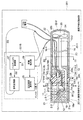
図1はこの発明に係る鏡面冷却式センサの一実施の形態を用いた鏡面冷却式露点計の概略構成図である。この鏡面冷却式露点計201はセンサ部(鏡面冷却式センサ)201Aとコントロール部201Bとを有している。
Hereinafter, the present invention will be described in detail with reference to the drawings.
[Embodiment 1: Mirror surface dew point meter (with fan)]
FIG. 1 is a schematic configuration diagram of a mirror-cooled dew point meter using an embodiment of a mirror-cooled sensor according to the present invention. The mirror-cooled
鏡面冷却式センサ201Aにおいて、熱電冷却素子(ペルチェ素子)2の冷却面2−1には鏡11が取り付けられている。鏡11は、例えばシリコンチップとされ、その表面11−1が鏡面とされている。また、鏡11と熱電冷却素子2の冷却面2−1との間には、例えば白金による薄膜測温抵抗体(温度検出素子)12が形成されている。また、熱電冷却素子2の加熱面2−2にはヒートパイプ(熱伝導体)13の一端13−1が取り付けられ、ヒートパイプ13の他端13−2は熱電冷却素子2から離されている。なお、図1では省略しているが、鏡11と一体とされた熱電冷却素子2はヒートパイプ13の一端13−1に対して着脱可能に設けられている。
In the mirror surface cooling
ヒートパイプ13は、密閉容器内に少量の液体(作動液)を真空封入したもので、内壁に毛細管構造を備えている。ヒートパイプ13の一部が加熱されると、加熱部で作動液が蒸発(蒸発潜熱の吸収)し、低温部に蒸気が移動し、この蒸気が低温部で凝縮(蒸発潜熱の放出)し、凝縮した液が毛細管現象で加熱部に環流するという一連の相変化が連続的に生じ、加熱部から低温部へと素早く熱が移動する。
The
この実施の形態において、ヒートパイプ13の一端13−1は30゜〜45゜の傾斜で立ち上げられ、この斜めに立ち上げられたヒートパイプ13の一端13−1の上面に熱電冷却素子2が取り付けられている。したがって、熱電冷却素子2の冷却面2−1に取り付けられた鏡1−1の鏡面11−1も30゜〜45゜の角度で傾けられている。
In this embodiment, one end 13-1 of the
また、ヒートパイプ13の一端(加熱部)13−1と他端(低温部)13−2との間には、一端13−1側の直線部13−3に保持部材14が設けられている。保持部材14は、ヒートパイプ13の熱伝導方向に垂直な方向(図1の上下方向)に分割可能な第1の保持部材14−1と第2の保持部材14−2とによって構成され(図2(図1におけるII−II線断面図)参照)、第1の保持部材14−1と第2の保持部材14−2との間にヒートパイプ13が挟まれている。また、第1の保持部材14−1と第2の保持部材14−2とはネジ15によって結合されており、これによってヒートパイプ13が第1の保持部材14−1と第2の保持部材14−2との間にその位置(前後方向、回転方向)を調整可能に固定されている。
Moreover, the holding
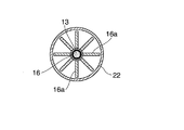
ヒートパイプ13の他端13−2にはヒートシンク16が取り付けられている。ヒートシンク16は、図3に図1におけるIII −III 線断面図を示すように、その軸心より放射状に延びた複数のフィン16aを有している。なお、ヒートパイプ13の他端13−2は、直線部13−3をそのまま延長させたものではなく、直線部13−3の途中を一端13−1の立ち上げ方向にほゞ直角に曲げた後、直線部13−3とほゞ平行に延長させたものであり、ヒートシンク16の軸心を貫通させている。
A
保持部材14は、上述したように第1の保持部材14−1と第2の保持部材14−2とによって構成されており、第1の保持部材14−1と第2の保持部材14−2との間にヒートパイプ13が位置している。この実施の形態において、第2の保持部材14−2には、熱電冷却素子2へのリード線17と投受光同軸の光ファイバ18が貫通して設けられ、光ファイバ18の先端面18aが鏡面11−1に向けられている。この結果、光ファイバ18からの光の照射方向(発光側の光軸)と光の受光方向(受光側の光軸)とが平行とされ、また隣接して同一の傾斜角とされる。
As described above, the holding
熱電冷却素子2へのリード線17は、熱電冷却素子2への電流供給用のリード線と、温度検出素子12からの信号導出用のリード線とからなり、保持部材14−2に形成された貫通孔14−2aを通されている。光ファイバ18は、その光軸がヒートパイプ13の直線部13−3とほゞ平行とされている。すなわち、この実施の形態において、ヒートパイプ13の一端13−1から他端13−2へ向かう熱の伝導路は、光ファイバ18の光軸に沿ってほゞ平行とされている。換言すると、ヒートパイプ13は、その一端13−1から他端13−2へ向かう熱の伝導路が光ファイバ18の光軸に沿ってほゞ平行となるようにその形状が定められている。
The
また、光ファイバ18は、その光軸方向への位置を調整可能に保持部材14−2に取り付けられている。この例では、光ファイバ18の根元部の周面に位置調整用のネジ部(雄ねじ部)18bが形成されており、このネジ部18bを保持部材14−2の貫通孔14−2bの入口に形成されたネジ部(雌ねじ部)14−2cに螺合することにより、光ファイバ18の先端面18aの鏡面11−1に対する位置(光軸方向の位置)を微調整することができるようにしている。
The
この鏡面冷却式センサ201Aにおいて、保持部材14を挾んで対向する熱電冷却素子2側を検知部19、ヒートシンク16側を放熱部20とした場合、検知部19には有底円筒状のミラーカバー21が取り付けられており、放熱部20には有底円筒状のヒートーシンクカバー22が取り付けられている。
In this mirror-cooled
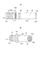
ミラーカバー21は、熱伝導が良い材質とされ、その周囲に通気孔21aが複数開設されている(図4参照)。また、ミラーカバー21の検知部19への取り付けは、ミラーカバー21の内壁面下端に形成されたネジ部21bを保持部材14の一方の端側の周縁に形成されたネジ部14aに螺合することにより行われている。
The
なお、ミラーカバー21が熱伝導が良い材質とされている理由は次のことによる。すなわち、検知部19は被測定気体内に入れられるので、被測定気体が低温低湿から高温高湿に変化したときに、ミラーカバー21が熱伝導が悪いとそのカバーに結露してしまい、正確な水分量の計測ができなくなってしまう。また、被測定気体が高湿の場合の測定時にはミラーカバーが結露しないように全体をヒーティングする必要があるが、その場合にも均一に温めるために熱伝導が良い材質であることが望まれる。
The reason why the
ヒートシンクカバー22は、保持部材14とヒートシンク16との間の空間に対向する外周面22−1の周壁に通気孔22aが複数開設されている。また、ヒートシンクカバー2の底面(端面)22−2にも通気孔22bが複数開設されている。ヒートシンクカバー22の底面22−2は、円弧状の曲面とされ、外方に突出している。また、ヒートシンクカバー22の放熱部20への取り付けは、ヒートシンクカバー22の内壁面下端に形成されたネジ部22cを保持部材14の他方の端側の周縁に形成されたネジ部14bに螺合することにより行われている。
The
この鏡面冷却式センサ201Aにおいて、ヒートシンクカバー22内には、そのヒートシンクカバー22の底面22−2とヒートシンク16との間に空スペース23が生じる。本実施の形態では、この空きスペース23にファン24を設けている。ヒートシンクカバー22の機能は、ヒートパイプ13やヒートシンク16などを保護することと、ファン24による風をまんべんなくヒートシンク16に通すことであり、したがってヒートシンクカバー22の材質は熱伝導が良い材質でなくてもよい。
In the mirror surface cooling
本実施の形態において、ヒートシンクカバー22はヒートシンク16に接触してはおらず、ヒートシンクカバー22とヒートシンク16との間に僅かな隙間が設けられている。また、ヒートシンクカバー22を放熱部20に取り付けた状態において、ヒートシンク16の軸心とファン24の回転中心とは一致した状態にある。
In the present embodiment, the
また、本実施の形態において、保持部材14の中央部14cには、その外周にネジ部14dとフランジ部14eが形成されている。ネジ部14dとフランジ部14eとは、ミラーカバー21とヒートシンクカバー22との突き合わせ部(検知部19と放熱部20との境界部)に位置し、外面に露出している。ネジ部14dはミラーカバー21やヒートシンクカバー22の外周面とほゞ同位置にあり、フランジ部14eはミラーカバー21やヒートシンクカバー22の外周面よりもその鍔面が突出している。
In the present embodiment, a
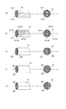
なお、本実施の形態において、光ファイバ18としては図5に示すような種々の光ファイバを使用することができる。図5(a)では、光ファイバ18中に、発光側の光ファイバ18−1と受光側の光ファイバ18−2とを同軸に設けている。図5(b)では、光ファイバ18中に、発光側(あるいは受光側)の光ファイバ18−1と受光側(あるいは発光側)の光ファイバ18−21〜18−24を同軸に設けている。図5(c)では、光ファイバ18中の左半分を発光側の光ファイバ18A、右半分を受光側の光ファイバ18Bとしている。図5(d)では、光ファイバ18中に、発光側の光ファイバ18Cと受光側の光ファイバ18Dとを混在させている。図5(e)では、光ファイバ18中の中心部を発光側(あるいは受光側)の光ファイバ18E、光ファイバ18Eの周囲を受光側(あるいは発光側)の光ファイバ18Fとしている。
In the present embodiment, various optical fibers as shown in FIG. 5 can be used as the
コントロール部201Bには、露点温度表示部25と、結露検知部26と、ペルチェ出力制御部27と、信号変換部28とが設けられている。露点温度表示部25には温度検出素子12が検出する鏡11の温度が表示される。結露検知部26は、光ファイバ18の先端部より鏡11の鏡面11−1に対して所定の周期でパルス光を照射させるとともに、光ファイバ18を介して受光される反射パルス光(散乱光)の上限値と下限値との差を反射パルス光の強度として求め、反射パルス光の強度に応じた信号S1をペルチェ出力制御部27へ送る。ペルチェ出力制御部27は、結露検知部26からの信号S1を受けて、反射パルス光の強度と予め定められている閾値とを比較し、反射パルス光の強度が閾値に達していない場合には、熱電冷却素子2への電流を信号S1の値に応じて増大させる制御信号S2を、反射パルス光の強度が閾値を超えている場合には、熱電冷却素子2への電流を信号S1の値に応じて減少させる制御信号S2を信号変換部28へ出力する。信号変換部28は、ペルチェ出力制御部27からの制御信号S2で指示される電流S3を熱電冷却素子2へ供給する。
The
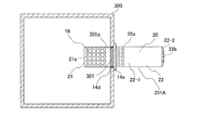
この鏡面冷却式露点計201において、例えばダクト内を流れる被測定気体中の水分の露点を検出する場合、鏡面冷却式センサ201Aは図6に示すような形でダクト300に取り付けられる。すなわち、ダクト300の外から、このダクト300の側面に開設された取り付け孔301に検知部19を挿入する。そして、保持部材14の中央部14cに形成されたネジ部14dをダクト300の取り付け孔301に形成されたネジ部301aに螺合し、フランジ部14eの鍔がダクト300の側面に当たるまで締め付ける。
In this specular cooling type
これにより、鏡面冷却式センサ201Aをダクト300に取り付けた状態において、検知部19がダクト300内に位置し、放熱部20がダクト300の外に位置する。また、ミラーカバー21の通気孔21aを介して検知部19の内部にダクト300を流れる被測定気体が入り込み、鏡11の鏡面11−1が被測定気体に晒される。また、この被測定気体に晒される状態において、検知部19の熱電冷却素子2や鏡11は、ミラーカバー21によって保護される。
Thereby, in the state which attached mirror
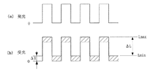
この鏡面冷却式センサ201Aのダクト300への取り付け状態において、結露検知部26は、光ファイバ18の先端部より、鏡11の鏡面11−1に対して所定の周期でパルス光を照射させる(図7(a)参照)。鏡面11−1は被測定気体に晒されており、鏡面11−1に結露が生じていなければ、光ファイバ18の先端部から照射されたパルス光はそのほゞ全量が正反射し、光ファイバ18を介して受光される鏡面11−1からの反射パルス光(散乱光)の量は極微量である。したがって、鏡面11−1に結露が生じていない場合、光ファイバ18を介して受光される反射パルス光の強度は小さい。
In the attachment state of the mirror-cooled
結露検知部26では、光ファイバ18を介して受光される反射パルス光の上限値と下限値との差を反射パルス光の強度として求め、反射パルス光の強度に応じた信号S1をペルチェ出力制御部27へ送る。この場合、反射パルス光の強度はほゞ零であり、予め定められている閾値に達していないので、ペルチェ出力制御部27は、熱電冷却素子2への電流を増大させる制御信号S2を信号変換部28へ送る。これにより、信号変換部28からの熱電冷却素子2への電流S3が増大し、熱電冷却素子2の冷却面2−1の温度が下げられて行く。
In the dew
熱電冷却素子2の冷却面2−1の温度、すなわち鏡11の温度を下げて行くと、被測定気体に含まれる水蒸気が鏡11の鏡面11−1に結露し、その水の分子に光ファイバ18の先端部から照射されたパルス光の一部が吸収されたり、乱反射したりする。これにより、光ファイバ18を介して受光される鏡面11−1からの反射パルス光(散乱光)の強度が増大する。
When the temperature of the cooling surface 2-1 of the
結露検知部26は、受光される反射パルス光の1パルス毎に、その1パルスの上限値と下限値との差を求め、これを反射パルス光の強度とする。すなわち、図7(b)に示すように、反射パルス光の1パルスの上限値Lmaxと下限値Lminとの差ΔLを求め、このΔLを反射パルス光の強度とする。この結露検知部26での処理により、反射パルス光に含まれる外乱光ΔXが除去され、外乱光による誤動作が防止される。この結露検知部26でのパルス光を用いた外乱光による誤動作防止の処理方式をパルス変調方式と呼ぶ。この処理によって、この鏡面冷却式露点計201では、鏡面冷却式センサ201Aから光の遮光を目的とするチャンバをなくすことができている。
The dew
ここで、光ファイバ18を介して受光される反射パルス光の強度が閾値を超えると、ペルチェ出力制御部27は、熱電冷却素子2への電流を減少させる制御信号S2を信号変換部28へ送る。これにより、熱電冷却素子2の冷却面2−1の温度の低下が抑えられ、結露の発生が抑制される。この結露の抑制により、光ファイバ18を介して受光される反射パルス光の強度が小さくなり、閾値を下回ると、ペルチェ出力制御部27から熱電冷却素子2への電流を増大させる制御信号S2が信号変換部28へ送られる。この動作の繰り返しによって、光ファイバ18を介して受光される反射パルス光の強度が閾値とほゞ等しくなるように、熱電冷却素子2の冷却面2−1の温度が調整される。この調整された温度、すなわち鏡面11−1に生じた結露が平衡状態に達した温度(露点温度)が、露点温度として露点温度表示部25に表示される。
Here, when the intensity of the reflected pulse light received through the
なお、この実施の形態では、鏡面11−1に生じる結露(水分)を検出するものとしたが、同様の構成によって鏡面11−1に生じる結霜(水分)を検出することも可能である。 In this embodiment, the condensation (moisture) generated on the mirror surface 11-1 is detected. However, it is also possible to detect frost (water) generated on the mirror surface 11-1 with the same configuration.
この露点の検出動作において、鏡面冷却式センサ201Aでは、熱電冷却素子2の冷却面2−1の温度が下げられると、加熱面2−2の温度が上がり、ヒートパイプ13の一端13−1が加熱される。ヒートパイプ13の一端13−1が加熱されると、この加熱された一端13−1で作動液が蒸発し、低温側の他端13−2に蒸気が移動し、この蒸気が他端13−2で凝縮し、凝縮した液が毛細管現象で一端13−1に環流するという一連の相変化が連続的に生じ、ヒートパイプ13の一端13−1から他端13−2へ素早く熱が移動する。この他端13−2に移動してきた熱はヒートシンク16を通して放熱される。
In this dew point detection operation, in the mirror surface cooling
ここで、ヒートシンクカバー22には、保持部材14とヒートシンク16との間の空間に対向する外周面22−1の周壁に通気孔22aが、また底面22−2に通気孔22bが複数開設されており、ヒートシンクカバー22の底面22−2とヒートシンク16との間の空スペース23においてファン24が回転するので、このファン24の回転によって、外周面22−1の通気孔22aから外の冷たい空気がヒートシンクカバー22内に引き込まれ、この空気がヒートシンク16のフィン16a間の空間を通り、底面22−2の通気孔22bから強制的に排出される。これにより、ヒートシンクカバー22内のヒートシンク16が強制冷却され、放熱効率が向上し、冷却性能がより高められる。また、ファン24による風をまんべんなくヒートシンク16に通し、鏡11を急速に冷却することができるので、露点温度の測定時間を短縮することができる。
Here, the
なお、この実施の形態では、ヒートシンクカバー22とヒートシンク16との間に僅かな隙間が設けられているので、ヒートシンクカバー22に外から熱が加わったような場合、ヒートシンク16からの放熱を妨げないようにすることが可能である。本実施の形態では、考え得る環境としてヒートシンクカバー22に外から熱が加わるような場合を想定しているが、ヒートシンクカバー22が逆に冷却されるような環境の場合には、ヒートシンクカバー22とヒートシンク16とは接触していた方がよいと考えられる。
In this embodiment, since a slight gap is provided between the
また、この実施の形態では、ヒートシンクカバー22の外周面22−1のヒートシンク16と対向する位置には通気孔を設けていない。これは、ヒートシンク16と対向する位置に通気孔を設けると、そこで空気が吸い込まれてしまい、ヒートシンク16の保持部材14側まで通風が流通しなくなり、冷却効率が悪化する虞れがあるためである。
Further, in this embodiment, no vent hole is provided at a position facing the
また、この実施の形態において、ヒートパイプ13の直線部13−3の途中をほゞ直角に曲げた後、直線部13−3とほゞ平行に延長させて他端13−2とし、この他端13−2をヒートシンク16の軸心に貫通させているのは、ヒートパイプ13の他端13−2の位置とヒートシンク16の軸心とを一致させることにより、ヒートパイプ13の他端13−2からの熱をヒートシンク16の軸心を中心として全方向に偏りなく逃がすためである。また、ファン24の回転中心が無風地帯となるので、この無風地帯にヒートパイプ13の他端13−2およびヒートシンク16の軸心を位置させて、ヒートシンク16から効率よく熱を逃がすためである。
Further, in this embodiment, after the middle of the straight portion 13-3 of the
なお、この実施の形態では、ヒートシンクカバー22の底面22−2とヒートシンク16との間の空スペース23にファン24を設けたが、スペース的に許されるのであれば保持部材14とヒートシンク16との間に設けてもよい。また、ファン24の回転方向を逆方向とし、ヒートシンクカバー22の底面22−2の通気孔22bから外の冷たい空気を引き込み、外周面22−1の通気孔22aから排出させるようにしてもよい。
In this embodiment, the
また、この実施の形態では、発光手段および受光手段として投受光同軸の光ファイバ18を使用しているので、発光側の光ファイバと受光側の光ファイバの取り付け部を1箇所にまとめ、小型化を図ることができている。また、発光側の光ファイバと受光側の光ファイバとが1つの光ファイバ18に収容されているので、発光側の光ファイバと受光側の光ファイバとの間での位置決めは必要なく、組立時の作業性がよくなる。
Further, in this embodiment, the light projecting and receiving coaxial
また、この実施の形態では、熱電冷却素子2の冷却面2−1と鏡11との接合面に温度検出素子12を設けているので、熱抵抗が少なく、精度よくかつ応答性よく鏡11の温度を測定することができる。これにより、露点温度の測定精度が高まり、応答性も向上する。なお、この温度検出素子12は薄膜の層として全面に設けられていなくてもよく、帯状のパターンなどとされていてもよい。
Moreover, in this embodiment, since the
また、この実施の形態では、熱電冷却素子2の加熱面2−2にヒートパイプ13の一端13−1を取り付け、このヒートパイプ13の一端13−1から他端13−2へ向かう熱の伝導路を光ファイバ18の光軸に沿ってほゞ平行としているので、光ファイバ18の光軸とヒートパイプ13の熱の伝導路との対向間隔(光軸と垂直な方向の幅)が狭まり、さらなる小型化(薄型化)が図られている。また、リード線17や光ファイバ18を保持部材14−2に貫通して設けることによっても小型化が図られている。
In this embodiment, one end 13-1 of the
また、この実施の形態において、鏡面冷却式センサ201Aは、ダクト300に取り付けた状態で、検知部19がダクト300内に位置し、放熱部20がダクト300の外に位置するので、放熱部20をより低温の雰囲気である測定環境外に出すようにして、放熱性能を高めることができる。
Further, in this embodiment, the mirror-cooled
〔メンテナンス性〕
また、この実施の形態において、鏡面冷却式センサ201Aは、保持部材14に形成されたネジ部14dを介してダクト300に取り付けられるので、ダクト300への取り付け,取り外しが容易である。すなわち、ダクト300の一部を取り外して中へ入れるなどの手間が不要であり、簡単に鏡面冷却式センサ201Aを取り付けることができ、取り外すこともできる。
[Maintenance]
Further, in this embodiment, the mirror-cooled
また、この実施の形態において、鏡面冷却式センサ201Aの保持部材14は、第1の保持部材14−1と第2の保持部材14−2とで構成され、第1の保持部材14−1と第2の保持部材14−2との間にヒートパイプ13を位置させているので、第1の保持部材14−1と第2の保持部材14−2とのネジ15による結合を緩ませることによって、ヒートパイプ13の前後方向や回転方向の位置の調整が可能となる。
Further, in this embodiment, the holding
また、この実施の形態において、第1の保持部材14−1と第2の保持部材14−2とを取り外し、熱電冷却素子2(鏡11と一体の熱電冷却素子2)をヒートパイプ13から取り外せば、ヒートシンク16が取り付けられたヒートパイプ13を単体で交換することが可能となる。また、熱電冷却素子2や光ファイバ18を保持部材14−2ごと交換することも可能となる。
Further, in this embodiment, the first holding member 14-1 and the second holding member 14-2 are removed, and the thermoelectric cooling element 2 (the
また、この実施の形態において、光ファイバ18の先端面18aの鏡面11−1に対する位置は、光ファイバ18の根元部のネジ部18bを回すことによって調整することができる。すなわち、この実施の形態において、投受光同軸の光ファイバ18は保持部材14を貫通してその光軸方向への位置を調整可能に設けられており、光ファイバ18の根元部のネジ部18bを左右に回すことによって、熱電冷却素子2に取り付けられた鏡11の鏡面11−1と光ファイバ18の先端面18aとの位置を保持部材14の外側から微調整することができる。また、光ファイバ18の根元部のネジ部18bを回し、保持部材14から取り外すことによって、光ファイバ18の単体での交換も可能である。
In this embodiment, the position of the
この種の鏡面冷却式露点計では、設置場所の違いや求められる測定精度の違いに対応するため、鏡面冷却式センサの内部の部品の調整・交換(鏡と投光手段、受光手段、ヒートパイプの位置合わせの微調整や部品交換)が現場で必要とされる場合がある。本実施の形態の鏡面冷却式センサ201Aは、このような現場での調整・交換に対して上述したような方法で簡単に対応することができ、メンテナンス性に優れている。
This type of mirror-cooled dew point meter adjusts and replaces the internal components of the mirror-cooled sensor (mirror and projector, light receiver, heat pipe, etc.) in order to cope with differences in installation location and required measurement accuracy. In some cases, fine adjustment of the alignment and replacement of parts) are required in the field. The mirror surface cooling
なお、熱電冷却素子2へのリード線17や光ファイバ18は、第2の保持部材14−1側ではなく、第1の保持部材14−1側に貫通して設けてもよい。この場合、第1の保持部材14−1は形状を変え、リード線17や光ファイバ18を貫通して設けることができるように、第1の保持部材14−2よりも大きくすればよい。また、リード線17や光ファイバ18を第1の保持部材14−1と第2の保持部材14−2とに分けて設けてもよい。
Note that the
また、この実施の形態では、保持部材14にダクト300の取付部への係合部としてネジ部14dを設けるようにしたが、必ずしも保持部材14に設けなくてもよい。ダクト300の取付部への係合部は、保持部材14を挾んで対向する検知部19と放熱部20との境界部であればどこに設けてもよく、例えばミラーカバー21の外周面やヒートシンクカバー22の外周面にネジ部を設けるようにしてもよい。また、ダクト300の取付部との係合は、ネジによる係合に限られるものではなく、ワンタッチで着脱できるような係合としてもよい。
In this embodiment, the holding
また、上述した実施の形態では、鏡面冷却式センサ201Aをダクト300に取り付ける例で説明したが、鏡面冷却式センサ201Aはその全体を測定雰囲気中に入れて使用されることもある。この場合、本実施の形態の鏡面冷却式センサ201Aには遮光を目的とするチャンバがなく、チャンバ内に被測定気体を引き込むための吸引ポンプや吸引用チューブ、排気用チューブ、流量計などを装着しなくてもよいので、測定雰囲気中への設置が容易である。また、鏡面冷却式センサ201Aには吸引ポンプや吸引用チューブ、排気用チューブ、流量計などの装着が伴わず、鏡面冷却式センサ201Aとコントロール部201Bとの2つの構成となるので、持ち運びが容易となる。
In the above-described embodiment, the example in which the mirror-cooled
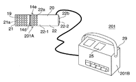
図8にコントロール部201Bをコントロールボックス29に収容した鏡面冷却式露点計201の構成を示す。コントロールボックス29において、収容されたコントロール部201Bへの電源は電池とされており、コントロールボックス29と鏡面冷却式センサ201Aを1組にして現場に赴き、鏡面冷却式センサ201Aを測定雰囲気中に設置することにより、すぐに測定を始めることができる。
FIG. 8 shows a configuration of the mirror-cooled
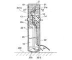
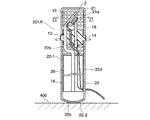
なお、鏡面冷却式センサ201Aを測定雰囲気中に設置する場合、鏡面冷却式センサ201Aの置き方に注意しなければならない。例えば、図9に示すように、鏡面冷却式センサ201Aをヒートシンクカバー22の底面22−2を下にして水平面400に置くと、熱電冷却素子2が鉛直方向上側とされ、ヒートシンク16が鉛直方向下側とされる。この鏡面冷却式センサ201Aでは、ヒートシンク16が重いため、このような置かれ方をされる場合が多い。このような置かれ方をされると、熱は下から上へ昇ろうとするので、ヒートパイプ13中を移動する熱の移動効率が悪くなる。また、ヒートシンクカバー22の底面22−2の通気孔22−2bが塞がれ、ヒートシンクカバー22内の空気の流通が悪くなる。このため、熱電冷却素子2の冷却効率が低下し、冷却性能が落ちる。
When the mirror-cooled
これに対し、本実施の形態では、ヒートシンクカバー22の底面22−2の形状が円弧状とされているので、水平面400にヒートシンクカバー22の底面22−2を接して置かれたとき、鏡面冷却式センサ201Aの重心が不安定とされる。すなわち、水平面400にヒートシンクカバー22の底面22−2を接して置くと、鏡面冷却式センサ201Aがその姿勢を保つことができず、前後方向や左右方向に転ぶ。これにより、熱電冷却素子2が鉛直方向上側に、ヒートシンク16が鉛直方向下側にして置かれるということが自然となくなり、無意識のうちにヒートパイプ13中の熱の移動効率がよくなる方向に置かれるようになる。
On the other hand, in this embodiment, since the shape of the bottom surface 22-2 of the
〔実施の形態2:鏡面冷却式露点計(ファン無し)〕
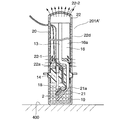
図9にはヒートシンクカバー22の内部にファン24を設けた例を示したが、図10に示すようにヒートシンクカバー22の内部にファン24を設けないタイプの鏡面冷却式センサ201A’でも同様に、ヒートシンクカバー22の底面22−2の形状を円弧状とすることによって、無意識のうちにヒートパイプ13中の熱の移動効率がよくなる方向に置かれるようにすることができる。
[Embodiment 2: Mirror surface dew point meter (no fan)]
FIG. 9 shows an example in which the
この場合、図11に示すように、鏡面冷却式センサ201A’が例えば横にして水平面400に置かれると、ヒートシンクカバー22の外周面22−1に設けられた通気孔22dを介してヒートシンクカバー22内に冷たい空気が自然に引き込まれるとともに、ヒートシンクカバー22内の暖かい空気が自然に排出され、ヒートシンク16が自然冷却されるものとなる。
In this case, as shown in FIG. 11, when the mirror-cooled
また、図12に示すように、鏡面冷却式センサ201A’が例えばヒートシンクカバー22の底面22−2を上にして水平面400に置かれると、外周面22−1の通気孔22a,22dから外の冷たい空気がヒートシンクカバー22内に引き込まれ、この空気がヒートシンク16のフィン16a間の空間を通り、底面22−2の通気孔22bから自然に排出され、ヒートシンク16が自然冷却されるものとなる。
Further, as shown in FIG. 12, when the mirror-cooled
〔実施の形態3:鏡面冷却式露点計(ファン無し、ヒートシンクカバー無し)〕
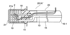
図10にはファン24を設けない例を示したが、図13に示すように、ファン24だけではなく、ヒートシンクカバー22も設けないようにしてもよい。この鏡面冷却式センサ201A”では、ヒートシンク16の底面(端面)16−1の形状を円弧状とすることによって、無意識のうちにヒートパイプ13中の熱の移動効率がよくなる方向に置かれるようにすることができる。
[Embodiment 3: Mirror surface cooling type dew point meter (no fan, no heat sink cover)]
Although FIG. 10 shows an example in which the
〔実施の形態4:冷却装置(カバーなし、ファンなし)〕
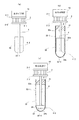
上述においては、鏡面冷却式露点計を例にとって説明したが、CPUなどの被冷却部材を冷却する冷却装置でも同様にして、放熱部材の底面を円弧状とすることによって、無意識のうちにヒートパイプ中の熱の移動効率がよくなる方向に置かれるようにすることができる。図14(a)にその一例を示す。図14(a)では、ヒートパイプ4の他端4−2に取り付けた放熱部材30の底面30−1を円弧状とし、放熱部材30の底面30−1を下にして置かれることを防いでいる。
[Embodiment 4: Cooling device (no cover, no fan)]
In the above description, a mirror-cooled dew point meter has been described as an example, but in a cooling device that cools a member to be cooled such as a CPU, the heat pipe is unconsciously formed by making the bottom surface of the heat radiating member arc-like. It can be placed in a direction that improves the efficiency of heat transfer inside. An example is shown in FIG. In FIG. 14A, the bottom surface 30-1 of the
〔実施の形態5:冷却装置(カバーあり、ファンなし)〕
また、図14(b)に示すように、ヒートパイプ4の一端4−1と他端4−2との間に保持部材31を設け、放熱部材30とこの放熱部材30から保持部材31までのヒートパイプ4を覆うカバー32を設け、このカバー32の外周面32−1に通気孔32dを形成すると共に、底面32−2を円弧状としてもよい。
[Embodiment 5: Cooling device (with cover, without fan)]
14B, the holding
〔実施の形態6:冷却装置(カバーあり、ファンあり)〕
また、図14(c)に示すように、ヒートパイプ4の一端4−1と他端4−2との間に保持部材31を設け、放熱部材30とこの放熱部材30から保持部材31までのヒートパイプ4を覆うカバー32を設け、このカバー32の外周面32−1および底面(端面)32−2に通気孔32aおよび32bを形成すると共に、底面32−2を円弧状とし、カバー32の底面32−2と放熱部材30との間の空スペース33にファン34を設けるようにしてもよい。
[Embodiment 6: Cooling device (with cover, with fan)]
14C, the holding
また、上述した実施の形態1〜6では、ヒートシンクカバー22の底面22−2やヒートシンク16の底面16−1、放熱部材30の底面30−1、カバー32の底面32−2の形状を円弧状としたが、半球状、台形状、三角錐状、円錐状などとしてもよい。
また、上述した実施の形態1〜3では、鏡面冷却式センサ201A,201A’,201A”の構成を散乱光検出方式としたが、正反射光検出方式でも本発明は適用可能である。
また、上述した実施の形態1〜3では、保持部材14を第1の保持部材14−1と第2の保持部材14−2とで構成したが、保持部材14は必ずしも分割した構成としなくてもよい。
Moreover, in Embodiment 1-6 mentioned above, the bottom face 22-2 of the
In the first to third embodiments described above, the configuration of the mirror-cooled
Moreover, in Embodiment 1-3 mentioned above, although the holding
2…熱電冷却素子(ペルチェ素子)、2−1…冷却面、2−2…加熱面、4…ヒートパイプ、4−1…一端、4−2…他端、10…被冷却部材、11…鏡、11−1…鏡面、12…温度検出素子(薄膜測温抵抗体)、13…ヒートパイプ、13−1…一端、13−2…他端、13−3…直線部、14…保持部材、14a,14b,14d…ネジ部、14c…中央部、14e…フランジ部、14−1…第1の保持部材、14−2…第2の保持部材、14−2a,14−2b…貫通孔、14−2c…ネジ部、15…ネジ、16…ヒートシンク、16a…フィン、17…リード線、18…光ファイバ、18a…先端面、18b…ネジ部、19…検知部、20…放熱部、21…ミラーカバー、21a…通気孔、21b…ネジ部、22…ヒートシンクカバー、22−1…外周面、22−2…底面、22a,22b,22d…通気孔、22c…ネジ部、23…空スペース、24…ファン、25…露点温度表示部、26…結露検知部、27…ペルチェ出力制御部、28…信号変換部、29…コントロールボックス、30…放熱部材、30−1…底面、31…保持部材、32…カバー、32a,32b,32d…通気孔、32−1…外周面、32−2…底面、33…空スペース、34…ファン、201…鏡面冷却式露点計、201A,201A’,201A”…鏡面冷却式センサ(センサ部)、201B…コントロール部。
2 ... thermoelectric cooling element (Peltier element), 2-1 ... cooling surface, 2-2 ... heating surface, 4 ... heat pipe, 4-1 ... one end, 4-2 ... other end, 10 ... member to be cooled, 11 ... Mirror, 11-1 ... Mirror surface, 12 ... Temperature detection element (thin film resistance thermometer), 13 ... Heat pipe, 13-1 ... One end, 13-2 ... Other end, 13-3 ... Linear part, 14 ... Holding
Claims (6)
前記熱電冷却素子の低温側の面に取り付けられた被冷却部材と、
前記熱電冷却素子の高温側の面にその一端が取り付けられその他端が前記熱電冷却素子から離された熱伝導体と、
前記熱伝導体の他端に取り付けられた放熱部材とを備え、
前記放熱部材の端面の形状がその端面を水平面に接して置いたときに重心を不安定とする形状とされている
ことを特徴とする冷却装置。 A thermoelectric cooling element in which one surface is a low temperature side and the other surface is a high temperature side;
A member to be cooled attached to a low-temperature surface of the thermoelectric cooling element;
A heat conductor having one end attached to the surface of the thermoelectric cooling element on the high temperature side and the other end separated from the thermoelectric cooling element;
A heat dissipating member attached to the other end of the heat conductor,
The cooling device according to claim 1, wherein the shape of the end face of the heat dissipating member is such that the center of gravity becomes unstable when the end face is placed in contact with a horizontal plane.
前記熱電冷却素子の低温側の面に取り付けられた被冷却部材と、
前記熱電冷却素子の高温側の面にその一端が取り付けられその他端が前記熱電冷却素子から離された熱伝導体と、
前記熱伝導体の一端と他端との間に設けられた保持部材と、
前記熱伝導体の他端に取り付けられた放熱部材と、
前記放熱部材とこの放熱部材から前記保持部材までの前記熱伝導体を覆うカバーとを備え、
前記カバーの端面の形状がその端面を水平面に接して置いたときに重心を不安定とする形状とされ、
前記カバーの前記放熱部材と対向する周壁に通気孔が形成されている
ことを特徴とする冷却装置。 A thermoelectric cooling element in which one surface is a low temperature side and the other surface is a high temperature side;
A member to be cooled attached to a low-temperature surface of the thermoelectric cooling element;
A heat conductor having one end attached to the surface of the thermoelectric cooling element on the high temperature side and the other end separated from the thermoelectric cooling element;
A holding member provided between one end and the other end of the heat conductor;
A heat dissipating member attached to the other end of the heat conductor;
The heat dissipation member and a cover that covers the heat conductor from the heat dissipation member to the holding member,
The shape of the end surface of the cover is a shape that makes the center of gravity unstable when the end surface is placed in contact with a horizontal plane,
A cooling device, wherein a vent hole is formed in a peripheral wall of the cover facing the heat radiating member.
前記熱電冷却素子の低温側の面に取り付けられた被冷却部材と、
前記熱電冷却素子の高温側の面にその一端が取り付けられその他端が前記熱電冷却素子から離された熱伝導体と、
前記熱伝導体の一端と他端との間に設けられた保持部材と、
前記熱伝導体の他端に取り付けられた放熱部材と、
前記放熱部材とこの放熱部材から前記保持部材までの前記熱伝導体を覆うカバーとを備え、
前記カバーの端面の形状がその端面を水平面に接して置いたときに重心を不安定とする形状とされ、
前記カバーの端面および前記保持部材と前記放熱部材との間の周壁に通気孔が形成され、
前記カバー内にファンが設けられている
ことを特徴とする冷却装置。 A thermoelectric cooling element in which one surface is a low temperature side and the other surface is a high temperature side;
A member to be cooled attached to a low-temperature surface of the thermoelectric cooling element;
A heat conductor having one end attached to the surface of the thermoelectric cooling element on the high temperature side and the other end separated from the thermoelectric cooling element;
A holding member provided between one end and the other end of the heat conductor;
A heat dissipating member attached to the other end of the heat conductor;
The heat dissipation member and a cover that covers the heat conductor from the heat dissipation member to the holding member,
The shape of the end surface of the cover is a shape that makes the center of gravity unstable when the end surface is placed in contact with a horizontal plane,
A vent hole is formed in the end surface of the cover and the peripheral wall between the holding member and the heat dissipation member,
A cooling device, wherein a fan is provided in the cover.
前記鏡の鏡面とは反対側の面に低温側の面が取り付けられた熱電冷却素子と、
前記鏡の鏡面に対して光を照射する発光手段と、
前記発光手段から前記鏡面に対して照射された光の反射光を受光する受光手段と、
前記熱電冷却素子の高温側の面にその一端が取り付けられその他端が前記熱電冷却素子から離された熱伝導体と、
前記熱伝導体の他端に取り付けられた放熱部材とを備え、
前記放熱部材の端面の形状がその端面を水平面に接して置いたときに重心を不安定とする形状とされている
ことを特徴とする鏡面冷却式センサ。 A mirror whose mirror surface is exposed to the gas to be measured;
A thermoelectric cooling element in which a low-temperature side surface is attached to a surface opposite to the mirror surface of the mirror;
A light emitting means for irradiating the mirror surface of the mirror with light;
A light receiving means for receiving reflected light of the light emitted from the light emitting means to the mirror surface;
A heat conductor having one end attached to the surface of the thermoelectric cooling element on the high temperature side and the other end separated from the thermoelectric cooling element;
A heat dissipating member attached to the other end of the heat conductor,
The shape of the end surface of the heat radiating member is a shape that makes the center of gravity unstable when the end surface is placed in contact with a horizontal plane.
前記鏡の鏡面とは反対側の面に低温側の面が取り付けられた熱電冷却素子と、
前記鏡の鏡面に対して光を照射する発光手段と、
前記発光手段から前記鏡面に対して照射された光の反射光を受光する受光手段と、
前記熱電冷却素子の高温側の面にその一端が取り付けられその他端が前記熱電冷却素子から離された熱伝導体と、
前記熱伝導体の一端と他端との間に設けられた保持部材と、
前記熱伝導体の他端に取り付けられた放熱部材と、
前記放熱部材とこの放熱部材から前記保持部材までの前記熱伝導体を覆うカバーとを備え、
前記カバーの端面の形状がその端面を水平面に接して置いたときに重心を不安定とする形状とされ、
前記カバーの前記放熱部材と対向する周壁に通気孔が形成されている
ことを特徴とする鏡面冷却式センサ。 A mirror whose mirror surface is exposed to the gas to be measured;
A thermoelectric cooling element in which a low-temperature side surface is attached to a surface opposite to the mirror surface of the mirror;
A light emitting means for irradiating the mirror surface of the mirror with light;
A light receiving means for receiving reflected light of the light emitted from the light emitting means to the mirror surface;
A heat conductor having one end attached to the surface of the thermoelectric cooling element on the high temperature side and the other end separated from the thermoelectric cooling element;
A holding member provided between one end and the other end of the heat conductor;
A heat dissipating member attached to the other end of the heat conductor;
The heat dissipation member and a cover that covers the heat conductor from the heat dissipation member to the holding member,
The shape of the end surface of the cover is a shape that makes the center of gravity unstable when the end surface is placed in contact with a horizontal plane,
The mirror surface cooling type sensor characterized by the vent hole being formed in the surrounding wall facing the said heat radiating member of the said cover.
前記鏡の鏡面とは反対側の面に低温側の面が取り付けられた熱電冷却素子と、
前記鏡の鏡面に対して光を照射する発光手段と、
前記発光手段から前記鏡面に対して照射された光の反射光を受光する受光手段と、
前記熱電冷却素子の高温側の面にその一端が取り付けられその他端が前記熱電冷却素子から離された熱伝導体と、
前記熱伝導体の一端と他端との間に設けられた保持部材と、
前記熱伝導体の他端に取り付けられた放熱部材と、
前記放熱部材とこの放熱部材から前記保持部材までの前記熱伝導体を覆うカバーとを備え、
前記カバーの端面の形状がその端面を水平面に接して置いたときに重心を不安定とする形状とされ、
前記カバーの端面および前記保持部材と前記放熱部材との間の周壁に通気孔が形成され、
前記カバー内にファンが設けられている
ことを特徴とする鏡面冷却式センサ。
A mirror whose mirror surface is exposed to the gas to be measured;
A thermoelectric cooling element in which a low-temperature side surface is attached to a surface opposite to the mirror surface of the mirror;
A light emitting means for irradiating the mirror surface of the mirror with light;
A light receiving means for receiving reflected light of the light emitted from the light emitting means to the mirror surface;
A heat conductor having one end attached to the surface of the thermoelectric cooling element on the high temperature side and the other end separated from the thermoelectric cooling element;
A holding member provided between one end and the other end of the heat conductor;
A heat dissipating member attached to the other end of the heat conductor;
The heat dissipation member and a cover that covers the heat conductor from the heat dissipation member to the holding member,
The shape of the end surface of the cover is a shape that makes the center of gravity unstable when the end surface is placed in contact with a horizontal plane,
A vent hole is formed in the end surface of the cover and a peripheral wall between the holding member and the heat dissipation member,
A mirror cooled sensor, wherein a fan is provided in the cover.
Priority Applications (1)
| Application Number | Priority Date | Filing Date | Title |
|---|---|---|---|
| JP2004106730A JP3999758B2 (en) | 2004-03-31 | 2004-03-31 | Cooling device and mirror cooled sensor |
Applications Claiming Priority (1)
| Application Number | Priority Date | Filing Date | Title |
|---|---|---|---|
| JP2004106730A JP3999758B2 (en) | 2004-03-31 | 2004-03-31 | Cooling device and mirror cooled sensor |
Publications (2)
| Publication Number | Publication Date |
|---|---|
| JP2005291893A true JP2005291893A (en) | 2005-10-20 |
| JP3999758B2 JP3999758B2 (en) | 2007-10-31 |
Family
ID=35324984
Family Applications (1)
| Application Number | Title | Priority Date | Filing Date |
|---|---|---|---|
| JP2004106730A Expired - Fee Related JP3999758B2 (en) | 2004-03-31 | 2004-03-31 | Cooling device and mirror cooled sensor |
Country Status (1)
| Country | Link |
|---|---|
| JP (1) | JP3999758B2 (en) |
Cited By (3)
| Publication number | Priority date | Publication date | Assignee | Title |
|---|---|---|---|---|
| CN111254432A (en) * | 2020-03-27 | 2020-06-09 | 江苏珠峰光电科技有限公司 | Full water-cooling high-power inner hole broadband cladding head |
| CN112525847A (en) * | 2020-12-03 | 2021-03-19 | 中国科学院上海技术物理研究所 | Wide-temperature-zone condensable volatile real-time spectrum testing device and testing method |
| CN115971791A (en) * | 2022-09-16 | 2023-04-18 | 国家石油天然气管网集团有限公司 | Chilled mirror manufacturing method, chilled mirror device and dew point meter based on Stirling refrigerator |
-
2004
- 2004-03-31 JP JP2004106730A patent/JP3999758B2/en not_active Expired - Fee Related
Cited By (5)
| Publication number | Priority date | Publication date | Assignee | Title |
|---|---|---|---|---|
| CN111254432A (en) * | 2020-03-27 | 2020-06-09 | 江苏珠峰光电科技有限公司 | Full water-cooling high-power inner hole broadband cladding head |
| CN111254432B (en) * | 2020-03-27 | 2024-05-17 | 江苏珠峰光电科技有限公司 | A fully water-cooled high-power inner hole wide-band cladding head |
| CN112525847A (en) * | 2020-12-03 | 2021-03-19 | 中国科学院上海技术物理研究所 | Wide-temperature-zone condensable volatile real-time spectrum testing device and testing method |
| CN112525847B (en) * | 2020-12-03 | 2022-12-30 | 中国科学院上海技术物理研究所 | Wide-temperature-zone condensable volatile real-time spectrum testing device and testing method |
| CN115971791A (en) * | 2022-09-16 | 2023-04-18 | 国家石油天然气管网集团有限公司 | Chilled mirror manufacturing method, chilled mirror device and dew point meter based on Stirling refrigerator |
Also Published As
| Publication number | Publication date |
|---|---|
| JP3999758B2 (en) | 2007-10-31 |
Similar Documents
| Publication | Publication Date | Title |
|---|---|---|
| US7736051B2 (en) | Thermoelectric device and mirror surface state detection device | |
| TWI421491B (en) | Hygrometer, dew point meter and constant temperature and humidity tank | |
| RU2506502C2 (en) | Device for measurement and control of volumetric flux in ventilation pipe | |
| JP5541576B2 (en) | Wind direction anemometer and wind direction wind speed device | |
| JP6718023B2 (en) | Gas sensor and thermostat | |
| JP4025308B2 (en) | Mirror surface cooling type sensor | |
| JP3999758B2 (en) | Cooling device and mirror cooled sensor | |
| JP3866730B2 (en) | Moisture detector | |
| JP2007024727A (en) | Window thermal performance measuring device | |
| JP4054002B2 (en) | Mirror surface cooling type sensor | |
| US11231399B2 (en) | Sample temperature adjustment device | |
| US7168850B2 (en) | Mirror surface state detection device and moisture detection device | |
| JP4237692B2 (en) | Mirror surface cooling type sensor | |
| JP4575213B2 (en) | Mirror surface cooling type sensor | |
| JP4139377B2 (en) | Mirror surface cooling type sensor | |
| CN210005703U (en) | A thermostat for temperature sensitive devices | |
| JP4197508B2 (en) | Mirror surface cooling type sensor | |
| JP4139376B2 (en) | Mirror surface cooling type sensor | |
| JP4012166B2 (en) | Mirror surface dew point meter | |
| JP4571537B2 (en) | Mirror surface cooling type sensor | |
| JP4541956B2 (en) | Mirror surface cooling type sensor | |
| JP4005580B2 (en) | Mirror surface dew point meter | |
| JP2012047581A (en) | Wet-bulb thermometer | |
| WO2013008753A1 (en) | Humidity sensor | |
| JPH0528946A (en) | Beam tester temperature controller |
Legal Events
| Date | Code | Title | Description |
|---|---|---|---|
| A621 | Written request for application examination |
Free format text: JAPANESE INTERMEDIATE CODE: A621 Effective date: 20051226 |
|
| A977 | Report on retrieval |
Free format text: JAPANESE INTERMEDIATE CODE: A971007 Effective date: 20070705 |
|
| TRDD | Decision of grant or rejection written | ||
| A01 | Written decision to grant a patent or to grant a registration (utility model) |
Free format text: JAPANESE INTERMEDIATE CODE: A01 Effective date: 20070807 |
|
| A61 | First payment of annual fees (during grant procedure) |
Free format text: JAPANESE INTERMEDIATE CODE: A61 Effective date: 20070809 |
|
| R150 | Certificate of patent or registration of utility model |
Ref document number: 3999758 Country of ref document: JP Free format text: JAPANESE INTERMEDIATE CODE: R150 Free format text: JAPANESE INTERMEDIATE CODE: R150 |
|
| FPAY | Renewal fee payment (event date is renewal date of database) |
Free format text: PAYMENT UNTIL: 20100817 Year of fee payment: 3 |
|
| FPAY | Renewal fee payment (event date is renewal date of database) |
Free format text: PAYMENT UNTIL: 20100817 Year of fee payment: 3 |
|
| FPAY | Renewal fee payment (event date is renewal date of database) |
Free format text: PAYMENT UNTIL: 20110817 Year of fee payment: 4 |
|
| FPAY | Renewal fee payment (event date is renewal date of database) |
Free format text: PAYMENT UNTIL: 20120817 Year of fee payment: 5 |
|
| FPAY | Renewal fee payment (event date is renewal date of database) |
Free format text: PAYMENT UNTIL: 20130817 Year of fee payment: 6 |
|
| FPAY | Renewal fee payment (event date is renewal date of database) |
Free format text: PAYMENT UNTIL: 20130817 Year of fee payment: 6 |
|
| FPAY | Renewal fee payment (event date is renewal date of database) |
Free format text: PAYMENT UNTIL: 20140817 Year of fee payment: 7 |
|
| LAPS | Cancellation because of no payment of annual fees |