JP2005291652A - Air conditioning method and air conditioner - Google Patents
Air conditioning method and air conditioner Download PDFInfo
- Publication number
- JP2005291652A JP2005291652A JP2004109660A JP2004109660A JP2005291652A JP 2005291652 A JP2005291652 A JP 2005291652A JP 2004109660 A JP2004109660 A JP 2004109660A JP 2004109660 A JP2004109660 A JP 2004109660A JP 2005291652 A JP2005291652 A JP 2005291652A
- Authority
- JP
- Japan
- Prior art keywords
- heat
- heat medium
- heat exchange
- exchange coil
- temperature
- Prior art date
- Legal status (The legal status is an assumption and is not a legal conclusion. Google has not performed a legal analysis and makes no representation as to the accuracy of the status listed.)
- Granted
Links
Images

Landscapes
- Air Conditioning Control Device (AREA)
Abstract
【課題】シングル・ブリード・イン方式を採用しつつも、ダブル・ブリード・イン方式とほぼ同等、若しくはそれ以上に室内温度の変動を極めて小さく制御可能とする。
【解決手段】室内温度計15及び/又は給気温度計17による計測温度に温度変化が生じたならば、前記温度変化を解消し元の設定温度に修正し得る前記熱交換コイル2における熱交換量と、熱源から前記熱媒循環系統Rに供給される熱量とが等しくなるように、熱源3から前記熱媒循環系統Rに供給すべき熱媒供給量Qwiを算出するとともに、この算出された熱媒供給量Qwiを熱交換コイル入口での熱媒温度の変化による熱量バランスへの影響ズレを無くすようにタイミング調整を行った熱媒供給量Q'wiに修正し、この修正熱媒供給量Q'wiを前記熱媒循環系統に供給するように流量制御する。
【選択図】図1
While adopting a single bleed-in method, it is possible to control the fluctuation of the room temperature to be substantially the same as or more than the double bleed-in method.
If a temperature change occurs in a temperature measured by an indoor thermometer and / or a supply air thermometer, heat exchange in the heat exchange coil can be corrected to the original set temperature. The heat medium supply amount Qwi to be supplied from the heat source 3 to the heat medium circulation system R is calculated so that the amount and the heat amount supplied from the heat source to the heat medium circulation system R are equal to each other. The heat medium supply amount Qwi is corrected to the heat medium supply amount Q'wi that has been adjusted so as to eliminate the effect on the heat balance due to the change of the heat medium temperature at the entrance of the heat exchange coil, and this corrected heat medium supply amount The flow rate is controlled so that Q′wi is supplied to the heat medium circulation system.
[Selection] Figure 1
Description
本発明は、クリーンルーム等の恒温室において、室内温度の変動を極めて小さく制御可能な空調方法及び空調装置に関する。 The present invention relates to an air-conditioning method and an air-conditioning apparatus that can control fluctuations in room temperature in a constant temperature room such as a clean room.
近年の産業は省力化、高機能化により電子機器の利用が不可欠となっており、これらの基盤技術の研究、開発が多くの企業で活発に行われている。これらの開発や製造を行うためには精密に温度制御された環境が必要とされており、この要求を満たすべく温度変動範囲が0.01℃以下の超精密温調室や、大規模精密温調室が多々紹介されている。 In recent years, the use of electronic devices has become indispensable due to labor saving and high functionality in industries, and research and development of these basic technologies are being actively conducted by many companies. In order to perform these developments and productions, a precisely temperature-controlled environment is required. To meet this requirement, an ultra-precise temperature control room with a temperature fluctuation range of 0.01 ° C or less, a large-scale precision temperature control room, etc. A lot of preparation rooms are introduced.
温度変動範囲を上記範囲内のように極力最小に抑えるための空調装置としては、主に3通りの方式が知られており、再熱システム方式は、電気ヒーターを用いて一度冷却した熱媒を再度温めて要求精度を維持する方式である。しかし、前記再熱システム方式では、一度冷却した熱媒を再度温めるためエネルギー損失が大きいなどの問題がある。この問題を解決するために提案されたのがブリード・イン方式である。このブリード・イン方式には、熱媒循環系統を単一とするシングル・ブリード・イン方式と、熱媒循環系統を二重に形成するダブル・ブリード・イン方式とがある。 There are mainly three types of air conditioners that are used to minimize the temperature fluctuation range within the above range. The reheating system method uses a heating medium that has been cooled once using an electric heater. This is a method of reheating and maintaining the required accuracy. However, the reheat system method has a problem that energy loss is large because the heat medium once cooled is reheated. The bleed-in method has been proposed to solve this problem. This bleed-in method includes a single bleed-in method in which a single heat medium circulation system is used, and a double bleed-in method in which two heat medium circulation systems are formed.
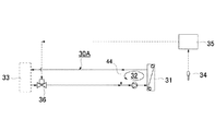
前者のシングル・ブリード・イン方式は、図9に示される空調装置30Aのように、熱交換コイル31への送給路と、熱交換コイル31からの還流路とを繋ぐバイパス44によって熱交換コイル31との間にブリード・インと呼ばれる熱媒循環系統32を設け、前記熱交換コイル31より還流される熱媒の一部を、熱源33より供給される熱媒に混合させて熱交換コイル31に再供給するようにしたもので、熱源からの熱媒供給量は、室内温度計34と接続された室内温度制御機器35により制御弁36を開度制御することにより調整されるようになっている。この方式では、熱媒循環系統32に循環させる熱媒量を通常の3〜4倍とすることで、熱源から供給される熱媒変動による影響を極小化し要求精度を維持できる利点がある。
The former single bleed-in method uses a
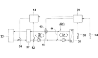
後者のダブル・ブリード・イン方式は、下記特許文献1に開示される方式で、前記シングル・ブリード・イン方式をさらに発展させたものである。具体的には図10に示される空調装置30Bのように、熱交換コイル31と熱源33との間に第2の熱交換コイル37を設け、前記熱交換コイル31部では上記シングル・ブリード・イン方式と同様に熱媒循環系統32を形成し、かつ第2のバイパス45を形成することにより前記第2熱交換コイル37を巡る第2熱媒循環系統41を形成し、室内温度計34と給気温度計38とに基づいて第1コントローラ39により制御弁40を開閉制御することにより、前記熱媒循環系統32への熱媒供給量を制御するとともに、前記第2熱媒循環系統41に設けられた送水温度計42に基づいて第2コントローラ43により制御弁36を開閉制御することにより熱媒供給量を制御する方式である。このダブル・ブリード・イン方式では、第2熱媒循環系統41を設けたことにより、前記シングル・ブリード・イン方式よりもさらに、熱源から供給される熱媒変動による影響を極小化できるようになり、高い精度で要求精度が維持できるようになる。
しかしながら、上記シングル・ブリード・イン方式では、循環させる熱媒量を増やすことである程度、要求精度の向上を図ることは可能であるけれども、その量にも物理的な限界がある。また、熱媒量を増やせば設備費と運転費の増大を招くようになる。 However, in the single bleed-in method, it is possible to improve the required accuracy to some extent by increasing the amount of circulating heat medium, but the amount is physically limited. Moreover, if the amount of the heat medium is increased, the equipment cost and the operating cost are increased.
一方で、前記ダブル・ブリート・イン方式の場合には、高い精度で室内温度を一定に制御することが可能になるけれども、熱媒回路が複雑になるとともに、システムの構成機器が増えるため、設備費が増大するとともに、工期も延びることになる。 On the other hand, in the case of the double breath-in method, the room temperature can be controlled to a constant level with high accuracy, but the heat medium circuit becomes complicated and the number of system components increases. The cost will increase and the construction period will be extended.
そこで、本発明の主たる課題は、シングル・ブリード・イン方式を採用しつつも、ダブル・ブリード・イン方式とほぼ同等、若しくはそれ以上に室内温度の変動を極めて小さく制御可能とする空調方法および装置を提供することにある。 Accordingly, the main problem of the present invention is that it adopts the single bleed-in method, and is capable of controlling the fluctuation of the indoor temperature to be almost the same as or more than the double bleed-in method, and an air conditioning method and apparatus capable of controlling it. Is to provide.
前記課題を解決するために請求項1に係る本発明として、熱交換コイルへの送給路と、熱交換コイルからの還流路とを繋ぐバイパスによって前記熱交換コイルを巡る熱媒循環系統を形成し、前記熱交換コイルから還流される熱媒の一部を、熱源から供給される熱媒に混合させて前記熱交換コイルに再供給するようにした空調方法において、
室内温度計及び/又は給気温度計による計測温度に温度変化が生じたならば、前記温度変化を解消し元の設定温度に修正し得る前記熱交換コイルにおける熱交換量と、熱源から前記熱媒循環系統に供給される熱量とが等しくなるように、熱源から前記熱媒循環系統に供給すべき熱媒供給量を算出するとともに、この算出された熱媒供給量を、熱源からの熱媒温度変化の影響ズレを無くすようにタイミング調整を行った熱媒供給量に修正し、この修正熱媒供給量を前記熱媒循環系統に供給するように流量制御することを特徴とする空調方法が提供される。
In order to solve the above-mentioned problem, as the present invention according to
If a temperature change occurs in the temperature measured by the indoor thermometer and / or the supply air thermometer, the heat exchange amount in the heat exchange coil that can be corrected to the original set temperature by eliminating the temperature change, and the heat from the heat source. A heat medium supply amount to be supplied from the heat source to the heat medium circulation system is calculated so that the heat amount supplied to the medium circulation system is equal, and the calculated heat medium supply amount is calculated using the heat medium supply amount from the heat source. An air conditioning method characterized by correcting to a heating medium supply amount that has been subjected to timing adjustment so as to eliminate the influence of temperature change, and controlling the flow rate so as to supply the corrected heating medium supply amount to the heating medium circulation system Provided.
上記請求項1記載の本発明においては、室内温度計及び/又は給気温度計による計測温度に温度変化が生じたならば、前記温度変化を解消し元の設定温度に修正し得る前記熱交換コイルにおける熱交換量と、熱源から前記熱媒循環系統に供給される熱量とが等しくなるように、熱源から前記熱媒循環系統に供給すべき熱媒供給量を算出し、この算出された熱媒供給量を、熱源からの熱媒温度変化の影響ズレを無くすようにタイミング調整を行った熱媒供給量に修正するようにしている。
In the present invention as set forth in
シングル・ブリード・イン方式における制御誤差の主たる原因は、熱源より供給される熱媒の温度変化の影響が送風温度又は熱交換コイル入口での熱媒温度変化に現れるタイミングと、熱媒供給量の変化の影響が送風温度又は熱交換コイル入口での熱媒温度変化に現れるタイミングとが異なるためであるとの知見から、本発明では、熱源からの熱媒温度変化の影響ズレを無くすようにタイミング調整を行った熱媒供給量に修正することにより、両者のタイミングズレを無くし、過渡状態での制御の安定性を維持するようにした。 The main causes of control errors in the single bleed-in method are the timing at which the influence of the temperature change of the heat medium supplied from the heat source appears in the air temperature or the heat medium temperature change at the heat exchange coil inlet, and the amount of heat medium supply In view of the fact that the influence of the change differs from the timing at which the air temperature changes or the timing at which the heat medium temperature changes at the inlet of the heat exchange coil appears, in the present invention, the timing is set so as to eliminate the effect of the heat medium temperature change from the heat source. By correcting to the adjusted heating medium supply amount, the timing deviation between the two is eliminated, and the stability of the control in the transient state is maintained.
その結果、後述の実施例で検証されるように、シングル・ブリード・イン方式を採用しつつも、ダブル・ブリード・イン方式とほぼ同等、若しくはそれ以上に室内温度の変動を極めて小さく制御可能となる。 As a result, as will be verified in the examples described later, while adopting the single bleed-in method, it is possible to control the fluctuation of the room temperature to be almost the same as or more than the double bleed-in method. Become.
請求項2に係る本発明として、熱交換コイルへの送給路と、熱交換コイルからの還流路とを繋ぐバイパスによって前記熱交換コイルを巡る熱媒循環系統を形成し、前記熱交換コイルから還流される熱媒の一部を、熱源から供給される熱媒に混合させて前記熱交換コイルに再供給するようにした空調方法において、
室内温度計及び/又は給気温度計による計測温度に温度変化が生じたならば、前記温度変化を解消し元の設定温度に修正するための前記熱交換コイルにおける熱交換量を求め、
前記熱交換コイルにおける熱交換量と、熱源から前記熱媒循環系統に供給される熱量とが等しくなる条件の熱量バランス方程式に基づいて、前記熱媒循環系統入側での熱媒温度、前記熱媒循環系統出側での熱媒温度および前記熱交換コイルにおける熱交換量とから、熱源から前記熱媒循環系統に供給すべき熱媒供給量を算出するとともに、この算出された熱媒供給量を、熱源からの熱媒温度変化の影響ズレを無くすようにタイミング調整を行った熱媒供給量に修正し、この修正熱媒供給量を前記熱媒循環系統に供給するように流量制御することを特徴とする空調方法が提供される。
As the present invention according to
If a temperature change occurs in the temperature measured by the indoor thermometer and / or the supply air thermometer, the amount of heat exchange in the heat exchange coil for eliminating the temperature change and correcting to the original set temperature is obtained,
Based on the heat quantity balance equation under the condition that the heat exchange amount in the heat exchange coil and the heat quantity supplied from the heat source to the heat medium circulation system are equal, the heat medium temperature on the inlet side of the heat medium circulation system, the heat The heat medium supply amount to be supplied from the heat source to the heat medium circulation system is calculated from the heat medium temperature on the outlet side of the medium circulation system and the heat exchange amount in the heat exchange coil, and the calculated heat medium supply amount Is adjusted to a heat medium supply amount that is adjusted in timing so as to eliminate the influence of the change in temperature of the heat medium from the heat source, and the flow rate is controlled so that this corrected heat medium supply amount is supplied to the heat medium circulation system. An air conditioning method is provided.
請求項3に係る本発明として、熱交換コイルへの送給路と、熱交換コイルからの還流路とを繋ぐバイパスによって前記熱交換コイルを巡る熱媒循環系統を形成し、前記熱交換コイルから還流される熱媒の一部を、熱源から供給される熱媒に混合させて前記熱交換コイルに再供給するようにした空調方法において、
室内温度計及び/又は給気温度計による計測温度に温度変化が生じたならば、前記温度変化を解消し元の設定温度に修正するための前記熱交換コイル入口での熱媒温度を求め、
前記熱交換コイルにおける熱交換量と、熱源から前記熱媒循環系統に供給される熱量とが等しくなる条件の熱量バランス方程式に基づいて、前記熱媒循環系統入側での熱媒温度、前記熱媒循環系統出側での熱媒温度、前記熱媒循環系統における循環熱媒量および前記熱交換コイル入口での熱媒温度とから、熱源から前記熱媒循環系統に供給すべき熱媒供給量を算出するとともに、この算出された熱媒供給量を、熱源からの熱媒温度変化の影響ズレを無くすようにタイミング調整を行った熱媒供給量に修正し、この修正熱媒供給量を前記熱媒循環系統に供給するように流量制御することを特徴とする空調方法が提供される。
As the present invention according to
If a temperature change occurs in the temperature measured by the indoor thermometer and / or the supply air thermometer, obtain the heat medium temperature at the inlet of the heat exchange coil for eliminating the temperature change and correcting it to the original set temperature,
Based on the heat quantity balance equation under the condition that the heat exchange amount in the heat exchange coil and the heat quantity supplied from the heat source to the heat medium circulation system are equal, the heat medium temperature on the inlet side of the heat medium circulation system, the heat Heat medium supply amount to be supplied from the heat source to the heat medium circulation system from the heat medium temperature at the outlet side of the medium circulation system, the amount of the circulation heat medium in the heat medium circulation system and the heat medium temperature at the inlet of the heat exchange coil And the calculated heating medium supply amount is corrected to a heating medium supply amount that is adjusted in timing so as to eliminate the influence of the change in temperature of the heating medium from the heat source. There is provided an air conditioning method characterized by controlling a flow rate so as to be supplied to a heat medium circulation system.
請求項4に係る本発明として、前記タイミング調整を行った熱媒供給量への修正は、ラプラス変換による進み遅れ要素とむだ時間要素とを組み合わせた下記(1)の伝達関数によって行う請求項1〜3いずれかに記載の空調方法。 According to a fourth aspect of the present invention, the correction to the heating medium supply amount that has been subjected to the timing adjustment is performed by a transfer function of the following (1) that combines an advance / delay element by a Laplace transform and a dead time element. The air conditioning method according to any one of? 3.
Y(s)=e-Ls*(1+T1s)/(1+T2s)*X(s) ……(1)
ここに、Y:出力、X:入力、L:むだ時間、T1:進み時定数、T2:遅れ時定数とする。
Y (s) = e -Ls * (1 + T1s) / (1 + T2s) * X (s) ...... (1)
Here, Y: output, X: input, L: dead time, T1: lead time constant, T2: delay time constant.
請求項5に係る本発明として、熱交換コイルへの送給路と、熱交換コイルからの還流路とを繋ぐバイパスによって前記熱交換コイルを巡る熱媒循環系統を形成し、前記熱交換コイルから還流される熱媒の一部を、熱源から供給される熱媒に混合させて前記熱交換コイルに再供給するようにした空調装置において、
前記熱媒循環系統入側に設置された熱媒温度計、熱媒循環系統出側に設置された熱媒温度計、室内に設置された室内温度計及び/又は吹出口部に設置された給気温度計からなる温度計測機器群と、
この室内温度計及び/又は給気温度計による計測温度に温度変化が生じたならば、前記温度変化を解消し元の設定温度に修正するための前記熱交換コイルにおける熱交換量又は前記熱交換コイル入口での熱媒温度を求めるための熱量演算機器と、
前記熱交換コイルにおける熱交換量と、熱源から前記熱媒循環系統に供給される熱量とが等しくなる条件の熱量バランス方程式に基づいて、前記熱媒循環系統入側での熱媒温度、前記熱媒循環系統出側での熱媒温度および前記熱交換コイルにおける熱交換量又は前記熱媒循環系統における循環熱媒量および前記熱交換コイル入口での熱媒温度とから、熱源から前記熱媒循環系統に供給すべき熱媒供給量を算出する熱量バランス演算機器と、
この算出された熱媒供給量を、熱源からの熱媒温度変化の影響ズレを無くすようにタイミング調整を行った熱媒供給量に修正するためのタイミング調整機器と、
この修正熱媒供給量を前記熱媒循環系統に供給するために前記熱媒の供給路に設けた制御弁を開度調整するための流量制御機器とからなることを特徴とする空調装置が提供される。
As this invention which concerns on
Heat medium thermometer installed on the inlet side of the heat medium circulation system, heat medium thermometer installed on the outlet side of the heat medium circulation system, indoor thermometer installed indoors and / or a supply installed in the outlet A temperature measuring device group consisting of a thermometer,
If a temperature change occurs in the temperature measured by the indoor thermometer and / or the supply air thermometer, the heat exchange amount in the heat exchange coil or the heat exchange for canceling the temperature change and correcting to the original set temperature A calorific value calculation device for obtaining the heat medium temperature at the coil inlet;
Based on the heat quantity balance equation under the condition that the heat exchange amount in the heat exchange coil and the heat quantity supplied from the heat source to the heat medium circulation system are equal, the heat medium temperature on the inlet side of the heat medium circulation system, the heat The heat medium circulation from the heat source from the heat medium temperature on the outlet side of the medium circulation system and the heat exchange amount in the heat exchange coil or the amount of the circulation heat medium in the heat medium circulation system and the heat medium temperature at the inlet of the heat exchange coil A heat balance calculator that calculates the amount of heat medium to be supplied to the system;
A timing adjustment device for correcting the calculated heat medium supply amount to a heat medium supply amount that has been subjected to timing adjustment so as to eliminate the influence of the heat medium temperature change from the heat source;
An air conditioner comprising: a flow rate control device for adjusting the opening of a control valve provided in the supply path of the heating medium to supply the corrected heating medium supply amount to the heating medium circulation system is provided. Is done.
以上詳説のとおり本発明によれば、シングル・ブリード・イン方式を採用しつつも、ダブル・ブリード・イン方式とほぼ同等、若しくはそれ以上に室内温度の変動を極めて小さく制御可能とすることができる。さらに個別的に効果を列挙すれば、
(1)再熱システムのように、電気ヒータによる再熱動作を必要としないため運転費が低減できる。
(2)シングル・ブリード・イン方式ではあるが、循環熱媒量を増やさずに室内温度精度を飛躍的に高められ、かつ設備費や運転費の増大を招かない。
(3)既設のシングル・ブリード・イン方式に対して、制御機器の追加と、熱媒循環系統の出入口部への温度計および流量計の追加のみで、本発明空調装置への変更が可能である。また、設備改修期間の短縮が可能であるとともに、改修費が安価で済むようになる。
As described above in detail, according to the present invention, it is possible to control the fluctuation of the indoor temperature to be extremely small or substantially the same as or more than the double bleed-in method while adopting the single bleed-in method. . If you list the effects individually,
(1) Unlike the reheating system, the operation cost can be reduced because the reheating operation by the electric heater is not required.
(2) Although it is a single bleed-in method, the indoor temperature accuracy can be dramatically increased without increasing the amount of circulating heat medium, and the equipment and operating costs will not increase.
(3) The existing single bleed-in system can be changed to the air conditioner of the present invention simply by adding a control device and adding a thermometer and a flow meter to the inlet / outlet part of the heat medium circulation system. is there. In addition, the facility repair period can be shortened and the repair cost can be reduced.
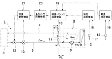
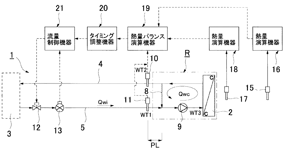
以下、本発明の実施の形態について図面を参照しながら詳述する。図1は本発明に係る空調装置1の概略構成図である。
Hereinafter, embodiments of the present invention will be described in detail with reference to the drawings. FIG. 1 is a schematic configuration diagram of an
本空調装置1は、クリーンルーム等の極めて狭い温度変動範囲内にあることが要求される精密温調室等に設けられるものであり、負荷側に設けられて冷水または温水(以下、熱媒という。)を室内への給気と熱交換する熱交換コイル2と、この熱交換コイル2の反対側に設けられた熱媒を製造する熱源3との間に、熱交換コイル2より還流された熱媒の流路となるレタン管4と、熱源3より供給される熱媒の流路となるサプライ管5が設けられ、かつ双方の管路4,5間を繋ぐバイパス管8が設けられ、前記熱交換コイル2へのサプライ管5と、熱交換コイル2からのレタン管4とを繋ぐバイパス管8によって前記熱交換コイル2を巡る熱媒循環系統Rを形成し、前記熱交換コイル2から還流される熱媒の一部を、熱源から供給される熱媒に混合させて前記熱交換コイル2に再供給するようにしたシングル・ブリード・イン方式の空調方式である。なお、符号9は前記熱媒循環系統R経路中に設けられたポンプである。
The
本発明では、前記熱媒循環系統Rの入側での熱媒温度WT1を測定するために前記バイパス路8の上流側位置に熱媒温度計11を配設するとともに、前記熱媒循環系統Rの出側での熱媒温度WT2を測定するために前記バイパス管8の下流側位置に熱媒温度計10を配設し、かつ室内への吹出口部近傍には送風温度を計測するための給気温度計17、室内温度を計測するための室内温度計15からなる温度計測機器群が夫々配設されている。なお、前記給気温度計17及び室内温度計15の一方だけを設置するようにしてもよい。
In the present invention, in order to measure the heat medium temperature WT1 on the inlet side of the heat medium circulation system R, a
また、熱源3からのサプライ管5の途中に制御弁12を配設するとともに、その下流側に流量計13が配設されている。
A
一方、演算/制御機器群として、室内温度計15と接続された熱量演算機器16、給気温度計17と接続された熱量演算機器18、詳しくは後述するが、前記熱媒温度計10,11と接続されるとともに、前記熱量演算機器16,18と接続され、熱源から前記熱媒循環系統に供給すべき熱媒供給量を算出する熱量バランス演算機器19と、この算出された熱媒供給量を熱源からの熱媒温度変化の影響ズレを無くすようにタイミング調整を行った熱媒供給量に修正するためのタイミング調整機器20と、この修正熱媒供給量を前記熱媒循環系統に供給するために前記熱媒の供給路に設けた制御弁12を開度調整するための流量制御機器21とが設けられている。
On the other hand, as a group of arithmetic / control devices, a calorific
次に、前記空調装置1における熱媒の供給制御について詳述する。
Next, supply control of the heat medium in the
室内温度計15及び/又は給気温度計17により常時温度計測を行い、計測温度に温度変化が生じたならば(設定温度からの変化)、前記熱量演算機器16,18により前記温度変化を解消し元の設定温度に修正するための前記熱交換コイル2における熱交換量Qか、或いは前記熱交換コイル2入口での熱媒温度WT3を算出する。
If the temperature is constantly measured by the
続いて、前記熱量演算機器16,18により熱交換コイル2における熱交換量Qが算出される場合には、熱量バランス演算機器19において、前記熱交換コイル2における熱交換量と、熱源から前記熱媒循環系統Rに供給される熱量とが等しくなる条件の熱量バランス方程式に基づいて、前記熱媒循環系統Rの入側での熱媒温度WT1、前記熱媒循環系統Rの出側での熱媒温度WT2および前記熱交換コイル2における熱交換量Qとから、下記(2)式により熱源から前記熱媒循環系統Rに供給すべき熱媒供給量Qwiを算出する。
Subsequently, when the heat exchange amount Q in the
Qwi=Q/(WT2−WT1) ……(2)
また、前記熱量演算機器16,18により前記熱交換コイル2の入口での熱媒温度WT3が算出される場合には、熱量バランス演算機器19において、熱交換コイル2における熱交換量と、熱源から前記熱媒循環系統Rに供給される熱量とが等しくなる条件の熱量バランス方程式に基づいて、前記熱媒循環系統Rの入側での熱媒温度WT1、前記熱媒循環系統Rの出側での熱媒温度WT2、前記熱媒循環系統Rにおける循環熱媒量Qwcおよび前記熱交換コイル入口での熱媒温度WT3とから、下記(3)式により熱源から前記熱媒循環系統Rに供給すべき熱媒供給量Qwiを算出する。
Qwi = Q / (WT2-WT1) (2)
When the heat medium temperature WT3 at the inlet of the
Qwi=Qwc(WT2−WT3)/(WT2−WT1) ……(3)
ところで、前記熱源3より供給される熱媒の温度WT1の変化の影響が熱量バランスに与える影響、すなわち室内への送風温度や熱交換コイル2の入口熱媒温度に現れるタイミングと、前記熱源3より供給される熱媒供給量の変化の影響が室内への送風温度や熱交換コイル2の入口熱媒温度に現れるタイミングとが異なるため、過渡状態では通常バランスしない。そこで、前記タイミング調整機器20により、前記熱量バランス演算機器19で算出された熱媒供給量Qwiに対して、この算出された熱媒供給量を、熱源からの熱媒温度変化の影響ズレを無くすようにタイミング調整を行った熱媒供給量Q'wiに修正し、両者のタイミングズレを無くし、過渡状態での制御の安定性を維持するようにする。
Qwi = Qwc (WT2-WT3) / (WT2-WT1) (3)
By the way, the influence of the change in the temperature WT1 of the heat medium supplied from the
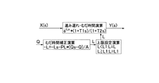
前記タイミング調整を行った熱媒供給量Q'wiへの修正は、進み遅れ要素を考慮するとともに、熱媒温度変化が温度計から熱交換コイル2に達するまでの時間遅れを考慮して行うこととするが、前記進み遅れ要素は線形1次微分方程式で表される要素となるため、制御一般で行われているように、前記進み遅れ要素とむだ時間要素との方程式をラプラス変換した伝達関数によって行うようにする。
The correction to the heating medium supply amount Q′wi that has been subjected to the timing adjustment should be made in consideration of the time delay until the temperature change of the heating medium reaches the
以下、順を追いながら前記伝達関数による熱媒供給量の修正方法(Q'wi)について具体的に詳述する。 Hereinafter, the heating medium supply amount correction method (Q′wi) based on the transfer function will be described in detail in order.
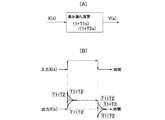
まず、進み遅れ演算をラプラス変換した伝達関数を下式(4)に示す。また、ブロック線図を図2(A)に示し、入出力の波形変化を図2(B)に示す。 First, a transfer function obtained by Laplace transforming the advance / delay calculation is shown in the following equation (4). A block diagram is shown in FIG. 2 (A), and input / output waveform changes are shown in FIG. 2 (B).
Y(s)=(1+T1s)/(1+T2s)*X(s) ……(4)
ここに、Y:出力、X:入力、T1:進み時定数、T2:遅れ時定数である。
Y (s) = (1 + T1s) / (1 + T2s) * X (s) (4)
Here, Y: output, X: input, T1: advance time constant, and T2: delay time constant.
図2(B)に示されるように、(i)T1=T2の時、タイミングの変化なし、(ii)T1>T2の時、タイミングを前に進める、(iii)T1<T2の時、タイミングを遅らすようにする。 As shown in FIG. 2B, (i) no change in timing when T1 = T2, (ii) advance timing when T1> T2, (iii) timing when T1 <T2. To delay.
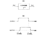
次いで、むだ時間演算をラプラス変換した伝達関数を下式(5)に示す。また、ブロック線図を図3(A)に示し、入出力の波形変化を図3(B)に示す。 Next, a transfer function obtained by Laplace transforming the dead time calculation is shown in the following equation (5). A block diagram is shown in FIG. 3 (A), and input / output waveform changes are shown in FIG. 3 (B).
Y(s)=e-Ls*X(s) ……(5)
ここに、Y:出力、X:入力、L:むだ時間である。
Y (s) = e- Ls * X (s) (5)
Here, Y: output, X: input, L: dead time.
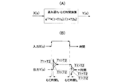
そして、前記進み遅れ演算とむだ時間演算の組み合わせをラプラス変換した伝達関数は下式(1)となる。また、ブロック線図を図4(A)に示し、入出力の波形変化を図4(B)に示す。 A transfer function obtained by performing Laplace transform on the combination of the advance / delay calculation and the dead time calculation is expressed by the following equation (1). A block diagram is shown in FIG. 4 (A), and input / output waveform changes are shown in FIG. 4 (B).
Y(s)=e-Ls*(1+T1s)/(1+T2s)*X(s) ……(1)
ここに、Y:出力、X:入力、T1:進み時定数、T2:遅れ時定数、L:むだ時間である。
Y (s) = e- Ls * (1 + T1s) / (1 + T2s) * X (s) (1)
Here, Y: output, X: input, T1: lead time constant, T2: delay time constant, and L: dead time.
前記T1、T2、Lの各パラメーターは、熱媒温度変化に対する送風温度変化またはコイル入口の熱媒温度変化と、バルブ開度変化に対する送風温度変化又はコイル入口の熱媒温度変化を見て調整する。ここで、T1はバルブの応答遅れを示す時間定数、T2は熱媒温度変化の応答遅れを示す時定数、Lは熱媒温度変化が温度計から熱交換コイル2に達するまでの時間遅れとなる。
The parameters T1, T2, and L are adjusted by looking at the change in the blowing air temperature or the change in the heating medium temperature at the coil inlet with respect to the change in the heating medium temperature, and the change in the blowing temperature or the heating medium temperature at the coil inlet with respect to the valve opening change . Here, T1 is a time constant indicating a response delay of the valve, T2 is a time constant indicating a response delay of the heat medium temperature change, and L is a time delay until the heat medium temperature change reaches the
ところで、前記むだ時間Lについては、ブリードイン配管と熱媒温度計11との距離PLが離れていると配管内流速(Q/A:Aは配管断面積)の変化を受けて大きく変化するので、むだ時間Ls設定時の供給冷水量Qsに対する変化量(Qs-Q)を監視し補正を加えるようにするのが望ましい。具体的には、熱媒供給量が極めて小さいときにはむだ時間Lが必要以上に大きな値となってしまい、制御がかえって不安定になるので上限値L1を設けるようにする。その結果、図5に示されるブロック線図となる。
以上のタイミング調整を行った修正熱媒供給量Q'wiを熱媒循環系統Rに供給すべく、流量計13により流量を測定しながら制御弁12の開度調整を行うようにする。
By the way, the dead time L changes greatly when the distance PL between the bleed-in pipe and the
In order to supply the corrected heating medium supply amount Q′wi having the above timing adjustment to the heating medium circulation system R, the opening degree of the
1.試験目的
下表1に示されるように、本発明に係る改良シングル・ブリード・イン方式の空調装置1(実施例)、従来例に係る図9に示されるシングル・ブリード・イン方式の空調装置30A(比較例1)、図10に示されるダブル・ブリート・イン方式の空調装置30B(比較例2)において、以下の条件下で種々の外乱を発生させ、その際の室内温度の変化を測定することにより性能比較を行った。
1. Test Objectives As shown in Table 1 below, the improved single bleed-in type air conditioner 1 (Example) according to the present invention, and the single bleed-in
2.試験方法
試験条件は下表2とした。
2. Test method The test conditions are shown in Table 2 below.
〔実験1〕
外乱として熱源機器の容量制御による冷水温度変動を想定した試験を行った。具体的には、以下の条件で熱源送水温度設定を変動させるようにした。
・負荷率:80%(3600kcal/h)
・熱源送水温度変動:13℃から9℃に変動(変動幅:4℃、温度勾配1.5℃/min)
〔実験2〕
外乱として熱源側ポンプの変流量制御による冷水流量変動を想定した試験を行った。具体的には、以下の条件で熱源側のバルブを閉じて熱源供給流量を変動させるようにした。
・負荷率:80%(3600kcal/h)
・熱源供給流量変動:14(l/min)から12(l/min)に変動(変動幅:2 l/min)
〔実験3〕
外乱として、室内負荷を想定した試験を行った。電気ヒーターにより以下の負荷を与え、室内負荷を変動させる。
・負荷率:80%(3600kcal/h)
・部分負荷変動:±5%(±225kcal/h)周期28min
なお、制御機器のパラメータ設定は下表3のとおりとした。
[Experiment 1]
As a disturbance, a test was performed assuming a chilled water temperature fluctuation by controlling the capacity of the heat source equipment. Specifically, the heat source water supply temperature setting was varied under the following conditions.
・ Load factor: 80% (3600kcal / h)
・ Heat source water temperature fluctuation: fluctuates from 13 ℃ to 9 ℃ (variation width: 4 ℃, temperature gradient 1.5 ℃ / min)
[Experiment 2]
As a disturbance, a test was performed assuming a chilled water flow rate fluctuation by variable flow rate control of the heat source side pump. Specifically, the heat source supply flow rate was varied by closing the valve on the heat source side under the following conditions.
・ Load factor: 80% (3600kcal / h)
・ Heat source supply flow rate fluctuation: Fluctuation from 14 (l / min) to 12 (l / min) (fluctuation range: 2 l / min)
[Experiment 3]
As a disturbance, a test assuming an indoor load was performed. The following load is given by an electric heater to vary the indoor load.
・ Load factor: 80% (3600kcal / h)
・ Partial load fluctuation: ± 5% (± 225kcal / h) period 28min
The parameter settings for the control device are as shown in Table 3 below.
3.試験結果
〔実験1の結果〕
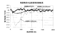
熱源側送水温度を変動させた場合の結果を下表4に示すとともに、その一部の結果を図6に示す。
3. Test result [Result of Experiment 1]
The results when the heat source side water supply temperature is varied are shown in Table 4 below, and part of the results are shown in FIG.
〔実験2の試験結果〕
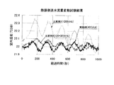
熱源側送水流量を変動させた場合の結果を下表5に示すとともに、その一部の結果を図7に示す。
[Test result of Experiment 2]
The results when the heat source side water supply flow rate is varied are shown in Table 5 below, and part of the results are shown in FIG.
注:改良シングル・ブリード・インは変動無し(無負荷状態での周期曲線に一致している。)
〔実験3の試験結果〕
室内の負荷を変動させた場合の結果を下表6に示すとともに、その一部の結果を図8に示す。
Note: Improved single bleed-in does not fluctuate (according to the no-load condition period curve)
[Test results of Experiment 3]
The results when the indoor load is varied are shown in Table 6 below, and some results are shown in FIG.
4.まとめ
(1)循環水量が増えれば、空調系の応答速度が増すため制御精度が上がるが、ある程度流量を増やすとその効果はほとんど差がない。
(2)ダブル・ブリード・インでは、冷水温度制御を途中に入れていることにより、シングル・ブリード・イン通常制御よりも温度制御精度が向上する。
(3)本発明に係る改良シングル・ブリード・イン方式では、シングル・ブリード・イン方式で循環水量を3倍にしたときよりも制御精度が高い。
(4)本発明に係る改良シングル・ブリード・イン方式は、循環水量を増やすことなく、ダブル・ブリード・インと同等、若しくはそれ以上の温度制御精度が得られる。特に外乱収束が速い。
(5)本発明に係る改良シングル・ブリード・イン方式は、熱源側流量変動の影響は全く受けない。
4). Summary (1) If the amount of circulating water increases, the response speed of the air conditioning system increases and the control accuracy increases. However, if the flow rate is increased to some extent, the effect is almost the same.
(2) In the double bleed-in, the temperature control accuracy is improved as compared with the single bleed-in normal control because the cold water temperature control is put in the middle.
(3) In the improved single bleed-in method according to the present invention, the control accuracy is higher than when the circulating water amount is tripled by the single bleed-in method.
(4) The improved single bleed-in method according to the present invention can provide temperature control accuracy equal to or higher than double bleed-in without increasing the amount of circulating water. Disturbance convergence is particularly fast.
(5) The improved single bleed-in method according to the present invention is not affected at all by the heat source side flow rate fluctuation.
1…空調装置、2…熱交換コイル、3…熱源、4…レタン管、5…サプライ管、8…バイパス管、10・11…熱媒温度計、16・18…熱量演算機器、19…熱量バランス演算機器、20…タイミング調整機器、21…流量制御機器、R…熱媒循環系統
DESCRIPTION OF
Claims (5)
室内温度計及び/又は給気温度計による計測温度に温度変化が生じたならば、前記温度変化を解消し元の設定温度に修正し得る前記熱交換コイルにおける熱交換量と、熱源から前記熱媒循環系統に供給される熱量とが等しくなるように、熱源から前記熱媒循環系統に供給すべき熱媒供給量を算出するとともに、この算出された熱媒供給量を、熱源からの熱媒温度変化の影響ズレを無くすようにタイミング調整を行った熱媒供給量に修正し、この修正熱媒供給量を前記熱媒循環系統に供給するように流量制御することを特徴とする空調方法。 A heat medium circulation system is formed around the heat exchange coil by a bypass connecting the supply path to the heat exchange coil and the reflux path from the heat exchange coil, and a part of the heat medium refluxed from the heat exchange coil is formed. In the air conditioning method of mixing with the heat medium supplied from the heat source and supplying the heat exchange coil again,
If a temperature change occurs in the temperature measured by the indoor thermometer and / or the supply air thermometer, the heat exchange amount in the heat exchange coil that can be corrected to the original set temperature by eliminating the temperature change, and the heat from the heat source. The heat medium supply amount to be supplied from the heat source to the heat medium circulation system is calculated so that the amount of heat supplied to the medium circulation system is equal, and the calculated heat medium supply amount is used as the heat medium supply from the heat source. An air conditioning method comprising correcting to a heating medium supply amount that has been subjected to timing adjustment so as to eliminate the influence of temperature change, and controlling the flow rate so that the corrected heating medium supply amount is supplied to the heating medium circulation system.
室内温度計及び/又は給気温度計による計測温度に温度変化が生じたならば、前記温度変化を解消し元の設定温度に修正するための前記熱交換コイルにおける熱交換量を求め、
前記熱交換コイルにおける熱交換量と、熱源から前記熱媒循環系統に供給される熱量とが等しくなる条件の熱量バランス方程式に基づいて、前記熱媒循環系統入側での熱媒温度、前記熱媒循環系統出側での熱媒温度および前記熱交換コイルにおける熱交換量とから、熱源から前記熱媒循環系統に供給すべき熱媒供給量を算出するとともに、この算出された熱媒供給量を、熱源からの熱媒温度変化の影響ズレを無くすようにタイミング調整を行った熱媒供給量に修正し、この修正熱媒供給量を前記熱媒循環系統に供給するように流量制御することを特徴とする空調方法。 A heat medium circulation system is formed around the heat exchange coil by a bypass connecting the supply path to the heat exchange coil and the reflux path from the heat exchange coil, and a part of the heat medium refluxed from the heat exchange coil is formed. In the air conditioning method of mixing with the heat medium supplied from the heat source and supplying the heat exchange coil again,
If a temperature change occurs in the temperature measured by the indoor thermometer and / or the supply air thermometer, the amount of heat exchange in the heat exchange coil for eliminating the temperature change and correcting to the original set temperature is obtained,
Based on the heat quantity balance equation under the condition that the heat exchange amount in the heat exchange coil and the heat quantity supplied from the heat source to the heat medium circulation system are equal, the heat medium temperature on the inlet side of the heat medium circulation system, the heat The heat medium supply amount to be supplied from the heat source to the heat medium circulation system is calculated from the heat medium temperature on the outlet side of the medium circulation system and the heat exchange amount in the heat exchange coil, and the calculated heat medium supply amount Is adjusted to a heat medium supply amount that is adjusted in timing so as to eliminate the influence of the change in temperature of the heat medium from the heat source, and the flow rate is controlled so that this corrected heat medium supply amount is supplied to the heat medium circulation system. An air conditioning method characterized by
室内温度計及び/又は給気温度計による計測温度に温度変化が生じたならば、前記温度変化を解消し元の設定温度に修正するための前記熱交換コイル入口での熱媒温度を求め、
前記熱交換コイルにおける熱交換量と、熱源から前記熱媒循環系統に供給される熱量とが等しくなる条件の熱量バランス方程式に基づいて、前記熱媒循環系統入側での熱媒温度、前記熱媒循環系統出側での熱媒温度、前記熱媒循環系統における循環熱媒量および前記熱交換コイル入口での熱媒温度とから、熱源から前記熱媒循環系統に供給すべき熱媒供給量を算出するとともに、この算出された熱媒供給量を、熱源からの熱媒温度変化の影響ズレを無くすようにタイミング調整を行った熱媒供給量に修正し、この修正熱媒供給量を前記熱媒循環系統に供給するように流量制御することを特徴とする空調方法。 A heat medium circulation system is formed around the heat exchange coil by a bypass connecting the supply path to the heat exchange coil and the reflux path from the heat exchange coil, and a part of the heat medium refluxed from the heat exchange coil is formed. In the air conditioning method of mixing with the heat medium supplied from the heat source and supplying the heat exchange coil again,
If a temperature change occurs in the temperature measured by the indoor thermometer and / or the supply air thermometer, obtain the heat medium temperature at the inlet of the heat exchange coil for eliminating the temperature change and correcting it to the original set temperature,
Based on the heat quantity balance equation under the condition that the heat exchange amount in the heat exchange coil and the heat quantity supplied from the heat source to the heat medium circulation system are equal, the heat medium temperature on the inlet side of the heat medium circulation system, the heat Heat medium supply amount to be supplied from the heat source to the heat medium circulation system from the heat medium temperature at the outlet side of the medium circulation system, the amount of the circulation heat medium in the heat medium circulation system and the heat medium temperature at the inlet of the heat exchange coil And the calculated heating medium supply amount is corrected to a heating medium supply amount that is adjusted in timing so as to eliminate the influence of the change in temperature of the heating medium from the heat source. An air conditioning method characterized by controlling a flow rate so as to be supplied to a heat medium circulation system.
Y(s)=e-Ls*(1+T1s)/(1+T2s)*X(s) ……(1)
ここに、Y:出力、X:入力、L:むだ時間、T1:進み時定数、T2:遅れ時定数とする。 The air-conditioning method according to any one of claims 1 to 3, wherein the correction to the heat medium supply amount that has been subjected to the timing adjustment is performed by a transfer function of the following (1) that combines a lead-lag element and a dead time element by Laplace conversion. .
Y (s) = e -Ls * (1 + T1s) / (1 + T2s) * X (s) ...... (1)
Here, Y: output, X: input, L: dead time, T1: lead time constant, T2: delay time constant.
前記熱媒循環系統入側に設置された熱媒温度計、熱媒循環系統出側に設置された熱媒温度計、室内に設置された室内温度計及び/又は吹出口部に設置された給気温度計からなる温度計測機器群と、
この室内温度計及び/又は給気温度計による計測温度に温度変化が生じたならば、前記温度変化を解消し元の設定温度に修正するための前記熱交換コイルにおける熱交換量又は前記熱交換コイル入口での熱媒温度を求めるための熱量演算機器と、
前記熱交換コイルにおける熱交換量と、熱源から前記熱媒循環系統に供給される熱量とが等しくなる条件の熱量バランス方程式に基づいて、前記熱媒循環系統入側での熱媒温度、前記熱媒循環系統出側での熱媒温度および前記熱交換コイルにおける熱交換量又は前記熱媒循環系統における循環熱媒量および前記熱交換コイル入口での熱媒温度とから、熱源から前記熱媒循環系統に供給すべき熱媒供給量を算出する熱量バランス演算機器と、
この算出された熱媒供給量を、熱源からの熱媒温度変化の影響ズレを無くすようにタイミング調整を行った熱媒供給量に修正するためのタイミング調整機器と、
この修正熱媒供給量を前記熱媒循環系統に供給するために前記熱媒の供給路に設けた制御弁を開度調整するための流量制御機器とからなることを特徴とする空調装置。
A heat medium circulation system is formed around the heat exchange coil by a bypass connecting the supply path to the heat exchange coil and the reflux path from the heat exchange coil, and a part of the heat medium refluxed from the heat exchange coil is formed. In the air conditioner mixed with the heat medium supplied from the heat source and re-supplied to the heat exchange coil,
Heat medium thermometer installed on the inlet side of the heat medium circulation system, heat medium thermometer installed on the outlet side of the heat medium circulation system, indoor thermometer installed indoors, and / or a supply installed in the outlet A temperature measuring device group consisting of a thermometer,
If a temperature change occurs in the temperature measured by the indoor thermometer and / or the supply air thermometer, the heat exchange amount in the heat exchange coil or the heat exchange for canceling the temperature change and correcting to the original set temperature A calorific value calculation device for obtaining the heat medium temperature at the coil inlet;
Based on the heat quantity balance equation under the condition that the heat exchange amount in the heat exchange coil and the heat amount supplied from the heat source to the heat medium circulation system are equal, the heat medium temperature on the inlet side of the heat medium circulation system, the heat The heat medium circulation from the heat source from the heat medium temperature on the outlet side of the medium circulation system and the heat exchange amount in the heat exchange coil or the amount of the circulation heat medium in the heat medium circulation system and the heat medium temperature at the inlet of the heat exchange coil A heat balance calculator that calculates the amount of heat medium to be supplied to the system;
A timing adjustment device for correcting the calculated heat medium supply amount to a heat medium supply amount that has been subjected to timing adjustment so as to eliminate the influence of the heat medium temperature change from the heat source;
An air conditioner comprising: a flow rate control device for adjusting the opening of a control valve provided in the supply path of the heat medium for supplying the corrected heat medium supply amount to the heat medium circulation system.
Priority Applications (1)
| Application Number | Priority Date | Filing Date | Title |
|---|---|---|---|
| JP2004109660A JP4521860B2 (en) | 2004-04-02 | 2004-04-02 | Air conditioning method and air conditioner |
Applications Claiming Priority (1)
| Application Number | Priority Date | Filing Date | Title |
|---|---|---|---|
| JP2004109660A JP4521860B2 (en) | 2004-04-02 | 2004-04-02 | Air conditioning method and air conditioner |
Publications (2)
| Publication Number | Publication Date |
|---|---|
| JP2005291652A true JP2005291652A (en) | 2005-10-20 |
| JP4521860B2 JP4521860B2 (en) | 2010-08-11 |
Family
ID=35324771
Family Applications (1)
| Application Number | Title | Priority Date | Filing Date |
|---|---|---|---|
| JP2004109660A Expired - Lifetime JP4521860B2 (en) | 2004-04-02 | 2004-04-02 | Air conditioning method and air conditioner |
Country Status (1)
| Country | Link |
|---|---|
| JP (1) | JP4521860B2 (en) |
Cited By (6)
| Publication number | Priority date | Publication date | Assignee | Title |
|---|---|---|---|---|
| CN103388878A (en) * | 2012-05-11 | 2013-11-13 | 四川优的科技有限公司 | Central air conditioner charging system |
| JP2013245861A (en) * | 2012-05-25 | 2013-12-09 | Ntt Facilities Inc | Water-cooled air conditioning system |
| JP2017003180A (en) * | 2015-06-09 | 2017-01-05 | 株式会社Nttファシリティーズ | Air conditioning system and air conditioning system program |
| CN112628859A (en) * | 2020-12-25 | 2021-04-09 | 珠海格力电器股份有限公司 | Air conditioner, control method and device of air conditioner and air conditioning system |
| CN115031356A (en) * | 2022-06-30 | 2022-09-09 | 深圳市英维克科技股份有限公司 | Variable frequency air conditioner control method and device, electronic equipment and medium |
| CN116972491A (en) * | 2023-08-24 | 2023-10-31 | 宁波奥克斯电气股份有限公司 | Surface cooler control method, device and air conditioner |
Citations (6)
| Publication number | Priority date | Publication date | Assignee | Title |
|---|---|---|---|---|
| JPH03247935A (en) * | 1990-02-27 | 1991-11-06 | Kajima Corp | Air-conditioner |
| JPH09166346A (en) * | 1995-12-14 | 1997-06-24 | Takasago Thermal Eng Co Ltd | Air conditioner, air conditioning system and control method thereof |
| JPH10281532A (en) * | 1997-04-04 | 1998-10-23 | Takenaka Komuten Co Ltd | Air conditioner |
| JPH10292942A (en) * | 1997-04-18 | 1998-11-04 | Sanken Setsubi Kogyo Kk | Automatic control method of air conditioning equipment |
| JP2001289482A (en) * | 2000-04-05 | 2001-10-19 | Hitachi Ltd | District cooling / heating operation system and its operation method |
| JP2004028476A (en) * | 2002-06-27 | 2004-01-29 | Sanki Eng Co Ltd | Air conditioning system with coil freezing prevention function |
-
2004
- 2004-04-02 JP JP2004109660A patent/JP4521860B2/en not_active Expired - Lifetime
Patent Citations (6)
| Publication number | Priority date | Publication date | Assignee | Title |
|---|---|---|---|---|
| JPH03247935A (en) * | 1990-02-27 | 1991-11-06 | Kajima Corp | Air-conditioner |
| JPH09166346A (en) * | 1995-12-14 | 1997-06-24 | Takasago Thermal Eng Co Ltd | Air conditioner, air conditioning system and control method thereof |
| JPH10281532A (en) * | 1997-04-04 | 1998-10-23 | Takenaka Komuten Co Ltd | Air conditioner |
| JPH10292942A (en) * | 1997-04-18 | 1998-11-04 | Sanken Setsubi Kogyo Kk | Automatic control method of air conditioning equipment |
| JP2001289482A (en) * | 2000-04-05 | 2001-10-19 | Hitachi Ltd | District cooling / heating operation system and its operation method |
| JP2004028476A (en) * | 2002-06-27 | 2004-01-29 | Sanki Eng Co Ltd | Air conditioning system with coil freezing prevention function |
Cited By (8)
| Publication number | Priority date | Publication date | Assignee | Title |
|---|---|---|---|---|
| CN103388878A (en) * | 2012-05-11 | 2013-11-13 | 四川优的科技有限公司 | Central air conditioner charging system |
| JP2013245861A (en) * | 2012-05-25 | 2013-12-09 | Ntt Facilities Inc | Water-cooled air conditioning system |
| JP2017003180A (en) * | 2015-06-09 | 2017-01-05 | 株式会社Nttファシリティーズ | Air conditioning system and air conditioning system program |
| CN112628859A (en) * | 2020-12-25 | 2021-04-09 | 珠海格力电器股份有限公司 | Air conditioner, control method and device of air conditioner and air conditioning system |
| CN112628859B (en) * | 2020-12-25 | 2022-05-27 | 珠海格力电器股份有限公司 | Air conditioner, control method and device of air conditioner and air conditioning system |
| CN115031356A (en) * | 2022-06-30 | 2022-09-09 | 深圳市英维克科技股份有限公司 | Variable frequency air conditioner control method and device, electronic equipment and medium |
| CN115031356B (en) * | 2022-06-30 | 2024-04-12 | 深圳市英维克科技股份有限公司 | Inverter air conditioner control method, device, electronic device and medium |
| CN116972491A (en) * | 2023-08-24 | 2023-10-31 | 宁波奥克斯电气股份有限公司 | Surface cooler control method, device and air conditioner |
Also Published As
| Publication number | Publication date |
|---|---|
| JP4521860B2 (en) | 2010-08-11 |
Similar Documents
| Publication | Publication Date | Title |
|---|---|---|
| US9874880B2 (en) | Device and method for controlling opening of a valve in an HVAC system | |
| US20090142717A1 (en) | Metering combustion control | |
| EP3488313B1 (en) | Reduction of the return temperature in district heating and increasing of the return temperature in district cooling | |
| CN111213013B (en) | Method and system for controlling valves in HVAC systems | |
| Schwingshackl et al. | LoLiMoT based MPC for air handling units in HVAC systems | |
| CN106091341A (en) | Air conditioner supplying natural wind temperature control method | |
| JP4521860B2 (en) | Air conditioning method and air conditioner | |
| Shao et al. | Investigation on weights setting rule for weights-based fuzzy logic control algorithm utilized in direct expansion air-conditioning systems | |
| JP2007071416A (en) | Reheat steam system of boiler, and control method of reheat steam temperature | |
| Henze et al. | Evaluation of temperature degradation in hydraulic flow networks | |
| CN105066341A (en) | Variable water temperature control system suitable for air conditioning secondary pump system | |
| CN102538150A (en) | Method for controlling multiple air conditioners through variable-parameter intelligent PID linkage | |
| Zeng et al. | Cooling/heating dual-stage actuators decoupling structure design and energy management strategy for thermostatic airflow control | |
| Yeh et al. | Incorporating fan control into air-conditioning systems to improve energy efficiency and transient response | |
| JP5719247B2 (en) | Control method of outside air conditioner | |
| CN115289520B (en) | Heat exchange station control method and system based on indoor temperature separation technology | |
| Al-Assadi et al. | Robust decentralized control of HVAC systems using H∞-performance measures | |
| CN107305082B (en) | Cooler system, intermediate water temperature acquisition method thereof and control method thereof | |
| JP3175100B2 (en) | Air conditioning control method | |
| CN112588333B (en) | Constant temperature and humidity test box controlled by multiple temperature zones and multi-mode rapid temperature and humidity control method | |
| CN111512093A (en) | Control system for HVAC including air handling unit and terminal unit and method of operating the same | |
| JPS60105933A (en) | Control method for wind tunnel test equipment | |
| CN117146344A (en) | Terminal unit for indoor air conditioning | |
| CN223191789U (en) | Single cooling source temperature and humidity independent control system | |
| CN121089215B (en) | Air balance adjustment method for air outlets of transregional air conditioning boxes of variable-air-volume air conditioner |
Legal Events
| Date | Code | Title | Description |
|---|---|---|---|
| A621 | Written request for application examination |
Free format text: JAPANESE INTERMEDIATE CODE: A621 Effective date: 20070122 |
|
| A977 | Report on retrieval |
Free format text: JAPANESE INTERMEDIATE CODE: A971007 Effective date: 20081215 |
|
| A131 | Notification of reasons for refusal |
Free format text: JAPANESE INTERMEDIATE CODE: A131 Effective date: 20090525 |
|
| A521 | Request for written amendment filed |
Free format text: JAPANESE INTERMEDIATE CODE: A523 Effective date: 20090722 |
|
| A131 | Notification of reasons for refusal |
Free format text: JAPANESE INTERMEDIATE CODE: A131 Effective date: 20100208 |
|
| A521 | Request for written amendment filed |
Free format text: JAPANESE INTERMEDIATE CODE: A523 Effective date: 20100406 |
|
| TRDD | Decision of grant or rejection written | ||
| A01 | Written decision to grant a patent or to grant a registration (utility model) |
Free format text: JAPANESE INTERMEDIATE CODE: A01 Effective date: 20100519 |
|
| A01 | Written decision to grant a patent or to grant a registration (utility model) |
Free format text: JAPANESE INTERMEDIATE CODE: A01 |
|
| A61 | First payment of annual fees (during grant procedure) |
Free format text: JAPANESE INTERMEDIATE CODE: A61 Effective date: 20100524 |
|
| R150 | Certificate of patent or registration of utility model |
Ref document number: 4521860 Country of ref document: JP Free format text: JAPANESE INTERMEDIATE CODE: R150 Free format text: JAPANESE INTERMEDIATE CODE: R150 |
|
| FPAY | Renewal fee payment (event date is renewal date of database) |
Free format text: PAYMENT UNTIL: 20130604 Year of fee payment: 3 |
|
| FPAY | Renewal fee payment (event date is renewal date of database) |
Free format text: PAYMENT UNTIL: 20130604 Year of fee payment: 3 |
|
| FPAY | Renewal fee payment (event date is renewal date of database) |
Free format text: PAYMENT UNTIL: 20140604 Year of fee payment: 4 |
|
| R250 | Receipt of annual fees |
Free format text: JAPANESE INTERMEDIATE CODE: R250 |
|
| R250 | Receipt of annual fees |
Free format text: JAPANESE INTERMEDIATE CODE: R250 |
|
| R250 | Receipt of annual fees |
Free format text: JAPANESE INTERMEDIATE CODE: R250 |
|
| R250 | Receipt of annual fees |
Free format text: JAPANESE INTERMEDIATE CODE: R250 |
|
| R250 | Receipt of annual fees |
Free format text: JAPANESE INTERMEDIATE CODE: R250 |
|
| R250 | Receipt of annual fees |
Free format text: JAPANESE INTERMEDIATE CODE: R250 |
|
| R250 | Receipt of annual fees |
Free format text: JAPANESE INTERMEDIATE CODE: R250 |
|
| R250 | Receipt of annual fees |
Free format text: JAPANESE INTERMEDIATE CODE: R250 |
|
| R250 | Receipt of annual fees |
Free format text: JAPANESE INTERMEDIATE CODE: R250 |
|
| R250 | Receipt of annual fees |
Free format text: JAPANESE INTERMEDIATE CODE: R250 |
|
| R250 | Receipt of annual fees |
Free format text: JAPANESE INTERMEDIATE CODE: R250 |
|
| EXPY | Cancellation because of completion of term |