JP2005291643A - Heat exchanger - Google Patents
Heat exchanger Download PDFInfo
- Publication number
- JP2005291643A JP2005291643A JP2004108926A JP2004108926A JP2005291643A JP 2005291643 A JP2005291643 A JP 2005291643A JP 2004108926 A JP2004108926 A JP 2004108926A JP 2004108926 A JP2004108926 A JP 2004108926A JP 2005291643 A JP2005291643 A JP 2005291643A
- Authority
- JP
- Japan
- Prior art keywords
- passage
- inlet
- heat transfer
- section
- downstream
- Prior art date
- Legal status (The legal status is an assumption and is not a legal conclusion. Google has not performed a legal analysis and makes no representation as to the accuracy of the status listed.)
- Pending
Links
Images
Landscapes
- Details Of Heat-Exchange And Heat-Transfer (AREA)
Abstract
【課題】圧力損失を低減させると共に伝熱チューブの入口が開口する流入ヘッダー内での流体の流れの均一性を向上させることが可能な熱交換器を提供する。
【解決手段】 熱交換器としてのラジエータ6の流入ヘッダーとしてのアッパータンク20は、冷却水の流れの下流に向かうにつれて連続的に拡大する拡開通路23を形成する拡開部21を有する。拡開通路23は、最上流通路断面23aである流入口24と、最下流通路断面23bとの間で、ラジエータコア30のチューブ列Cにおける伝熱チューブ31の配列方向A2において冷却水の流れの方向に連続的に拡大しており、配列方向A2での最下流通路断面23bの幅は、配列方向A2での流入口24の幅の2倍以上である。
【選択図】図2There is provided a heat exchanger capable of reducing pressure loss and improving fluid flow uniformity in an inflow header in which an inlet of a heat transfer tube is opened.
An upper tank (20) as an inflow header of a radiator (6) as a heat exchanger has an expanding portion (21) that forms an expanding passage (23) that continuously expands toward the downstream of the flow of cooling water. The expansion passage 23 is a flow of the cooling water in the arrangement direction A2 of the heat transfer tubes 31 in the tube row C of the radiator core 30 between the inlet 24 which is the most upstream passage section 23a and the most downstream passage section 23b. The width of the most downstream passage section 23b in the arrangement direction A2 is not less than twice the width of the inflow port 24 in the arrangement direction A2.
[Selection] Figure 2
Description
本発明は、ポンプで加圧された流体が流入する流入ヘッダーと、流入ヘッダー内の流体が流入する複数の伝熱チューブを有する伝熱コアとを備える熱交換器に関し、該熱交換器は、例えば内燃機関のラジエータである。 The present invention relates to a heat exchanger comprising an inflow header into which a fluid pressurized by a pump flows, and a heat transfer core having a plurality of heat transfer tubes into which the fluid in the inflow header flows, the heat exchanger comprising: For example, a radiator of an internal combustion engine.
圧力損失の低減を図った熱交換器として、例えば特許文献1に開示されたラジエータがある。このラジエータは、タンクとヘッダプレートとを備える。タンクのタンク本体には、外方に突出するように出入口管が設けられ、タンク本体と出入口管の内面同士が交る角部に、面取りが形成される。また、ヘッダプレートには、列を構成する複数の偏平管が、それぞれ、端部をタンク本体内に突出させるように接続される。そして、偏平管の突出端部に設けられる拡管部は、平坦部が円弧状に膨出する一対の湾曲部を有する。このため、面取りが形成されていることにより、タンクと出入口管の流路抵抗が小さくなり、さらに拡管部が一対の湾曲部を有しているとにより、タンクと偏平管の流路抵抗が小さくなる。
ところで、前記従来技術では、エンジンを冷却した後の水は、円筒状の入口管を経て、該入口管の通路面積に比べて急速に拡大する通路面積を有するタンク本体内に流入する。このとき、面取りが形成されているものの、面取りにより拡大される通路の拡がり幅は、入口管により形成される通路の幅よりも小さいため、面取りによる剥離防止機能が十分とはいえず、特に、入口管からタンク本体へ流入する水量が多い場合などには、タンク本体の壁での流れの剥離を防止することが困難になる。 In the prior art, the water after cooling the engine flows through the cylindrical inlet pipe into the tank body having a passage area rapidly expanding as compared with the passage area of the inlet pipe. At this time, although the chamfering is formed, the expansion width of the passage expanded by chamfering is smaller than the width of the passage formed by the inlet pipe, so the peeling prevention function by chamfering is not sufficient. When there is a large amount of water flowing into the tank body from the inlet pipe, it is difficult to prevent separation of the flow at the wall of the tank body.
また、剥離に起因するタンク本体内での水の流れの均一性の低下、すなわち水の流速や圧力の均一性の低下は、偏平管に流入する流量のバラツキを発生させて、ラジエータの放熱性能の低下を招来する。このようなタンク本体内での流れの不均一は、タンク本体の通路面積に比べて極めて小さい通路面積を有する偏平管の流路抵抗が大きいこと、すなわち偏平管での圧力損失が大きいことを利用することにより、多少改善される。しかしながら、ラジエータの圧力損失が大きくなると、水の圧送および吸引を行うポンプの作動能力を大きくする必要があることから、ポンプが大型化したり、ポンプの駆動動力が増加する。さらに、ポンプの作動能力を大きくしたとしても、通路面積が極めて小さい偏平管を流通する水の流量には限界があるため、入口管からの水の供給量を増加したとしても、偏平管を流れる流量が飽和して、偏平管での放熱量(伝熱量)も飽和する結果、ラジエータの所要の放熱性能が得られないことがある。 In addition, the deterioration of the water flow uniformity in the tank body due to separation, that is, the decrease in the water flow rate and pressure uniformity, causes variations in the flow rate flowing into the flat tube, and the radiator heat dissipation performance. Invite the decline. Such non-uniform flow in the tank body utilizes the fact that the flow resistance of a flat tube having a very small passage area compared to the passage area of the tank body is large, that is, the pressure loss in the flat tube is large. By doing so, it will be improved somewhat. However, when the pressure loss of the radiator increases, it is necessary to increase the operating capacity of the pump that pumps and sucks water, so that the pump becomes larger and the driving power of the pump increases. Furthermore, even if the operating capacity of the pump is increased, there is a limit to the flow rate of water flowing through the flat pipe with a very small passage area, so even if the amount of water supplied from the inlet pipe is increased, it flows through the flat pipe. As a result of the saturation of the flow rate and the amount of heat release (heat transfer amount) in the flat tube, the required heat dissipation performance of the radiator may not be obtained.
前記従来技術において、タンク本体内に突出している偏平管の入口では、入口に平行な方向である側方から水が流入して縮流が発生することにより、また偏平管の出口では、出口から流出した直後の水が拡散することにより、それぞれ圧力損失が生じる。 In the prior art, at the inlet of the flat tube projecting into the tank body, water flows in from the side parallel to the inlet to generate a contracted flow, and at the outlet of the flat tube, from the outlet. The water immediately after flowing out diffuses to cause pressure loss.
本発明は、このような事情に鑑みてなされたものであり、請求項1〜5記載の発明は、圧力損失を低減させると共に伝熱チューブの入口が開口する流入ヘッダー内での流体の流れの均一性を向上させることが可能な熱交換器を提供することを目的とする。そして、請求項2,3記載の発明は、圧力損失の一層の低減および流入ヘッダー内での流体の流れの均一性を一層向上させることを目的とし、請求項4,5記載の発明は、さらに、伝熱チューブによる圧力損失の一層の低減を図ることを目的とする。
The present invention has been made in view of such circumstances, and the inventions of
請求項1記載の発明は、ポンプにより加圧された流体が流入する流入口が形成された流入ヘッダーと、前記流入ヘッダー内の流体が流入する複数の伝熱チューブがチューブ列を構成して配列される伝熱コアと、前記各伝熱チューブから流入した流体が流出する流出口が形成された流出ヘッダーとを備える熱交換器において、前記流入ヘッダーは、流体の流れの下流に向かうにつれて連続的に拡大する拡開通路を形成する拡開部を有し、前記拡開通路は、最上流部での通路面積を規定する最上流通路断面と、最下流部での通路面積を規定する最下流通路断面との間で、前記チューブ列における前記伝熱チューブの配列方向において流体の流れの方向に連続的に拡大しており、前記配列方向での前記最下流通路断面の幅は、前記配列方向での前記最上流通路断面の幅の2倍以上である熱交換器である。 According to the first aspect of the present invention, an inflow header in which an inflow port into which fluid pressurized by a pump flows is formed, and a plurality of heat transfer tubes into which the fluid in the inflow header flows are arranged in a tube row. The heat exchanger includes a heat transfer core and an outflow header formed with an outflow port through which the fluid flowing in from each of the heat transfer tubes flows out, wherein the inflow header is continuous toward the downstream of the fluid flow. An expansion portion that forms an expansion passage that expands to the uppermost flow passage, and the expansion passage includes a most upstream passage cross section that defines a passage area in the most upstream portion and a most downstream portion that defines a passage area in the most downstream portion. Between the passage cross sections, the heat transfer tubes in the tube row are continuously expanded in the direction of fluid flow in the arrangement direction of the heat transfer tubes, and the width of the most downstream passage cross section in the arrangement direction is the arrangement direction. In the above A heat exchanger is more than twice the width of the upstream passage section.
これによれば、拡開通路は、最上流通路断面と、配列方向での幅が最上流通路断面の2倍以上となる最下流通路断面との間で、下流に向かうにつれて連続的に拡大するので、通路面積の増加による流れの剥離が広い範囲に渡って防止または抑制される。そして、最下流通路断面の配列方向での幅が最上流通路断面の2倍以上となるように形成されているので、流入ヘッダー内で比較的多くの伝熱チューブが存在する配列方向での流れの均一性が向上する。 According to this, the expansion passage continuously expands toward the downstream between the most upstream passage cross section and the most downstream passage cross section whose width in the arrangement direction is twice or more the cross section of the most upstream passage. Therefore, flow separation due to an increase in passage area is prevented or suppressed over a wide range. And since the width in the arrangement direction of the cross section of the most downstream passage is formed to be twice or more of the cross section of the most upstream passage, the flow in the arrangement direction in which a relatively large number of heat transfer tubes exist in the inflow header. Improves uniformity.
請求項2記載の発明は、請求項1記載の熱交換器において、すべての前記伝熱チューブの入口は、前記最下流通路断面により覆われる領域内に配置されるものである。 According to a second aspect of the present invention, in the heat exchanger according to the first aspect, the inlets of all the heat transfer tubes are arranged in a region covered by the cross section of the most downstream passage.
これによれば、拡開通路により流れの剥離が防止または抑制される領域に、伝熱コアのすべての伝熱チューブの入口が配置されるので、すべての伝熱チューブの入口に流入する流体の流れの均一性が向上する。 According to this, since the inlets of all the heat transfer tubes of the heat transfer core are arranged in the region where the flow separation is prevented or suppressed by the expansion passage, the fluid flowing into the inlets of all the heat transfer tubes Flow uniformity is improved.
請求項3記載の発明は、請求項2記載の熱交換器において、前記拡開通路は、拡がり角が、23°よりも小さいものである。 According to a third aspect of the present invention, in the heat exchanger according to the second aspect, the expansion passage has an expansion angle smaller than 23 °.
これによれば、拡開通路における通路の拡がりの割合が抑制されて、拡開通路での流体の剥離が一層抑制され、流入ヘッダー内での流れが一層均一化される。 According to this, the ratio of the expansion of the passage in the expansion passage is suppressed, fluid separation in the expansion passage is further suppressed, and the flow in the inflow header is made more uniform.
請求項4記載の発明は、請求項1ないし請求項3のいずれか1項記載の熱交換器において、前記各伝熱チューブの入口に隣接して、前記流入ヘッダー内の流体を前記入口に案内する入口案内部が設けられ、前記入口案内部は、前記入口に向かう流体を前記入口の形状に合うように徐々に収束させる案内面を有するものである。 According to a fourth aspect of the present invention, in the heat exchanger according to any one of the first to third aspects, the fluid in the inflow header is guided to the inlet adjacent to the inlet of each of the heat transfer tubes. An inlet guide portion is provided, and the inlet guide portion has a guide surface that gradually converges the fluid toward the inlet so as to match the shape of the inlet.
これによれば、伝熱チューブの入口に向かう流体は、入口案内部の案内面に案内されて、入口の形状に合うように徐々に収束した後、入口から流入して伝熱チューブ内を流れるので、伝熱チューブの入口付近での縮流の発生が確実に防止される。 According to this, the fluid heading to the inlet of the heat transfer tube is guided by the guide surface of the inlet guide portion and gradually converges so as to match the shape of the inlet, and then flows from the inlet and flows through the heat transfer tube. Therefore, the occurrence of contraction near the inlet of the heat transfer tube is reliably prevented.
請求項5記載の発明は、請求項1ないし請求項4のいずれか1項記載の熱交換器において、前記各伝熱チューブの出口に隣接して、前記出口からの流体を前記流出ヘッダー内で案内する出口案内部が設けられ、前記出口案内部は、前記出口から流出した直後の流体を徐々に拡散させる案内面を有するものである。 According to a fifth aspect of the present invention, in the heat exchanger according to any one of the first to fourth aspects, the fluid from the outlet is disposed in the outflow header adjacent to the outlet of each of the heat transfer tubes. An outlet guide part for guiding is provided, and the outlet guide part has a guide surface for gradually diffusing the fluid immediately after flowing out of the outlet.
これによれば、各伝熱チューブから流出した直後の流体は、出口案内部の案内面に案内されて、徐々に拡散した後、流出ヘッダー内で集合するので、出口から流出した流体の剥離が確実に防止される。 According to this, the fluid immediately after flowing out from each heat transfer tube is guided by the guide surface of the outlet guide part and gradually diffuses and then gathers in the outflow header, so that the fluid flowing out from the outlet is peeled off. It is surely prevented.
請求項1記載の発明によれば、次の効果が奏される。すなわち、最下流通路断面の配列方向での幅が最上流通路断面の2倍以上となる拡開通路により、流れの剥離が防止または抑制されるので、流入ヘッダー内での圧力損失が低減し、さらに流入ヘッダー内で比較的多くの伝熱チューブが存在する配列方向での流れの均一性が向上するので、伝熱チューブの入口が開口する流入ヘッダー内での流体の流れの均一性が向上し、熱交換器での伝熱性能が向上する。さらに、圧力損失が低減するため、ポンプを大型化することなく、熱交換器に供給する流体の流量を増加させることができるので、この点でも伝熱性能を向上させることができる。
According to invention of
請求項2記載の発明によれば、引用された請求項記載の発明の効果に加えて、次の効果が奏される。すなわち、伝熱コアのすべての伝熱チューブの入口に流入する流体の流れの均一性が向上するので、流入ヘッダーにおける圧力損失および流れの均一性に関する請求項1の効果が一層高められる。
According to invention of
請求項3記載の発明によれば、引用された請求項記載の発明の効果に加えて、次の効果が奏される。すなわち、拡開通路での流体の剥離が一層抑制され、流入ヘッダー内での流れが一層均一化されるので、流入ヘッダーにおける圧力損失および流れの均一性が一層向上する。
According to invention of
請求項4記載の発明によれば、引用された請求項記載の発明の効果に加えて、次の効果が奏される。すなわち、伝熱チューブの入口付近での縮流の発生が確実に防止されるので、伝熱チューブにおける圧力損失が低減する。 According to invention of Claim 4, in addition to the effect of the invention of the cited claim, there exists the following effect. That is, the occurrence of contraction near the inlet of the heat transfer tube is reliably prevented, so that the pressure loss in the heat transfer tube is reduced.
請求項5記載の発明によれば、引用された請求項記載の発明の効果に加えて、次の効果が奏される。すなわち、出口から流出した流体の剥離が確実に防止されるので、伝熱チューブにおける圧力損失が低減する。
According to the invention described in
以下、本発明の実施形態を図1〜図14を参照して説明する。
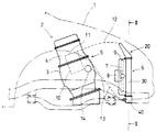
図1を参照すると、本発明の熱交換器であるラジエータ6は、車両1に搭載される水冷式内燃機関2に備えられる。車両1の前部に配置される内燃機関2は、ピストンが往復動可能に嵌合するシリンダが形成されたシリンダブロック3とシリンダブロック3の上端部に結合されるシリンダヘッド4とを有する機関本体5を備える。内燃機関2の冷却装置を構成するラジエータ6は、車両1の前部において機関本体5の前方に配置される。前記冷却装置は、ラジエータ6と、ラジエータ6の後方に配置される冷却ファン7とを備える。
Hereinafter, embodiments of the present invention will be described with reference to FIGS.
Referring to FIG. 1, a
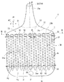
併せて図2,図3を参照すると、ラジエータ6は、機関本体5を冷却した後の高温の冷却水が機関本体5から流入する第1通路P1を形成する流入ヘッダーとしてのアッパータンク20と、アッパータンク20内の冷却水が流入する多数の第2通路P2をそれぞれ形成する多数の伝熱チューブ31からなるチューブ群を有する伝熱コアとしてのラジエータコア30と、各伝熱チューブ31からの冷却水が集合した後に機関本体5に向かって流出する第3通路を形成する流出ヘッダーとしてのロアタンク40とを備える。
2 and 3, the
電動モータ8により駆動される冷却ファン7は、ラジエータコア30の後面を覆うファンシュラウド9内に収容されて、前方からラジエータコア30の前面に向かう冷却風であるファン風を発生させて、車両1の走行時の冷却風である走行風と共に、ラジエータ6の周囲の外部流体である空気の強制対流によるラジエータコア30での伝熱を促進し、その放熱性能(冷却性能)を向上させる。
The cooling
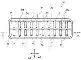
ラジエータコア30は、チューブ群と、各伝熱チューブ31を所定の配列状態に保持する保持部材としての第1,第2保持プレート32,33と、各伝熱チューブ31の外面に接触して設けられる薄板からなる波形の放熱フィン34とを備える。アッパータンク20とロアタンク40との間において上下方向に互いに平行に延びて配置される多数の伝熱チューブ31は、それぞれ、1対の対面する平板状で、互いに平行な管壁31w(図11〜図14も参照)を有し、該1対の管壁31wにより偏平な通路断面が形成される。チューブ群は、2列のチューブ列Cから構成され、各チューブ列Cにおいては、該チューブ列Cを構成する複数の伝熱チューブ31が、それぞれの1対の管壁31wが対面する方向である偏平方向に、整列した状態で配列されている。第1,第2保持プレート32,33は、後述する基準方向A1(各伝熱チューブ31の入口部31aにおける冷却水の流れ方向に平行な方向)から見て、チューブ列Cにおける伝熱チューブ31の配列方向A2(扁平方向でもある。)に長く、配列方向A2に直交する方向A3(以下、直交方向A3という。)に短い、ほぼ長方形である。また、放熱フィン34は、各伝熱チューブ31にろう付けにより接合される。
The
そして、シリンダヘッド4に形成された冷却水通路11の冷却水は、シリンダヘッド4とラジエータ6と連通させるパイプ12を経た後、ラジエータ6において、第1通路P1に流入し、次いで多数の第2通路P2を流通する間に伝熱チューブ31および放熱フィン34を通じて放熱して低温になった後、第3通路P3に流入する。第3通路P3の冷却水は、ラジエータ6とシリンダヘッド4またはシリンダブロック3に取り付けられるサーモスタット(図示されず)とを連通させるパイプ13を経てウォータポンプ14に導かれる。内燃機関2のクランク軸の動力により駆動されるウォータポンプ14により圧送された冷却水は、シリンダブロック3に形成された冷却水通路10および冷却水通路11を流通して、燃焼熱により高温となるシリンダブロック3およびシリンダヘッド4を冷却した後、パイプ12を経てラジエータ6に帰還する。
Then, the cooling water in the cooling water passage 11 formed in the cylinder head 4 passes through the
それゆえ、ラジエータ6においては、ポンプとしてのウォータポンプ14により加圧された流体である冷却水が、流入口24からアッパータンク20に流入し、次いで複数の伝熱チューブ31を流通した後、ロアタンク40に達し、ウォータポンプ14に吸引されることにより、ロアタンク40の流出口41から機関本体5に向けて流出する。
Therefore, in the
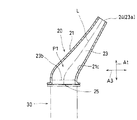
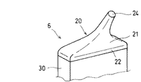
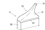
図2,図4,図5を参照すると、アッパータンク20は、通路面積が冷却水の流れの下流に向かって連続的に増加する拡開通路23を形成する拡開部21と、拡開部21に連なって形成されてラジエータコア30に接続される接続部22とを有する。
なお、この明細書において、「上流」および「下流」は、それぞれ、冷却水の流れに関しての「上流」および「下流」を意味する。
Referring to FIGS. 2, 4, and 5, the
In this specification, “upstream” and “downstream” mean “upstream” and “downstream” with respect to the flow of cooling water, respectively.
拡開部21の上流端部は、この実施形態では、パイプ12(図1参照)に接続される流入部21aを構成し、流入部21aには、シリンダヘッド4からの冷却水がラジエータ6に流入する流入口24が形成される。それゆえ、拡開通路23の最上流部での通路面積を規定する最上流通路断面23aが流入口24となる。また、拡開通路23の最下流部での通路面積を規定する最下流通路断面23b(便宜上、図2,図4に二点鎖線で示される。)は、拡開部21と接続部22との境界位置にあり、第1保持プレート32にほぼ平行であると共に第1保持プレート32とほぼ同じ形状である。
In this embodiment, the upstream end portion of the expanding
接続部22の通路面積は、第1通路P1における最大の通路面積であると共にその大きさがほぼ一定であり、最下流通路断面23bの通路面積は、後述する流出口25の通路面積でもある接続部22の通路面積とほぼ等しい。そして、接続部22には、アッパータンク20の、ラジエータコア30への冷却水の流出口25が形成される。この実施形態では、拡開通路23は、流出口25またはラジエータコア30を、配列方向A2で二等分する平面を対称面として形成される。
The passage area of the connecting
拡開通路23の通路壁面となる拡開部21の内面21cは、流入口24(最上流通路断面23a)と最下流通路断面23bとの間で実質的に流線形に形成される。ここで、流線形とは、内面21cから冷却水の流れの剥離または境界層の剥離が発生しにくい形状を意味する。また、実質的とは、内面21cにおいて、アッパータンク20に設けられる付属部、例えば冷却水の注入口やリザーブタンクとの接続口などのために、内面21cに形成される孔などが除かれ、かつ拡開通路23における冷却水全体の流れの状態に影響を殆ど及ぼさない局部的な凹凸や角部などが除かれることを意味する。
The
図3を併せて参照すると、拡開通路23は、流入口24と最下流通路断面23bとの間において、通路断面の周縁のすべての地点で、流入口24(最上流通路断面23a)付近の一部を除き、下流に向かうにつれて、すなわち冷却水の流れの方向に、連続的に拡大している。このため、拡開通路23は、配列方向A2に長い第1保持プレート32または配列方向A2に延びる各チューブ列Cに対応して、流入口24から最下流通路断面23bまで、配列方向A2において冷却水の流れの方向に連続的に拡大しており、配列方向A2での最下流通路断面23bの幅は、配列方向A2での流入口24の幅の2倍以上で、かつ前記直交方向A3での最下流通路断面23bの幅よりも大きい。
Referring also to FIG. 3, the
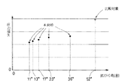
さらに、下流に向かっての拡開通路23の拡がりの程度を示す拡がり角θが、次式で定義されるとき、図6に示されるように、拡がり角θは、拡開部21の内面21cとの摩擦による冷却水の圧力損失が増加しない範囲で、拡開通路23の通路面積の増加による流れの剥離を抑制することにより圧力損失を低減する観点から、小さいほど好ましく、36°以下、より好ましくは23°よりも小さく設定される。
θ=2・tan−1(d2−d1/(2・L))
なお、式中、
d1:拡開通路23の流入口24の水力直径
d2:拡開通路23の最下流通路断面23bの水力直径
L :拡開通路23の中心線に沿った流入口24と最下流通路断面23bとの間の 距離(図4参照)
である。
Furthermore, when the expansion angle θ indicating the degree of expansion of the
θ = 2 · tan −1 (d2−d1 / (2 · L))
In the formula,
d1: Hydraulic diameter of the
d2: Hydraulic diameter of the most
L: Distance between the
It is.
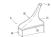
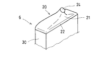
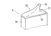
併せて、アッパータンク20の概略の外形が示される図5,図7〜図10を参照すると、配列方向A2での最下流通路断面23bの幅が配列方向A2での流入口24の幅の2倍よりも小さい拡開通路を有し、その拡がり角θが52°のアッパータンクを備えるラジエータ(比較対象)に比べて、本発明の実施形態であって、拡がり角θが、それぞれ、36°(図7参照)、23°(図8参照)、17°(図9参照)、13°(図10参照)および11°(図2,図4,図5参照)に設定されたアッパータンク20を備えるラジエータ6では、圧力損失が大幅に低減する。そして、拡がり角θが23°よりも小さいラジエータ6では、圧力損失は、一層低減し、しかも拡がり角θが小さくなるにつれて低減する。
In addition, referring to FIG. 5 and FIG. 7 to FIG. 10 in which the outline of the
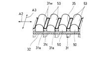
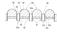
図2,図3,図11,図12を参照すると、第1通路P1内には、各伝熱チューブ31の入口部31aに形成される入口35に隣接して、アッパータンク20内の冷却水を入口35に案内する入口案内部を構成する案内部材50が、各伝熱チューブ31の上流端部31cを保持する第1保持プレート32に設けられる。案内部材50は、アッパータンク20内に開口する入口35よりも上流の冷却水を、入口35に向けて配列方向A2で徐々に収束するように案内する案内面53を有する。
Referring to FIGS. 2, 3, 11, and 12, in the first passage P <b> 1, the cooling water in the
案内部材50は、上流端部31cにおいて第1保持プレート32から第1通路P1に突出する入口部31aに隣接して第1保持プレート32に固定される。直交方向A3での入口35の幅とほぼ等しい幅を有する案内部材50は、第1保持プレート32から入口35までの突出量を有する基部51と、基部51に連なると共に入口35よりも上流に向かって突出する突出部52とを有する。そして、1つの入口35毎に、配列方向A2で入口35を挟むように1対の案内部材50が配置されることにより、案内部材50は、全体としては、配列方向A2での両端の入口35を除いて、配列方向A2で隣接する入口35の間に配置される。
The
各入口部31aの1対の管壁31wの外面に接する基部51は、配列方向A2で隣接する入口部31aの間のスペースを埋めている。また、突出部52に形成される流線形の案内面53は、配列方向A2および入口部31aでの流れ方向に平行な平面での断面形状が隣接する入口35の間隔にほぼ等しい直径のほぼ円弧となるように形成され、直交方向A3での入口35の幅とほぼ等しい幅を有する。
The
案内面53の最下流端部53bは、入口部31aの内面に極力滑らかに連なるように形成される。それゆえ、図12に二点鎖線で示されるように、案内面53と入口35との境界部に、伝熱チューブ31の厚みによる段差が生じることなく、案内面53と入口部31aの内面とが同一面で連続するように、案内面53が形成されてもよい。
The most
このため、案内面53よりも上流から入口35に向かう冷却水は、案内面53により入口35の形状に合うように徐々に収束する。そして、案内面53により案内された冷却水の流れは、各入口35において、少なくとも1対の管壁31wの、直交方向A3での幅全体に渡って、さらには入口35の、直交方向A3での幅のほぼ全体に渡って、案内面53の最下流端部53b、すなわち入口35の直上流で、入口部31aひいては伝熱チューブ31での流れの方向にほぼ一致する。
For this reason, the cooling water heading from the upstream side to the
さらに、入口部31aでの冷却水の流れ方向(この実施形態では、第2通路P2全体での冷却水の流れ方向に一致する。)に平行な方向を基準方向A1とするとき、最下流通路断面23bは、基準方向A1に直交する断面であり、しかも第1保持プレート32とほぼ同じ大きさであることから、基準方向A1で見て、各伝熱チューブ31の入口35は最下流通路断面23bの範囲内に配置される。したがって、すべての伝熱チューブ31の入口35は、基準方向A1において最下流通路断面23bにより覆われる領域内に配置される。
Furthermore, when the direction parallel to the flow direction of the cooling water at the
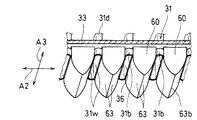
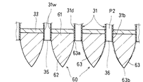
図2,図13,図14を参照すると、第3通路P3内には、各伝熱チューブ31の出口部31bに形成される出口36に隣接して、出口36から流入した冷却水をロアタンク40内で案内する出口案内部を構成する案内部材60が、各伝熱チューブ31の下流端部31dを保持する第2保持プレート33に設けられる。案内部材60は、ロアタンク40内に開口する出口36から流出した冷却水を配列方向A2で徐々に拡散させるように案内する案内面63を有する。
Referring to FIGS. 2, 13, and 14, the cooling water flowing from the
案内部材60は、下流端部31dにおいて第2保持プレート33から第3通路P3に突出する出口部31bに隣接して第2保持プレート33に固定される。直交方向A3での出口36の幅とほぼ等しい幅を有する案内部材60は、第2保持プレート33から出口36までの突出量を有する基部61と、基部61に連なると共に出口36よりも下流に向かって突出する突出部62とを有する。
The
案内部材60は、入口35に対する案内部材50の配置と同様に、出口36に対して配置される。すなわち、1つの出口36毎に、配列方向A2で出口36を挟むように1対の案内部材60が配置されることにより、案内部材60は、全体としては、配列方向A2での両端の出口36を除いて、配列方向A2で隣接する出口36の間に配置される。
The
管壁31wの外面に接する基部61は、配列方向A2で隣接する出口部31bの間のスペースを埋めている。また、突出部62に形成される流線形の案内面63は、配列方向A2および出口部31bでの流れ方向(この実施形態では、第2通路P2全体での冷却水の流れ方向に一致する。)に平行な平面での断面形状が、最下流端部63bに向かうにつれて先細となるほぼ紡錘形を形成するように、最下流端部63bを通り基準方向A1に平行な直線を対称線とする1対のほぼ円弧となるように形成され、直交方向A3での出口36の幅とほぼ等しい幅を有する。
The base 61 in contact with the outer surface of the
案内面63の最上流端部63aは、出口部31bの内面に極力滑らかに連なるように形成される。それゆえ、図14に二点鎖線で示されるように、案内面63と出口36との境界部に、伝熱チューブ31の厚みによる段差が生じることなく、案内面63と出口部31bの内面とが同一面で連続するように、案内面63が形成されてもよい。
The most
このため、出口36から流出した直後の冷却水の流れは、各出口36において、少なくとも1対の管壁31wの、直交方向A3での幅全体に渡って、さらには出口36の、直交方向A3での幅のほぼ全体に渡って、剥離することなく配列方向A2に拡散する。そして、下流端部では、冷却水の流れは、出口部31bでの流れ方向と同じ方向の速度成分を有することから、隣接する出口36からの冷却水と比較的滑らかに合流した後、ロアタンク40内で集合する。
For this reason, the flow of the cooling water immediately after flowing out of the
次に、前述のように構成された実施形態の作用および効果について説明する。
ラジエータ6のアッパータンク20は、冷却水の流れの下流に向かうにつれて連続的に拡大する拡開通路23を形成する拡開部21を有し、拡開通路23は、流入口24(最上流通路断面23a)と最下流通路断面23bとの間で、配列方向A2において流体の流れの方向に連続的に拡大しており、配列方向A2での最下流通路断面23bの幅は、配列方向A2での流入口24の幅の2倍以上であることにより、拡開通路23は、流入口24と、配列方向A2での幅が流入口24の2倍以上となる最下流通路断面23bとの間で、下流に向かうにつれて連続的に拡大するので、通路面積の増加による冷却水の流れの剥離が広い範囲に渡って防止または抑制されて、アッパータンク20内での圧力損失が低減する。そのうえ、最下流通路断面23bの配列方向A2での幅が流入口24の2倍以上となるように形成されているので、アッパータンク20内で比較的多くの伝熱チューブ31が存在する配列方向A2での流れの均一性が向上して、伝熱チューブ31の入口35が開口するアッパータンク20内での流れの均一性が向上し、ラジエータ6での放熱性能(伝熱性能)が向上する。
Next, operations and effects of the embodiment configured as described above will be described.
The
さらに、圧力損失が低減するため、ウォータポンプ14を大型化することなく、またウォータポンプ14の駆動動力の増加による燃費性能の低下を招くことなく、ラジエータ6に供給する冷却水の流量を増加させることができるので、この点でも放熱性能を向上させることができる。
Further, since the pressure loss is reduced, the flow rate of the cooling water supplied to the
ラジエータコア30のすべての伝熱チューブ31の入口35は、最下流通路断面23bにより覆われる領域内に配置されることにより、拡開通路23により流れの剥離が防止または抑制される領域に、ラジエータコア30のすべての伝熱チューブ31の入口35が配置されるので、すべての伝熱チューブ31の入口35に流入する流体の流れの均一性が向上して、アッパータンク20における圧力損失および流れの均一性が一層向上する。
The
最下流通路断面23bの通路面積は、第1通路P1における最大の通路面積である接続部22または流出口25の通路面積とほぼ等しいことにより、アッパータンク20における最大の範囲で拡開通路23が形成されるので、アッパータンク20での冷却水の流れの剥離が最大限に防止または抑制されて、アッパータンク20内での圧力損失がさらに低減し、流れの均一性がさらに向上する。
The passage area of the most
拡開通路23は、アッパータンク20の流出口25またはラジエータコア30を、配列方向A2で二等分する平面を対称面として形成されることにより、アッパータンク20内の流れの均一化が促進されるので、この点でもアッパータンク20内での流れの均一性が向上する。
The
拡開通路23の拡がり角θが、23°よりも小さいことにより、拡開通路23における通路の拡がりの割合が抑制されて、拡開通路23での流体の剥離が一層抑制され、アッパータンク20内での流れが一層均一化されるので、アッパータンク20における圧力損失および流れの均一性が一層向上する。
Since the expansion angle θ of the
各入口35に隣接して、アッパータンク20内の冷却水を入口35に案内する案内部材50が設けられ、案内部材50は、入口35に向かう冷却水を入口35の形状に合うように徐々に収束させる案内面53を有することにより、伝熱チューブ31の入口35に向かう流体は、案内部材50の案内面53に案内されて、入口35の形状に合うように配列方向A2で徐々に収束した後、入口35から流入して伝熱チューブ31内を流れるので、伝熱チューブ31の入口35付近での縮流の発生が確実に防止されて、伝熱チューブ31における圧力損失が低減する。
Adjacent to each
案内面53は、直交方向A3での入口35の幅とほぼ等しい幅を有することにより、案内面53により案内された冷却水の流れは、各入口35において、入口35の、直交方向A3での幅のほぼ全体に渡って収束するので、直交方向A3での幅の広い範囲に渡って縮流の発生が防止される。しかも、案内部材50は、配列方向A2で各入口35を挟むよう配置され、その基部51は、各入口部31aの1対の管壁31wの外面に接すると共に、配列方向A2で隣接する入口部31aの間のスペースを埋めていることにより、案内面53に案内された冷却水の流れの方向は、各入口35の直上流で、入口部31aひいては伝熱チューブ31での流れの方向にほぼ一致するので、この点でも縮流の発生が防止され、圧力損失が低減する。
The
各伝熱チューブ31の出口36に隣接して、出口36からの流体をロアタンク40内で案内する案内部材60が設けられ、案内部材60は、出口36から流出した直後の流体を配列方向A2で徐々に拡散させる案内面63を有することにより、各伝熱チューブ31から流出した直後の流体は、案内部材60の案内面63に案内されて、徐々に拡散した後、ロアタンク40内で集合するので、出口36から流出した流体の剥離が確実に防止されて、伝熱チューブ31における圧力損失が低減する。
Adjacent to the
案内面63は、直交方向A3での出口36の幅とほぼ等しい幅を有することにより、案内面63により案内された冷却水の流れは、各出口36において、出口36の、直交方向A3での幅のほぼ全体に渡って拡散するので、直交方向A3での幅の広い範囲に渡って剥離の発生が防止される。しかも、案内部材60は、配列方向A2で各出口36を挟むよう配置され、その基部61は、各出口部31bの1対の管壁31wの外面に接すると共に、配列方向A2で隣接する出口部31bの間のスペースを埋めており、案内面63は、最下流端部63bでの冷却水の流れが出口部31bでの流れ方向と同じ方向の速度成分を有するように、最下流端部63bに向かうにつれて先細となるほぼ紡錘形を形成するように形成されていることにより、各出口36から流出する冷却水は、隣接する出口36からの冷却水と比較的滑らかに合流した後、ロアタンク40内で集合するので、この点でも圧力損失が低減する。
Since the
以下、前述した実施形態の一部の構成を変更した実施形態について、変更した構成に関して説明する。
アッパータンク20において、流入口24と最上流通路断面23aとが別個に形成され、流入口24が、拡開通路23の最上流通路断面23aよりも上流側に位置していてもよい。また、拡開通路23は、アッパータンク20の流出口25またはラジエータコア30に対して、配列方向A2で面対称に配置されていなくてもよい。さらに、接続部22が拡開部21の一部により構成されてもよく、拡開部21は、複数の部材が接続されることにより形成されてもよい。チューブ群は、1列のチューブ列または3列以上のチューブ列により構成されてもよい。
Hereinafter, an embodiment in which a part of the configuration of the above-described embodiment is changed will be described with respect to the changed configuration.
In the
前記実施形態では、最下流通路断面23bはラジエータコア30のすべての伝熱チューブ31の入口35を覆っていたが、最下流通路断面23bがラジエータコア30のチューブ群を構成する一部の伝熱チューブ31の入口35を基準方向A1で覆うように、拡開通路23が形成されてもよい。
In the above embodiment, the most downstream
入口案内部または出口案内部は、第1保持プレート32または第2保持プレート33に一体成形されることにより設けられてもよい。ラジエータは、上下方向に直交する方向に、流入ヘッダーとしての流入タンクおよび流出ヘッダーとしての流出タンクを備える型式のものであってもよい。熱交換器は、水冷式内燃機関のラジエータであったが、ラジエータ以外の熱交換器であってもよい。
The inlet guide portion or the outlet guide portion may be provided by being integrally formed with the first holding
1…車両、2…内燃機関、3…シリンダブロック、4…シリンダヘッド、5…機関本体、6…ラジエータ、7…冷却ファン、8…電動モータ、9…ファンシュラウド、10,11…冷却水通路、12,13…パイプ、14…ウォータポンプ、
20…アッパータンク、21…拡開部、22…接続部、23…拡開通路、23a…最上流通路断面,23b…最下流通路断面、24…流入口、25…流出口、
30…ラジエータコア、31…伝熱チューブ、32,33…保持プレート、34…放熱フィン、35…入口、36…出口、
40…ロアタンク、41…流出口、
50,60…案内部材、51,61…基部、52,62…突出部、53,63…案内面、
P1,P2,P3…通路、C…チューブ列、A1…基準方向、A2…配列方向、A3…直交方向。
DESCRIPTION OF
20 ... Upper tank, 21 ... Expanded part, 22 ... Connecting part, 23 ... Expanded passage, 23a ... Cross-flow passage cross section, 23b ... Cross-flow passage cross section, 24 ... Inlet, 25 ... Outlet,
30 ... Radiator core, 31 ... Heat transfer tube, 32, 33 ... Holding plate, 34 ... Radiation fin, 35 ... Inlet, 36 ... Outlet,
40 ... Lower tank, 41 ... Outlet,
50, 60 ... guide member, 51, 61 ... base, 52, 62 ... protrusion, 53, 63 ... guide surface,
P1, P2, P3 ... passage, C ... tube row, A1 ... reference direction, A2 ... arrangement direction, A3 ... orthogonal direction.
Claims (5)
前記流入ヘッダーは、流体の流れの下流に向かうにつれて連続的に拡大する拡開通路を形成する拡開部を有し、前記拡開通路は、最上流部での通路面積を規定する最上流通路断面と、最下流部での通路面積を規定する最下流通路断面との間で、前記チューブ列における前記伝熱チューブの配列方向において流体の流れの方向に連続的に拡大しており、前記配列方向での前記最下流通路断面の幅は、前記配列方向での前記最上流通路断面の幅の2倍以上であることを特徴とする熱交換器。 An inflow header in which an inflow port into which a fluid pressurized by a pump flows is formed; a heat transfer core in which a plurality of heat transfer tubes into which the fluid in the inflow header flows in are arranged in a tube row; and In a heat exchanger comprising an outflow header formed with an outflow port through which the fluid flowing in from each heat transfer tube flows out,
The inflow header has an expanded portion that forms an expanded passage that continuously expands toward the downstream of the fluid flow, and the expanded passage defines a passage area in the most upstream portion. Between the cross section and the most downstream passage cross section that defines the passage area in the most downstream portion, the arrangement is continuously expanded in the direction of fluid flow in the arrangement direction of the heat transfer tubes in the tube row. The width of the cross section of the most downstream passage in the direction is at least twice the width of the cross section of the most upstream path in the arrangement direction.
θ=2・tan−1(d2−d1/(2・L))
ここで
θ :拡がり角
d1:拡開通路の最上流通路断面の水力直径
d2:拡開通路の最下流通路断面の水力直径
L :拡開通路の中心線に沿った最上流通路断面と最下流通路断面との間 の距離 The heat exchanger according to claim 2, wherein the expansion passage has an expansion angle obtained by the following expression smaller than 23 °.
θ = 2 · tan −1 (d2−d1 / (2 · L))
here
θ: divergence angle
d1: Hydraulic diameter of the cross section of the uppermost stream of the expansion passage
d2: Hydraulic diameter of the most downstream cross section of the expansion passage
L: Distance between the cross section of the most upstream path and the cross section of the most downstream path along the center line of the expansion path
Priority Applications (1)
| Application Number | Priority Date | Filing Date | Title |
|---|---|---|---|
| JP2004108926A JP2005291643A (en) | 2004-04-01 | 2004-04-01 | Heat exchanger |
Applications Claiming Priority (1)
| Application Number | Priority Date | Filing Date | Title |
|---|---|---|---|
| JP2004108926A JP2005291643A (en) | 2004-04-01 | 2004-04-01 | Heat exchanger |
Publications (1)
| Publication Number | Publication Date |
|---|---|
| JP2005291643A true JP2005291643A (en) | 2005-10-20 |
Family
ID=35324762
Family Applications (1)
| Application Number | Title | Priority Date | Filing Date |
|---|---|---|---|
| JP2004108926A Pending JP2005291643A (en) | 2004-04-01 | 2004-04-01 | Heat exchanger |
Country Status (1)
| Country | Link |
|---|---|
| JP (1) | JP2005291643A (en) |
Cited By (3)
| Publication number | Priority date | Publication date | Assignee | Title |
|---|---|---|---|---|
| JP2013249971A (en) * | 2012-05-30 | 2013-12-12 | Keihin Thermal Technology Corp | Heat exchanger |
| US20170038162A1 (en) * | 2015-08-06 | 2017-02-09 | Denso International America, Inc. | Flow Funneling Insert And Heat Exchanger With Flow Funneling Element |
| JP2017187183A (en) * | 2016-04-01 | 2017-10-12 | 三菱電機株式会社 | Heat exchanger and air conditioning device |
-
2004
- 2004-04-01 JP JP2004108926A patent/JP2005291643A/en active Pending
Cited By (7)
| Publication number | Priority date | Publication date | Assignee | Title |
|---|---|---|---|---|
| JP2013249971A (en) * | 2012-05-30 | 2013-12-12 | Keihin Thermal Technology Corp | Heat exchanger |
| US20170038162A1 (en) * | 2015-08-06 | 2017-02-09 | Denso International America, Inc. | Flow Funneling Insert And Heat Exchanger With Flow Funneling Element |
| JP2017036907A (en) * | 2015-08-06 | 2017-02-16 | デンソー インターナショナル アメリカ インコーポレーテッド | Heat exchanger and its insert parts |
| CN106438006A (en) * | 2015-08-06 | 2017-02-22 | 电装国际美国公司 | Flow Funneling Insert And Heat Exchanger With Flow Funneling Element |
| US10247490B2 (en) * | 2015-08-06 | 2019-04-02 | Denso International America, Inc. | Flow funneling insert and heat exchanger with flow funneling element |
| CN106438006B (en) * | 2015-08-06 | 2019-11-08 | 电装国际美国公司 | Heat exchanger and insertion section for heat exchanger |
| JP2017187183A (en) * | 2016-04-01 | 2017-10-12 | 三菱電機株式会社 | Heat exchanger and air conditioning device |
Similar Documents
| Publication | Publication Date | Title |
|---|---|---|
| US10107171B2 (en) | Cooling structure of internal combustion engine | |
| US8651170B2 (en) | Exhaust gas heat exchanger | |
| KR20180104936A (en) | Structure of duct for cooling brake | |
| JPWO2009069578A1 (en) | Liquid cooling system | |
| US10247490B2 (en) | Flow funneling insert and heat exchanger with flow funneling element | |
| JP2010223508A (en) | Intercooler for vehicle engine | |
| JP2004124945A (en) | Water jacket for cylinder head | |
| JPH1113551A (en) | EGR cooler | |
| JP2010209878A (en) | Egr cooler | |
| JP2017141844A (en) | EGR cooling device | |
| JP2003090693A (en) | Exhaust heat exchanger | |
| CN111148961B (en) | Exhaust gas heat exchanger | |
| CN107917012A (en) | Water jacket for cylinder head | |
| JP6577282B2 (en) | Heat exchanger | |
| JP5644258B2 (en) | Exhaust port structure | |
| JP2002180915A (en) | EGR cooler | |
| CN206386201U (en) | EGR channel | |
| CN216110970U (en) | Radiator and all-terrain vehicle | |
| KR101251260B1 (en) | Oil Cooler | |
| JP6195024B2 (en) | Exhaust device for 4-cylinder internal combustion engine | |
| JP3958302B2 (en) | Heat exchanger | |
| JP2016145524A (en) | EGR cooler | |
| EP2317271A1 (en) | U-flow radiator having an end tank with a Z-shape separator | |
| JP2008014263A (en) | Internal combustion engine cooling structure and cylinder head gasket used for the cooling structure | |
| JP4126946B2 (en) | Cylinder head structure of internal combustion engine |
Legal Events
| Date | Code | Title | Description |
|---|---|---|---|
| A621 | Written request for application examination |
Free format text: JAPANESE INTERMEDIATE CODE: A621 Effective date: 20061128 |
|
| RD04 | Notification of resignation of power of attorney |
Free format text: JAPANESE INTERMEDIATE CODE: A7424 Effective date: 20090428 |
|
| A977 | Report on retrieval |
Free format text: JAPANESE INTERMEDIATE CODE: A971007 Effective date: 20090617 |
|
| A131 | Notification of reasons for refusal |
Effective date: 20090630 Free format text: JAPANESE INTERMEDIATE CODE: A131 |
|
| A02 | Decision of refusal |
Effective date: 20091027 Free format text: JAPANESE INTERMEDIATE CODE: A02 |