JP2005291624A - Multitubular heat exchanger - Google Patents
Multitubular heat exchanger Download PDFInfo
- Publication number
- JP2005291624A JP2005291624A JP2004107237A JP2004107237A JP2005291624A JP 2005291624 A JP2005291624 A JP 2005291624A JP 2004107237 A JP2004107237 A JP 2004107237A JP 2004107237 A JP2004107237 A JP 2004107237A JP 2005291624 A JP2005291624 A JP 2005291624A
- Authority
- JP
- Japan
- Prior art keywords
- liquid
- pipe
- pipes
- liquid circulation
- treated
- Prior art date
- Legal status (The legal status is an assumption and is not a legal conclusion. Google has not performed a legal analysis and makes no representation as to the accuracy of the status listed.)
- Granted
Links
- 239000007788 liquid Substances 0.000 claims abstract description 303
- 238000003860 storage Methods 0.000 claims abstract description 95
- 239000007787 solid Substances 0.000 claims abstract description 53
- 238000009826 distribution Methods 0.000 claims description 67
- 238000011144 upstream manufacturing Methods 0.000 claims description 15
- 238000005304 joining Methods 0.000 description 18
- 239000011343 solid material Substances 0.000 description 18
- 239000000126 substance Substances 0.000 description 9
- 238000004891 communication Methods 0.000 description 8
- 238000004140 cleaning Methods 0.000 description 6
- 238000005406 washing Methods 0.000 description 5
- 238000001816 cooling Methods 0.000 description 4
- 238000010438 heat treatment Methods 0.000 description 4
- 238000009825 accumulation Methods 0.000 description 3
- 239000006185 dispersion Substances 0.000 description 3
- 235000015203 fruit juice Nutrition 0.000 description 3
- 238000005452 bending Methods 0.000 description 2
- 230000003247 decreasing effect Effects 0.000 description 2
- 239000000835 fiber Substances 0.000 description 2
- 230000008878 coupling Effects 0.000 description 1
- 238000010168 coupling process Methods 0.000 description 1
- 238000005859 coupling reaction Methods 0.000 description 1
- 230000007257 malfunction Effects 0.000 description 1
- 238000000034 method Methods 0.000 description 1
- 230000002093 peripheral effect Effects 0.000 description 1
Images


Classifications
-
- F—MECHANICAL ENGINEERING; LIGHTING; HEATING; WEAPONS; BLASTING
- F28—HEAT EXCHANGE IN GENERAL
- F28F—DETAILS OF HEAT-EXCHANGE AND HEAT-TRANSFER APPARATUS, OF GENERAL APPLICATION
- F28F9/00—Casings; Header boxes; Auxiliary supports for elements; Auxiliary members within casings
- F28F9/26—Arrangements for connecting different sections of heat-exchange elements, e.g. of radiators
-
- F—MECHANICAL ENGINEERING; LIGHTING; HEATING; WEAPONS; BLASTING
- F28—HEAT EXCHANGE IN GENERAL
- F28D—HEAT-EXCHANGE APPARATUS, NOT PROVIDED FOR IN ANOTHER SUBCLASS, IN WHICH THE HEAT-EXCHANGE MEDIA DO NOT COME INTO DIRECT CONTACT
- F28D7/00—Heat-exchange apparatus having stationary tubular conduit assemblies for both heat-exchange media, the media being in contact with different sides of a conduit wall
- F28D7/16—Heat-exchange apparatus having stationary tubular conduit assemblies for both heat-exchange media, the media being in contact with different sides of a conduit wall the conduits being arranged in parallel spaced relation
-
- F—MECHANICAL ENGINEERING; LIGHTING; HEATING; WEAPONS; BLASTING
- F28—HEAT EXCHANGE IN GENERAL
- F28F—DETAILS OF HEAT-EXCHANGE AND HEAT-TRANSFER APPARATUS, OF GENERAL APPLICATION
- F28F19/00—Preventing the formation of deposits or corrosion, e.g. by using filters or scrapers
Landscapes
- Engineering & Computer Science (AREA)
- Physics & Mathematics (AREA)
- Thermal Sciences (AREA)
- Mechanical Engineering (AREA)
- General Engineering & Computer Science (AREA)
- Details Of Heat-Exchange And Heat-Transfer (AREA)
- Heat-Exchange Devices With Radiators And Conduit Assemblies (AREA)
Abstract
Description
本発明は、被処理液体を加熱又は冷却するために使用する多管式熱交換器に係り、特に、固形物を含む被処理液体を加熱又は冷却する場合に適した多管式熱交換器に関する。 The present invention relates to a multitubular heat exchanger used for heating or cooling a liquid to be treated, and more particularly to a multitubular heat exchanger suitable for heating or cooling a liquid to be treated containing solids. .
図14乃至及び図16に示すように、被処理液体を効率的に加熱又は冷却するために、従来より、加熱又は冷却用の熱交換媒体(符号30は熱交換媒体収納部を示す)を充填した収納管(シェル)31の内部に複数の液体流通管(チューブ)32を並列に配し、拡大管33やU字管34を介して各伝熱管32内に熱処理する液体を分配して流通させる方式の多管式熱交換器35が使用されている。
As shown in FIGS. 14 and 16, in order to efficiently heat or cool the liquid to be treated, conventionally, a heat exchange medium for heating or cooling (
ところで、熱処理する液体が固形物36を含む場合、例えば、果実ジュースのように「さのう」と称される所定長さの繊維を含むような場合においては、従来、上記複数の液体流通管32は、「さのう」のような繊維の長さ寸法よりも小さい間隔寸法Wに配置されていた。その結果、各伝熱管32に液体を分配して送り込む際に、その固形物36の両端が隣接する2つの伝熱管32内部に跨ってしまい、液流圧によって伝熱管32の先端部に設けられた端面閉止板37に押し付けられて堆積する場合があった。
By the way, when the liquid to be heat-treated includes the
上記のような状態になると、各伝熱管32の開口端部38の周囲に位置する上記端面閉止板37に固形物36が付着して堆積することとなる。従って、このような固形物36を端面閉止板37から除去する必要があるが、熱交換器35内に洗浄液を循環させて洗浄するだけでは上記固形物36を除去することができなかった。
従って、このような場合には、熱交換器35の外管31に接続された拡大管33やU字管34を取り外し、手洗いで固形物36を除去しなければならず、洗浄作業も極めて煩雑であるという不具合があった。
If it will be in the above states, the
Therefore, in such a case, the
なお、本出願人は、上記の不具合を解消しうる先行技術について調査したが、関連する先行技術文献を見出すことはできなかった。 In addition, although this applicant investigated the prior art which can eliminate said malfunction, it could not find the related prior art literature.
そこで、本発明は、熱交換器に接続された接続管を取り外し、端面閉止板に堆積した固形物を手洗いにより除去する必要のない多管式熱交換器の提供を課題とする。 Then, this invention makes it a subject to remove the connection pipe connected to the heat exchanger, and to provide the multi-tube heat exchanger which does not need to remove the solid substance deposited on the end surface closing plate by hand washing.
上記課題を解決するために、請求項1記載の本発明に係る多管式熱交換器は、互いに所定間隔を置いて軸方向に沿って配設され、被処理液体が内部を流通する複数の液体流通管と、これらの液体流通管の端部において上記複数の液体流通管の開口部が固定される閉止板と、上記閉止板が端部に固定され、上記閉止板を介して上記複数の液体流通管を内部に収納すると共に、上記液体流通管の間に封入された熱交換媒体を有する収納管とを備え、上記液体流通管内を流通する被処理液体を熱交換する多管式熱交換器であって、上記液体流通管は被処理液体内に含まれる固形物の長さ寸法よりも大きな間隔寸法により配置されていることを特徴とする。
In order to solve the above-mentioned problems, a multi-tube heat exchanger according to the present invention as set forth in
即ち、請求項1記載の本発明に係る多管式熱交換器にあっては、被処理液体が上記複数の液体流通管内に分配されて流入し、上記収納管内において各液体流通管の間に封入された熱交換媒体により加熱又は冷却されることになる。
そして、上記液体流通管は被処理液体内に含まれる固形物の長さ寸法よりも大きな間隔寸法により配置されていることから、固形物の両端が隣接する2つの液体流通管内へ跨って堆積するという事態がなく、いずれかの液体流通管内に流入して流れる。
That is, in the multitubular heat exchanger according to the first aspect of the present invention, the liquid to be treated is distributed and flows into the plurality of liquid circulation pipes, and between the liquid circulation pipes in the storage pipe. It is heated or cooled by the enclosed heat exchange medium.
And since the said liquid distribution pipe is arrange | positioned by the space | interval dimension larger than the length dimension of the solid substance contained in a to-be-processed liquid, the both ends of a solid substance accumulate over two adjacent liquid distribution pipes. There is no such a situation, and it flows into one of the liquid circulation pipes.
また、請求項2記載の本発明に係る多管式熱交換器は、上記収納管には、下流に至るに従って拡開するテーパが付された接合管が接続され、上記接合管を介して被処理液体が供給されることを特徴とする。 Further, in the multitubular heat exchanger according to the second aspect of the present invention, a joint pipe having a taper that expands toward the downstream is connected to the storage pipe, and the pipe is covered through the joint pipe. A treatment liquid is supplied.
即ち、請求項2記載の本発明に係る多管式熱交換器にあっては、被処理液体は接合管を介して上記液体流通管内へ流入することになる。そして、上記接合管は下流に至るに従って拡開するテーパが付されていることから、上記収納管より径の小さいパイプから接合管を介して収納管内の各液体流通管内へ被処理液体を供給することができる。 That is, in the multitubular heat exchanger according to the second aspect of the present invention, the liquid to be treated flows into the liquid circulation pipe through the joining pipe. And since the said joint pipe is taper which expands as it goes downstream, the to-be-processed liquid is supplied into each liquid distribution pipe in a storage pipe from a pipe with a diameter smaller than the said storage pipe via a joint pipe. be able to.
また、請求項3記載の本発明に係る多管式熱交換器は、上記収納管には、収納管内部に配置された複数の液体流通管にそれぞれ接合しうる分配管を介して被処理液体が供給されることを特徴とする。 According to a third aspect of the present invention, in the multitubular heat exchanger according to the present invention, the liquid to be treated is connected to the storage pipe via a distribution pipe that can be joined to a plurality of liquid circulation pipes arranged inside the storage pipe. Is provided.
即ち、請求項3記載の本発明に係る多管式熱交換器にあっては、被処理液体は各分配管を介して各液体流通管内へ流入することになる。そして、上記収納管の径が小さい場合に、各分配管の上流側端部を直径方向の外側に曲げることにより、その各分配管の入口間の間隔寸法を被処理液体に含まれる固形物の長さ寸法より大きくすることができる。 That is, in the multitubular heat exchanger according to the third aspect of the present invention, the liquid to be treated flows into each liquid circulation pipe via each distribution pipe. And when the diameter of the said storage pipe is small, the space | interval dimension between the inlets of each distribution pipe is made into the outside of a diameter direction by bending the upstream edge part of each distribution pipe to the outer side of a diameter direction. It can be larger than the length dimension.
また、請求項4記載の本発明に係る多管式熱交換器は、上記収納管には、収納管内部に配置された複数の液体流通管にそれぞれ接合しうる分配管が接合されると共に、上記分配管の上流側には下流に至るに従って拡開するテーパが付された接合管が接続され、上記接合管及び分配管を介して液体流通管に被処理液体が供給されることを特徴とする。
Further, in the multitubular heat exchanger according to the present invention as set forth in
即ち、請求項4記載の本発明に係る多管式熱交換器にあっては、被処理液体は各分配管及び接合管を介して各液体流通管内へ流入することになる。そして、径の小さいパイプから接合管を介して各分配管へ被処理液体を供給すると共に、各分配管から径の小さい収納管内に配された各液体流通管へ被処理液体を供給することができる。
That is, in the multi-tube heat exchanger according to the present invention as set forth in
また、請求項5記載の本発明に係る多管式熱交換器は、上記収納管の液体流通管の流入側端部には、収納管の直径方向に沿って旋回流を発生させうる旋回流発生部が設けられ、 上記旋回流発生部は、収納管と同一の軸方向を有する短円筒状の空隙を備え、複数の液体流通管の開口部を全て包含しうるように配設されていることを特徴とする。
The multitubular heat exchanger according to the present invention described in
即ち、請求項5記載の本発明に係る多管式熱交換器にあっては、旋回流発生部において複数の液体流通管の開口部を臨む位置に設けられた短円筒状の空隙で被処理液体を旋回させることにより、複数の液体流通管の開口部において固形物が堆積するのを防止するものである。
請求項6記載の発明にあっては、互いに所定間隔を置いて軸方向に沿って配設され、被処理液体が内部を流通する複数の液体流通管と、これらの液体流通管の端部において上記複数の液体流通管の開口部が固定される閉止板と、上記閉止板が端部に固定され、上記閉止板を介して上記複数の液体流通管を内部に収納すると共に、上記液体流通管の間に封入された熱交換媒体を有する収納管とを備え、上記液体流通管内を流通する被処理液体を熱交換する多管式熱交換器であって、上記収納管には、収納管内部に配置された複数の液体流通管にそれぞれ接合しうる分配管を介して被処理液体が供給されることを特徴とする。
また、請求項7記載の発明にあっては、互いに所定間隔を置いて軸方向に沿って配設され、被処理液体が内部を流通する複数の液体流通管と、これらの液体流通管の端部において上記複数の液体流通管の開口部が固定される閉止板と、上記閉止板が端部に固定され、上記閉止板を介して上記複数の液体流通管を内部に収納すると共に、上記液体流通管の間に封入された熱交換媒体を有する収納管とを備え、上記液体流通管内を流通する被処理液体を熱交換する多管式熱交換器であって、上記収納管には、収納管内部に配置された複数の液体流通管にそれぞれ接合しうる分配管が接合されると共に、上記分配管の上流側には下流に至るに従って拡開するテーパが付された接合管が接続され、上記接合管及び分配管を介して液体流通管に被処理液体が供給されることを特徴とする。
請求項8記載の発明にあっては、互いに所定間隔を置いて軸方向に沿って配設され、被処理液体が内部を流通する複数の液体流通管と、これらの液体流通管の端部において上記複数の液体流通管の開口部が固定される閉止板と、上記閉止板が端部に固定され、上記閉止板を介して上記複数の液体流通管を内部に収納すると共に、上記液体流通管の間に封入された熱交換媒体を有する収納管とを備え、上記液体流通管内を流通する被処理液体を熱交換する多管式熱交換器であって、上記収納管の液体流通管の流入側端部には、収納管の直径方向に沿って旋回流を発生させうる旋回流発生部が設けられ、上記旋回流発生部は、収納管と同一の軸方向を有する短円筒状の空隙を備え、複数の液体流通管の開口部を全て包含しうるように配設されていることを特徴とする。
That is, in the multi-tubular heat exchanger according to the present invention as set forth in
In the invention of
In the invention according to claim 7, a plurality of liquid circulation pipes arranged along the axial direction at a predetermined interval from each other and through which the liquid to be treated flows, and ends of these liquid circulation pipes A closing plate to which the openings of the plurality of liquid circulation pipes are fixed in the section, the closing plate is fixed to an end, the plurality of liquid circulation pipes are accommodated in the inside via the closing plate, and the liquid And a storage tube having a heat exchange medium sealed between the flow tubes, and is a multi-tube heat exchanger for exchanging heat of the liquid to be processed flowing in the liquid flow tube, A pipe that can be joined to each of a plurality of liquid flow pipes arranged inside the pipe is joined, and a joint pipe with a taper that expands toward the downstream is connected to the upstream side of the pipe, The liquid to be treated is supplied to the liquid flow pipe through the joint pipe and the distribution pipe. There characterized in that it is supplied.
In the invention according to
請求項1記載の本発明に係る多管式熱交換器は、互いに所定間隔を置いて軸方向に沿って配設され、被処理液体が内部を流通する複数の液体流通管と、これらの液体流通管の端部において上記複数の液体流通管の開口部が固定される閉止板と、上記閉止板が端部に固定され、上記閉止板を介して上記複数の液体流通管を内部に収納すると共に、上記液体流通管の間に封入された熱交換媒体を有する収納管とを備え、上記液体流通管内を流通する被処理液体を熱交換する多管式熱交換器であって、上記液体流通管は被処理液体内に含まれる固形物の長さ寸法よりも大きな間隔寸法により配置されていることから、固形物を含む被処理液体が各液体流通管内へ流入する際に、その固形物が隣接する2つの液体流通管の間へ跨って、液流圧により固着することを防止することができる。
従って、上記閉止板に固形物が密着して堆積しにくくなるので、熱交換器内に洗浄液を循環させるだけで容易に洗浄処理を行うことができ、従来のように、洗浄処理の際に、熱交換器に接続された管を取り外し、閉止板に堆積した固形物を手洗いにより除去するという煩雑さが解消される。その結果、固形物の堆積を防止することができる
The multitubular heat exchanger according to the first aspect of the present invention includes a plurality of liquid circulation pipes that are disposed along the axial direction at predetermined intervals and in which a liquid to be treated flows, and these liquids A closing plate to which the openings of the plurality of liquid circulation pipes are fixed at an end of the flow pipe, and the closing plate is fixed to the end, and the plurality of liquid flow pipes are housed inside via the closing plate. And a storage pipe having a heat exchange medium enclosed between the liquid circulation pipes, and a multi-tube heat exchanger for exchanging heat of the liquid to be treated flowing in the liquid circulation pipe, Since the pipes are arranged with an interval dimension larger than the length dimension of the solid matter contained in the liquid to be treated, when the liquid to be treated containing solid matter flows into each liquid circulation pipe, It straddles between two adjacent liquid flow pipes and is fixed by liquid flow pressure. It is possible to prevent that.
Therefore, since solids are less likely to adhere to and accumulate on the closing plate, it is possible to easily perform the cleaning process simply by circulating the cleaning liquid in the heat exchanger. The trouble of removing the pipe connected to the heat exchanger and removing the solid matter accumulated on the closing plate by hand washing is eliminated. As a result, solid matter accumulation can be prevented.
請求項2記載の本発明に係る多管式熱交換器は、上記収納管には、下流に至るに従って拡開するテーパが付された接合管が接続され、上記接合管を介して被処理液体が供給されることから、上記収納管へ被処理液体を供給するパイプの径が小さくても、上記接合管を介することにより、各液体流通管の入口の間隔寸法を、被処理液体に含まれる固形物の長さ寸法よりも容易に大きくすることができる。
In the multi-tube heat exchanger according to the present invention as set forth in
請求項3記載の本発明に係る多管式熱交換器は、上記収納管には、収納管内部に配置された複数の液体流通管にそれぞれ接合しうる分配管を介して被処理液体が供給されることから、上記収納管の径が小さくて各液体流通管の間隔を十分に取ることができなくとも、各分配管を介することにより、その各分配管の上流側端部を直径方向の外側に曲げて、各分配管の入口間の間隔寸法を被処理液体に含まれる固形物の長さ寸法より容易に大きくすることができる。
In the multitubular heat exchanger according to the present invention as set forth in
請求項4記載の本発明に係る多管式熱交換器は、上記収納管には、収納管内部に配置された複数の液体流通管にそれぞれ接合しうる分配管が接合されると共に、上記分配管の上流側には下流に至るに従って拡開するテーパが付された接合管が接続され、上記接合管及び分配管を介して液体流通管に被処理液体が供給されることから、上記収納管へ被処理液体を供給するパイプの径が小さく、かつ、上記収納管の径が小さくて各液体流通管の間隔を十分に取ることができなくとも、上記接合管及び上記分配管を介することにより、各分配管の入口の間隔寸法を、被処理液体に含まれる固形物の長さ寸法よりも容易に大きくすることができる。
In the multitubular heat exchanger according to the present invention as set forth in
請求項5記載の本発明に係る多管式熱交換器は、上記収納管の液体流通管の流入側端部には、収納管の直径方向に沿って旋回流を発生させうる旋回流発生部が設けられ、上記旋回流発生部は、収納管と同一の軸方向を有する短円筒状の空隙を備え、複数の液体流通管の開口部を全て包含しうるように配設されていることから、上記旋回流発生部において複数の液体流通管の開口部を臨む位置に設けられた短円筒状の空隙で被処理液体を旋回させることにより、複数の液体流通管の開口部において固形物が堆積するのを阻止することができるので、固形物の堆積により各液体流通管内への被処理液体の流入が阻害されるのを防止することができる。
請求項6記載の発明にあっては、上記収納管には、収納管内部に配置された複数の液体流通管にそれぞれ接合しうる分配管を介して被処理液体が供給されることから、各液体流通管の開口部間において被処理液体内の固定物が引っかかり堆積する、という事態そのものを防止することができる。
また、請求項7記載の発明にあっては、上記収納管には、収納管内部に配置された複数の液体流通管にそれぞれ接合しうる分配管が接合されると共に、上記分配管の上流側には下流に至るに従って拡開するテーパが付された接合管が接続され、上記接合管及び分配管を介して液体流通管に被処理液体が供給されることから、各液体流通管の開口部間において被処理液体内の固定物が引っかかり堆積する、という事態そのものを防止することができる。
また、請求項8記載の発明にあっては、上記収納管の液体流通管の流入側端部には、収納管の直径方向に沿って旋回流を発生させうる旋回流発生部が設けられ、上記旋回流発生部は、収納管と同一の軸方向を有する短円筒状の空隙を備え、複数の液体流通管の開口部を全て包含しうるように配設されていることから、上記旋回流発生部において複数の液体流通管の開口部を臨む位置に設けられた短円筒状の空隙で被処理液体を旋回させることにより、複数の液体流通管の開口部において固形物が堆積するのを阻止することができるので、固形物の堆積により各液体流通管内への被処理液体の流入が阻害されるのを防止することができる。
The multitubular heat exchanger according to the present invention as set forth in
In the invention according to
In the invention according to claim 7, the storage pipe is joined to a plurality of liquid flow pipes arranged inside the storage pipe, respectively, and is connected to the upstream side of the distribution pipe. Is connected to a joining pipe with a taper that expands toward the downstream, and the liquid to be treated is supplied to the liquid circulation pipe via the joining pipe and the distribution pipe. It is possible to prevent a situation in which a fixed object in the liquid to be treated is caught and accumulated in the meantime.
Further, in the invention according to
以下、図面を用いて本発明の実施の形態について説明する。
本実施形態に係る多管式熱交換器1は、図1乃至図9に示すように、互いに所定間隔を置いて軸方向に沿って配設され、被処理液体が内部を流通する複数の液体流通管2と、これらの液体流通管2の端部において上記複数の液体流通管2の開口端部3が固定される閉止板4と、上記閉止板4が端部に固定され、上記閉止板4を介して上記複数の液体流通管2を内部に収納すると共に、上記液体流通管2の間に封入された熱交換媒体を有する収納管6とを備え、上記液体流通管2内被処理液体を熱交換するものであって、上記複数の液体流通管2は被処理液体内に含まれる固形物36の長さ寸法よりも大きな間隔寸法を以て配置されている。
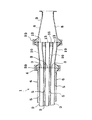
また、上記収納管6には、図1に示すように、下流に至るに従って拡開するテーパ8が付された接合管9が接続され、上記接合管9を介して被処理液体が供給されるように構成されている。
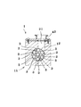
また、上記収納管6には、図3に示すように、収納管6内部に配置された複数の液体流通管2にそれぞれ接合しうる分配管10を介して被処理液体が供給されるように構成されている。
また、上記収納管6には、図5に示すように、収納管6内部に配置された複数の液体流通管2にそれぞれ接合しうる分配管10が接合されると共に、上記分配管10の上流側には下流に至るに従って拡開するテーパ8が付された接合管9が接続され、上記接合管9及び分配管10を介して液体流通管2に被処理液体が供給されるように構成されている。
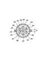
また、上記収納管6の液体流通管2の流入側端部には、図7及び図8に示すように、収納管6の直径方向に沿って旋回流を発生させうる旋回流発生部11が設けられ、上記旋回流発生部11は、収納管6と同一の軸方向を有する短円筒状の空隙12を備え、複数の液体流通管2の開口端部3を全て包含しうるように配設されている。
Hereinafter, embodiments of the present invention will be described with reference to the drawings.
As shown in FIGS. 1 to 9, the
Further, as shown in FIG. 1, a joining
Further, as shown in FIG. 3, the liquid to be treated is supplied to the
Further, as shown in FIG. 5, a
Further, as shown in FIGS. 7 and 8, a
図1及び図2に示した実施例1に係る多管式熱交換器1は、図1に示すように、収納管6の内部に、それぞれ被処理液体を内部に流通させる複数の液体流通管2が互いに所定間隔を置いて軸方向に沿って配設されている。
As shown in FIG. 1, the
上記液体流通管2は、図1に示すように、その端部において、その液体流通管2の開口端部3が閉止板4により固定されている。
As shown in FIG. 1, the
また、図1に示すように、上記閉止板4の内方であって、上記収納管6の内部における上記各液体流通管2の間の空隙及び収納管6の内表面と上記液体流通管2との間の空隙は熱交換媒体収納部5として形成され、この熱交換媒体収納部5には液体流通管2内を流通する被処理液体を加熱又は冷却する熱交換媒体が封入されている。
Further, as shown in FIG. 1, the inside of the
上記液体流通管2は、図2に示すように、その開口端部3が、被処理液体内に含まれる固形物36の長さ寸法よりも大きな間隔寸法Xにより配置されている。
なお、本実施例1では果実ジュースを被処理液体としているので、その果実ジュースに含まれる「さのう」と称される固形物36の長さ寸法がほぼ15mm以下であることから、上記間隔寸法Xは15mm以上に設定されている。
しかしながら、被処理液体が異なれば、被処理液体に含まれる固形物36の長さ寸法も増減するので、上記間隔寸法Xは被処理液体が異なれば、それに応じて当然増減して設定される。
As shown in FIG. 2, the
In addition, since fruit juice is used as the liquid to be treated in Example 1, the length of the
However, if the liquid to be treated is different, the length dimension of the
上記収納管6の上流側の端部には、図1に示すように、下流に至るに従って拡開するテーパ8が付された接合管9が接続されている。即ち、接合管9を介して被処理液体が各液体流通管2内へ供給されるように構成されている。
なお、接合管9は、図1に示すように、その鍔部41が閉止板4の鍔部40と共にクランプ部39により締め付けられて固定されている。
As shown in FIG. 1, a connecting
As shown in FIG. 1, the joining
上記接合管9の上流側には、図は省略するが、さらに液体供給パイプが接続されるが、この液体供給パイプの径が小さくても、上記テーパ8の角度を変えることにより、上記開口端部3の間隔寸法Xを十分に取ることができる。
Although not shown in the drawing, a liquid supply pipe is connected to the upstream side of the
上記接合管9から各液体流通管2内へ被処理液体が流入する際に、被処理液体に含まれる固形物36が、スムーズに液体流通管2内に流入せず、上記閉止板4上に当接し、液圧によりその位置に留まるという事態はありうる。
しかしながら、その固形物36の長さ寸法より開口端部3の間隔寸法Xは大きく設定されているので、固形物36の両端が隣接する2つの液体流通管2の内部に跨るようにして、閉止板4上に引っかかることはない。従って、洗浄液を熱交換器内に循環させるだけで固形物36は容易に除去され、閉止板4に堆積することはない。
When the liquid to be processed flows from the
However, since the gap dimension X of the
次に、図3及び図4に示した実施例2に係る多管式熱交換器1も、図3に示すように、収納管6の内部に、それぞれ被処理液体を内部に流通させる複数の液体流通管2が互いに所定間隔を置いて軸方向に沿って配設されている。
そして、上記液体流通管2は、図3に示すように、その端部において、その液体流通管2の開口端部3が閉止板4により固定されている。
また、図3に示すように、上記閉止板4の内方であって、上記収納管6の内部における上記各液体流通管2の間には、液体流通管2内を流通する被処理液体を加熱又は冷却する熱交換媒体(符号5が熱交換媒体収納部を示す)が封入されている。
以上の構造は上記実施例1と同一である。
Next, as shown in FIG. 3, the
As shown in FIG. 3, the
In addition, as shown in FIG. 3, the liquid to be treated that circulates in the
The above structure is the same as that of the first embodiment.
しかしながら、この実施例2の多管式熱交換器1は、図3に示すように、上記収納管6には、その収納管6内部に配置された複数の液体流通管2にそれぞれ接合しうる分配管10を介して被処理液体が供給されるように構成されている。
However, as shown in FIG. 3, the
上記分配管10は、図3に示すように、上記液体流通管2と略同径で、分配管10の上流側の端部は中心部の分配管10を除き直径方向において外方へ接曲されている。そして、図4に示すように、その各分配管10の開口部13の間隔寸法Yが、被処理液体に含まれる固形物36の長さ寸法より大きく設定されている。
As shown in FIG. 3, the
上記各分配管10の上流側端部には、図3に示すように、各分配管10と略同径で、各分配管10に対し略直交する一本の連通管14が接続されている。この連通管14の一端は閉塞され、連通管14の他端は、その連通管14に対し略直交する液供給管15に内部が連通するように接続されている。
As shown in FIG. 3, a
上記液供給管15から上記連通管14へ流入した被処理液体は、その連通管14から分配されて各分配管10へ流入し、さらに、その分配管10から各液体流通管2へと送り込まれる。
そして、上記のように、連通管14から各分配管10へ被処理液体が流入する際に、その隣接する2つの分配管10の開口部13の間隔寸法Yが、被処理液体に含まれる固形物36の長さ寸法より大きく設定されているので、固形物36の両端が隣接する2つの分配管10の内部に跨るように侵入し、固形物36が当該分配管10,10の間で滞留することはない。
また、液体流通管2は分配管10と直接に接続されているので、液体流通管2の開口端部3に固形物36が引っ掛かることもない。従って、洗浄液を熱交換器内に循環させるだけで固形物36は容易に除去され、堆積することはない。
The liquid to be treated that has flowed into the
As described above, when the liquid to be processed flows from the
Further, since the
次に、図5及び図6に示した実施例3に係る多管式熱交換器1も、図5に示すように、収納管6の内部に、それぞれ被処理液体を内部に流通させる複数の液体流通管2が互いに所定間隔を置いて軸方向に沿って配設されている。
そして、上記液体流通管2は、図5に示すように、その端部において、その液体流通管2の開口端部3が閉止板4により固定されている。
また、図5に示すように、上記閉止板4の内方であって、上記収納管6の内部における上記各液体流通管2の間には、液体流通管2内を流通する被処理液体を加熱又は冷却する熱交換媒体(符号5が熱交換媒体収納部を示す)が封入されている。
さらに、図5に示すように、上記収納管6には、その収納管6内部に配置された複数の液体流通管2にそれぞれ接合しうる分配管10を介して被処理液体が供給されるように構成されている。
そして、上記分配管10は、図5に示すように、上記液体流通管2と略同径で、分配管10の上流側の端部は中心部の分配管を除き直径方向において外方へ接曲されている。
そして、図6に示すように、その各分配管10の開口部13の間隔寸法Zが、被処理液体に含まれる固形物36の長さ寸法より大きく設定されている。
以上の構造は上記実施例2と同一である。
Next, as shown in FIG. 5, the
As shown in FIG. 5, the
In addition, as shown in FIG. 5, the liquid to be treated that circulates in the
Further, as shown in FIG. 5, the liquid to be treated is supplied to the
As shown in FIG. 5, the
And as shown in FIG. 6, the space | interval dimension Z of the
The above structure is the same as that of the second embodiment.
しかしながら、この実施例3の多管式熱交換器1は、図5に示すように、各分配管10の上流側の端部が開口して、それぞれ端止板16に固定され、さらに、その端止板16に
は、下流に至るに従って拡開するテーパ8が付された接合管9が接続されて、その接合管9と上記各分配管10とが連通されている。
However, as shown in FIG. 5, the
被処理液体は上記接合管9から上記複数の各分散管10へ流入し、さらに各分散管10から各液体流通管2へ直通で流入することになる。
そして、上記接合管9から上記複数の各分散管10へ被処理液体が分散して流入する際に、その隣接する2つの分配管10の開口部13の間隔寸法Zが、被処理液体に含まれる固形物36の長さ寸法より大きく設定されているので、固形物36の両端が隣接する2つの分配管10の内部に跨るように侵入し、固形物36が分配管10,10の間に滞留することはない。
また、液体流通管2は分配管10と直に接続されているので、液体流通管2の開口端部3に固形物36が引っ掛かることもない。従って、洗浄液を熱交換器内に循環させるだけで固形物36は容易に除去され、堆積することはない。
The liquid to be treated flows into the plurality of
When the liquid to be processed is dispersed and flows from the
Further, since the
次に、図7及び図8に示した実施例4に係る熱交換器1も、図7に示すように、収納管6の内部に、それぞれ被処理液体を内部に流通させる複数の液体流通管2が互いに所定間隔を置いて軸方向に沿って配設されている。
そして、上記液体流通管2は、図7に示すように、その端部において、その液体流通管2の開口端部3が閉止板4により固定されている。
また、図7に示すように、上記閉止板4の内方であって、上記収納管6の内部における上記各液体流通管2の間には、液体流通管2内を流通する被処理液体を加熱又は冷却する熱交換媒体(符号5が熱交換媒体収納部を示す)が封入されている。
以上の構造は上記各実施例と同一である。
Next, as shown in FIG. 7, the
As shown in FIG. 7, the
In addition, as shown in FIG. 7, the liquid to be treated that circulates in the
The above structure is the same as that in each of the above embodiments.
しかしながら、この実施例4の多管式熱交換器1は、図7に示すように、上記収納管6には、上記液体流通管2の流入側端部に、収納管6の直径方向に沿って旋回流を発生させうる旋回流発生部11が設けられている。
However, in the
上記旋回流発生部11は、収納管6と同一の軸方向を有する短円筒状の空隙12を備え、その空隙12は複数の液体流通管2の開口端部3を全て包含しうるように配設されている。従って、図8に示すように、本実施例における7つの開孔端部3は全て平面円形の上記空隙12の内に配置されている。
The
そして、上記空隙12には、図8に示すように、平面円形の接線方向に沿って液体流入孔部21が連通している。上記旋回流発生部11は略直方体の箱型に形成され、上記液体流入孔部21の端部にはパイプ連結継手42が設置されている。
Then, as shown in FIG. 8, a liquid
上記液体流入孔部21から被処理液体が上記空隙12に流入された場合には、その被処理液体は空隙12の内周面に沿って回転することにより旋回流となる。
そして、被処理液体に含まれる固形物36が閉止板4に付着しても、上記旋回流の流圧により固形物36が剥離させられるので、閉止板4に対する固形物36の堆積が防止される。
When the liquid to be processed flows into the
Even if the
ところで、上記各実施例における収納管6は複数が並列されて配置されるのが一般的である。この場合、従来は、図12に示すように、外管31の一端と他の外管31の一端とが一本の大径のU字管34を介して接続されている。
そして、各外管31内に配置された複数の伝熱管32の開口端部38の間隔寸法Wは、固形物36の長さ寸法より小さく設定されているので、その固形物36の両端が隣接する2つの伝熱管32の内部に跨るように侵入するという事態が生じやすい。従って、固形物36は端面閉止板37に堆積してしまう虞が強い。
By the way, it is general that a plurality of
And since the space | interval dimension W of the opening
そこで、これを防止するために、本発明の上記各実施例では、図9に示すように、各収納管6に収納された複数の各液体流通管2どうしが、液体流通管2と略同径の複数のU字管18,19,20を介してそれぞれ接続されている。
従って、各液体流通管2の開口端部3の縁に固形物36が引っ掛かることはなく、閉止板4に固形物36が堆積することもない。
なお、上記各実施の形態及び実施例にあっては、上記複数の液体流通管2は被処理液体内に含まれる固形物36の長さ寸法よりも大きな間隔寸法を以て配置されている場合を例に説明したが、上記実施の形態及び実施例に限定されず、図10乃至図13に示すように、従来使用されていた熱交換器における液体流通管の間隔寸法と同一の間隔寸法に配置された液体流通管2を有する熱交換器1に適用することもできる。
即ち、図10に示す熱交換器1にあっては、熱交換起用媒体収納部5内に配置された液体流通管2は互いに固形物36の長さよりも小さな長さ寸法により配置されている。
しかしながら、上記複数本の液体流通管2に夫々、分配管10が接合されていることから、固形物36が各液体流通管2の開孔端部に引っかかるという事態そのものを防止することができる。
また、図11に示す熱交換器1にあっては、図10の実施例と同様に、熱交換起用媒体収納部5内に配置された液体流通管2は互いに固形物36の長さよりも小さな長さ寸法により配置され、かつ、上記複数本の液体流通管2に夫々、分配管10が接合されている。さらに、本実施例にあっては、上記分配管10の先端部には、下流方向に向かって拡開するテーパ8が付された接合管9が固定され、この各接合管9の開口部13の間の間隔寸法は、固形物36の長さ寸法よりも大きい長さ寸法に配置されている。
その結果、本実施例にあっては、固形物36は上記開口部13において引っかかり堆積することはなく、また、各液体流通管2においても引っかかることはない。
さらに、図12及び図13に示す熱交換器1にあっては、図7及び図8に示す実施例に係る熱交換器1とは異なり、各液体流通管2の間の間隔寸法は固形物36の長さ寸法よりも小さく形成されている。その他の技術的構成は図7及び図8の実施例と同様である。
本実施例に係る熱交換器1にあっては、各液体流通管2の間の間隔寸法は固形物36よりも小さく形成されているが、旋回流発生部11が設けられていることから、発生する旋回流により液体流通管2の開口部3付近において固形物36は攪拌され、固形物36が開口部3において引っかかる事態は防止される。
Therefore, in order to prevent this, in each of the above embodiments of the present invention, as shown in FIG. 9, each of the plurality of
Therefore, the
In each of the above-described embodiments and examples, the plurality of
That is, in the
However, since the
Further, in the
As a result, in the present embodiment, the
Further, in the
In the
本発明は、全ての多管式熱交換器に適用可能である。 The present invention is applicable to all multi-tube heat exchangers.
1 熱交換器
2 液体流通管
3 開口部
4 閉止板
5 熱交換媒体収納部
6 収納管
8 テーパ
9 接合管
10 分配管
11 旋回流発生部
12 空隙
13 開口部
14 連通管
15 液供給管
16 端止板
18 U字管
19 U字管
20 U字管
21 液体流入孔部
30 熱交換媒体収納部
31 外管
32 伝熱管
33 拡大管
34 U字管
35 熱交換器
36 固形物
37 端面閉止板
38 開口部
39 クランプ
40 鍔部
41 鍔部
42 継手
DESCRIPTION OF
Claims (8)
上記液体流通管は被処理液体内に含まれる固形物の長さ寸法よりも大きな間隔寸法により配置されていることを特徴とする多管式熱交換器。 A plurality of liquid flow pipes that are arranged along the axial direction at predetermined intervals and through which the liquid to be treated flows, and the openings of the liquid flow pipes are fixed at the ends of these liquid flow pipes A closing plate, and the closing plate is fixed to an end portion, and the plurality of liquid circulation pipes are accommodated therein via the closing plate, and a heat exchange medium enclosed between the liquid circulation pipes is included. A multi-tubular heat exchanger for exchanging heat with the liquid to be treated flowing in the liquid flow pipe,
The multi-tube heat exchanger according to claim 1, wherein the liquid circulation pipe is arranged with a spacing dimension larger than a length dimension of a solid contained in the liquid to be treated.
上記旋回流発生部は、収納管と同一の軸方向を有する短円筒状の空隙を備え、複数の液体流通管の開口部を全て包含しうるように配設されていることを特徴とする請求項1記載の多管式熱交換器。 A swirl flow generating portion capable of generating a swirl flow along the diameter direction of the storage tube is provided at the inflow side end of the liquid circulation tube of the storage tube,
The swirl flow generating section includes a short cylindrical gap having the same axial direction as the storage pipe, and is disposed so as to include all the openings of the plurality of liquid circulation pipes. Item 2. The multi-tube heat exchanger according to item 1.
上記収納管には、収納管内部に配置された複数の液体流通管にそれぞれ接合しうる分配管を介して被処理液体が供給されることを特徴とする多管式熱交換器。 A plurality of liquid flow pipes that are arranged along the axial direction at predetermined intervals and through which the liquid to be treated flows, and the openings of the liquid flow pipes are fixed at the ends of these liquid flow pipes A closing plate, and the closing plate is fixed to an end portion, and the plurality of liquid circulation pipes are accommodated therein via the closing plate, and a heat exchange medium enclosed between the liquid circulation pipes is included. A multi-tubular heat exchanger for exchanging heat with the liquid to be treated flowing in the liquid flow pipe,
The multi-tube heat exchanger is characterized in that the liquid to be treated is supplied to the storage pipe through distribution pipes that can be respectively joined to a plurality of liquid circulation pipes arranged inside the storage pipe.
上記収納管の液体流通管の流入側端部には、収納管の直径方向に沿って旋回流を発生させうる旋回流発生部が設けられ、上記旋回流発生部は、収納管と同一の軸方向を有する短円筒状の空隙を備え、複数の液体流通管の開口部を全て包含しうるように配設されていることを特徴とする多管式熱交換器。 A plurality of liquid flow pipes that are arranged along the axial direction at predetermined intervals and through which the liquid to be treated flows, and the openings of the liquid flow pipes are fixed at the ends of these liquid flow pipes A closing plate, and the closing plate is fixed to an end portion, and the plurality of liquid circulation pipes are accommodated therein via the closing plate, and a heat exchange medium enclosed between the liquid circulation pipes is included. A multi-tubular heat exchanger for exchanging heat with the liquid to be treated flowing in the liquid flow pipe,
A swirl flow generator that can generate a swirl flow along the diameter direction of the storage tube is provided at the inflow side end of the liquid flow tube of the storage tube, and the swirl flow generation unit has the same axis as the storage tube. A multi-tubular heat exchanger comprising a short cylindrical gap having a direction and disposed so as to include all openings of a plurality of liquid circulation pipes.
Priority Applications (1)
| Application Number | Priority Date | Filing Date | Title |
|---|---|---|---|
| JP2004107237A JP4296117B2 (en) | 2004-03-31 | 2004-03-31 | Multi-tube heat exchanger |
Applications Claiming Priority (1)
| Application Number | Priority Date | Filing Date | Title |
|---|---|---|---|
| JP2004107237A JP4296117B2 (en) | 2004-03-31 | 2004-03-31 | Multi-tube heat exchanger |
Publications (2)
| Publication Number | Publication Date |
|---|---|
| JP2005291624A true JP2005291624A (en) | 2005-10-20 |
| JP4296117B2 JP4296117B2 (en) | 2009-07-15 |
Family
ID=35324745
Family Applications (1)
| Application Number | Title | Priority Date | Filing Date |
|---|---|---|---|
| JP2004107237A Expired - Lifetime JP4296117B2 (en) | 2004-03-31 | 2004-03-31 | Multi-tube heat exchanger |
Country Status (1)
| Country | Link |
|---|---|
| JP (1) | JP4296117B2 (en) |
Cited By (5)
| Publication number | Priority date | Publication date | Assignee | Title |
|---|---|---|---|---|
| WO2010068157A1 (en) * | 2008-12-09 | 2010-06-17 | Tetra Laval Holdings & Finance S.A. | Flow distributors in a tubular heat exchanger |
| WO2014068687A1 (en) * | 2012-10-31 | 2014-05-08 | 株式会社 日立製作所 | Parallel flow heat exchanger and air conditioner using same |
| CN105745509A (en) * | 2013-11-19 | 2016-07-06 | 雀巢产品技术援助有限公司 | Concentric symmetrical branched heat exchanger system |
| JP6026692B1 (en) * | 2016-05-02 | 2016-11-16 | 岩井機械工業株式会社 | Multi-tube heat exchanger |
| CN108195211A (en) * | 2017-12-27 | 2018-06-22 | 胡宇妠 | A kind of chemical industry is used convenient for cleaning-type tubulation heat-exchanger rig |
Families Citing this family (2)
| Publication number | Priority date | Publication date | Assignee | Title |
|---|---|---|---|---|
| JP5201758B1 (en) * | 2012-12-05 | 2013-06-05 | 岩井機械工業株式会社 | Multi-tube heat exchanger and liquid introduction member |
| JP6364207B2 (en) * | 2013-10-29 | 2018-07-25 | 岩井機械工業株式会社 | Multi-tube heat exchanger and liquid introduction member |
-
2004
- 2004-03-31 JP JP2004107237A patent/JP4296117B2/en not_active Expired - Lifetime
Cited By (7)
| Publication number | Priority date | Publication date | Assignee | Title |
|---|---|---|---|---|
| WO2010068157A1 (en) * | 2008-12-09 | 2010-06-17 | Tetra Laval Holdings & Finance S.A. | Flow distributors in a tubular heat exchanger |
| WO2014068687A1 (en) * | 2012-10-31 | 2014-05-08 | 株式会社 日立製作所 | Parallel flow heat exchanger and air conditioner using same |
| CN105745509A (en) * | 2013-11-19 | 2016-07-06 | 雀巢产品技术援助有限公司 | Concentric symmetrical branched heat exchanger system |
| JP2017503476A (en) * | 2013-11-19 | 2017-02-02 | ネステク ソシエテ アノニム | Concentric symmetrical branch heat exchange system |
| JP6026692B1 (en) * | 2016-05-02 | 2016-11-16 | 岩井機械工業株式会社 | Multi-tube heat exchanger |
| JP2017201221A (en) * | 2016-05-02 | 2017-11-09 | 岩井機械工業株式会社 | Multi-tube heat exchanger |
| CN108195211A (en) * | 2017-12-27 | 2018-06-22 | 胡宇妠 | A kind of chemical industry is used convenient for cleaning-type tubulation heat-exchanger rig |
Also Published As
| Publication number | Publication date |
|---|---|
| JP4296117B2 (en) | 2009-07-15 |
Similar Documents
| Publication | Publication Date | Title |
|---|---|---|
| US20090000775A1 (en) | Shell and tube heat exchanger | |
| JP2009524004A (en) | Multi-tube heat exchanger | |
| JP3059393B2 (en) | Heat exchanger | |
| JP2007511735A (en) | Helical multi-tube heat exchanger | |
| JP2003106795A (en) | Commutation device | |
| JP4296117B2 (en) | Multi-tube heat exchanger | |
| JP2008231929A (en) | Cooling water inlet structure of heat exchanger for egr cooler | |
| JP2003156293A (en) | Helical heat exchanger having intermediate thermal medium | |
| JP2014147925A (en) | Multitubular reactor | |
| JP2006200861A (en) | Multi-fluid heat exchanger | |
| CN111811309A (en) | Parallel channels for optical fiber cooling | |
| JP5201758B1 (en) | Multi-tube heat exchanger and liquid introduction member | |
| CA2713494C (en) | Heat exchanger with bimetallic coupling | |
| JP3837708B2 (en) | Equipment for introducing hot gas into the heating face tube of a waste heat boiler | |
| JP6364207B2 (en) | Multi-tube heat exchanger and liquid introduction member | |
| JP2010019481A (en) | Heat storage apparatus | |
| JP2020020513A (en) | Multiple coil type heat exchanger | |
| JP6026692B1 (en) | Multi-tube heat exchanger | |
| US8118085B2 (en) | Heat exchanger | |
| US20230126017A1 (en) | Method for Producing Welded Connections Between Inner Tubes and Tube Support Plates of a Tube Bundle for a Product-To-Product Shell-And-Tube Heat Exchanger by Means of an Auxiliary Device, and Auxiliary Device for a Production Method of This Type | |
| CN214250613U (en) | Wine steam condensing equipment and wine making system | |
| EP3811018B1 (en) | Heat exchanger | |
| TWI824478B (en) | Multi-tube heat exchanger | |
| JP2002350090A (en) | Heat exchanger and method for fixing synthetic resin- made tube to heat-exchanger tube plate | |
| KR20150004531A (en) | Heat Exchanger |
Legal Events
| Date | Code | Title | Description |
|---|---|---|---|
| A621 | Written request for application examination |
Free format text: JAPANESE INTERMEDIATE CODE: A621 Effective date: 20060120 |
|
| A977 | Report on retrieval |
Free format text: JAPANESE INTERMEDIATE CODE: A971007 Effective date: 20081017 |
|
| A131 | Notification of reasons for refusal |
Free format text: JAPANESE INTERMEDIATE CODE: A131 Effective date: 20081022 |
|
| A521 | Request for written amendment filed |
Free format text: JAPANESE INTERMEDIATE CODE: A523 Effective date: 20081222 |
|
| TRDD | Decision of grant or rejection written | ||
| A01 | Written decision to grant a patent or to grant a registration (utility model) |
Free format text: JAPANESE INTERMEDIATE CODE: A01 Effective date: 20090317 |
|
| A01 | Written decision to grant a patent or to grant a registration (utility model) |
Free format text: JAPANESE INTERMEDIATE CODE: A01 |
|
| A61 | First payment of annual fees (during grant procedure) |
Free format text: JAPANESE INTERMEDIATE CODE: A61 Effective date: 20090413 |
|
| FPAY | Renewal fee payment (event date is renewal date of database) |
Free format text: PAYMENT UNTIL: 20120417 Year of fee payment: 3 |
|
| R150 | Certificate of patent or registration of utility model |
Ref document number: 4296117 Country of ref document: JP Free format text: JAPANESE INTERMEDIATE CODE: R150 Free format text: JAPANESE INTERMEDIATE CODE: R150 |
|
| FPAY | Renewal fee payment (event date is renewal date of database) |
Free format text: PAYMENT UNTIL: 20120417 Year of fee payment: 3 |
|
| FPAY | Renewal fee payment (event date is renewal date of database) |
Free format text: PAYMENT UNTIL: 20130417 Year of fee payment: 4 |
|
| R250 | Receipt of annual fees |
Free format text: JAPANESE INTERMEDIATE CODE: R250 |
|
| FPAY | Renewal fee payment (event date is renewal date of database) |
Free format text: PAYMENT UNTIL: 20140417 Year of fee payment: 5 |
|
| R250 | Receipt of annual fees |
Free format text: JAPANESE INTERMEDIATE CODE: R250 |
|
| R250 | Receipt of annual fees |
Free format text: JAPANESE INTERMEDIATE CODE: R250 |
|
| R250 | Receipt of annual fees |
Free format text: JAPANESE INTERMEDIATE CODE: R250 |
|
| R250 | Receipt of annual fees |
Free format text: JAPANESE INTERMEDIATE CODE: R250 |
|
| R250 | Receipt of annual fees |
Free format text: JAPANESE INTERMEDIATE CODE: R250 |
|
| R250 | Receipt of annual fees |
Free format text: JAPANESE INTERMEDIATE CODE: R250 |
|
| R250 | Receipt of annual fees |
Free format text: JAPANESE INTERMEDIATE CODE: R250 |
|
| R250 | Receipt of annual fees |
Free format text: JAPANESE INTERMEDIATE CODE: R250 |
|
| R250 | Receipt of annual fees |
Free format text: JAPANESE INTERMEDIATE CODE: R250 |
|
| R250 | Receipt of annual fees |
Free format text: JAPANESE INTERMEDIATE CODE: R250 |
|
| R250 | Receipt of annual fees |
Free format text: JAPANESE INTERMEDIATE CODE: R250 |
|
| EXPY | Cancellation because of completion of term |