JP2005291618A - Total enthalpy heat exchange element and total enthalpy heat exchanger - Google Patents
Total enthalpy heat exchange element and total enthalpy heat exchanger Download PDFInfo
- Publication number
- JP2005291618A JP2005291618A JP2004106788A JP2004106788A JP2005291618A JP 2005291618 A JP2005291618 A JP 2005291618A JP 2004106788 A JP2004106788 A JP 2004106788A JP 2004106788 A JP2004106788 A JP 2004106788A JP 2005291618 A JP2005291618 A JP 2005291618A
- Authority
- JP
- Japan
- Prior art keywords
- heat exchange
- total heat
- bent
- air
- flow path
- Prior art date
- Legal status (The legal status is an assumption and is not a legal conclusion. Google has not performed a legal analysis and makes no representation as to the accuracy of the status listed.)
- Pending
Links
- 239000012528 membrane Substances 0.000 claims abstract description 90
- 238000005452 bending Methods 0.000 description 16
- 238000004519 manufacturing process Methods 0.000 description 9
- 238000007789 sealing Methods 0.000 description 7
- 125000006850 spacer group Chemical group 0.000 description 7
- 238000009423 ventilation Methods 0.000 description 6
- 239000011324 bead Substances 0.000 description 5
- 238000010030 laminating Methods 0.000 description 5
- 239000003566 sealing material Substances 0.000 description 5
- 239000000853 adhesive Substances 0.000 description 4
- 230000001070 adhesive effect Effects 0.000 description 4
- 238000010586 diagram Methods 0.000 description 4
- 229920005989 resin Polymers 0.000 description 4
- 239000011347 resin Substances 0.000 description 4
- 239000012943 hotmelt Substances 0.000 description 3
- 238000009434 installation Methods 0.000 description 3
- 239000000463 material Substances 0.000 description 3
- 238000000034 method Methods 0.000 description 3
- 230000035699 permeability Effects 0.000 description 3
- 229920000642 polymer Polymers 0.000 description 3
- 230000008569 process Effects 0.000 description 3
- PPBRXRYQALVLMV-UHFFFAOYSA-N Styrene Chemical compound C=CC1=CC=CC=C1 PPBRXRYQALVLMV-UHFFFAOYSA-N 0.000 description 2
- 230000008859 change Effects 0.000 description 2
- 238000005520 cutting process Methods 0.000 description 2
- 238000009826 distribution Methods 0.000 description 2
- 239000003792 electrolyte Substances 0.000 description 2
- 238000002844 melting Methods 0.000 description 2
- 230000008018 melting Effects 0.000 description 2
- 239000000178 monomer Substances 0.000 description 2
- 229920003002 synthetic resin Polymers 0.000 description 2
- 239000000057 synthetic resin Substances 0.000 description 2
- 229920001897 terpolymer Polymers 0.000 description 2
- VGGSQFUCUMXWEO-UHFFFAOYSA-N Ethene Chemical compound C=C VGGSQFUCUMXWEO-UHFFFAOYSA-N 0.000 description 1
- 239000005977 Ethylene Substances 0.000 description 1
- 102000004310 Ion Channels Human genes 0.000 description 1
- 238000004378 air conditioning Methods 0.000 description 1
- 150000001336 alkenes Chemical class 0.000 description 1
- 238000009792 diffusion process Methods 0.000 description 1
- 230000000694 effects Effects 0.000 description 1
- BXOUVIIITJXIKB-UHFFFAOYSA-N ethene;styrene Chemical group C=C.C=CC1=CC=CC=C1 BXOUVIIITJXIKB-UHFFFAOYSA-N 0.000 description 1
- 238000003475 lamination Methods 0.000 description 1
- 230000007246 mechanism Effects 0.000 description 1
- 239000000155 melt Substances 0.000 description 1
- 230000004048 modification Effects 0.000 description 1
- 238000012986 modification Methods 0.000 description 1
- JRZJOMJEPLMPRA-UHFFFAOYSA-N olefin Natural products CCCCCCCC=C JRZJOMJEPLMPRA-UHFFFAOYSA-N 0.000 description 1
- 229920000620 organic polymer Polymers 0.000 description 1
- 229920005604 random copolymer Polymers 0.000 description 1
- 238000009751 slip forming Methods 0.000 description 1
- 239000000126 substance Substances 0.000 description 1
- 229920002554 vinyl polymer Polymers 0.000 description 1
Images


Landscapes
- Heat-Exchange Devices With Radiators And Conduit Assemblies (AREA)
Abstract
Description
本発明は、第一種換気と共に全熱交換を行なう全熱交換素子、およびこれを備えた換気式の全熱交換器に関するものである。 The present invention relates to a total heat exchange element that performs total heat exchange together with first-class ventilation, and a ventilated total heat exchanger including the same.
天井内埋め込み式の換気式全熱交換器として、従来、2種の空気を搬送する2台の送風機と、搬送された2種の空気を全熱交換膜1を介して交流させる全熱交換素子と、を備えた箱型のユニットからなるものが存在する(例えば、特許文献1参照)。
Conventionally, as a ventilation-type total heat exchanger embedded in the ceiling, two air blowers that convey two types of air and a total heat exchange element that exchanges the two types of conveyed air through a total
このユニットは、全熱交換素子を中心にして、室外に連通する外気(OA)及び排気(EA)ダクト、室内に連通する給気(SA)及び還気(RA)ダクト、という4本のダクトに接続される。 This unit is composed of four ducts, the outside air (OA) and exhaust (EA) ducts communicating with the outside, and the air supply (SA) and return air (RA) ducts communicating with the room, centering on the total heat exchange element. Connected to.
送風機によって、室外空気を外気(OA)ダクトから、室内空気を還気(RA)ダクトからそれぞれ取り込み、ユニット内の全熱交換素子で間接的に交流させ、全熱交換を行なう。交流させた後は、室外空気を給気(SA)ダクトにて室内へ供給し、及び室内空気を排気(EA)ダクトにて室外へ排気する。これによって第一種換気を行なうと共に、空調負荷を抑えるものである。 The blower takes outdoor air from the outside air (OA) duct and indoor air from the return air (RA) duct, and indirectly exchanges the heat with the total heat exchange element in the unit to perform total heat exchange. After alternating current, outdoor air is supplied indoors through an air supply (SA) duct, and indoor air is exhausted outside through an exhaust (EA) duct. As a result, the first type ventilation is performed and the air conditioning load is suppressed.
また、上記従来の全熱交換器における全熱交換素子は、同一の方形状にカットした非通気性の全熱交換膜を、所定の間隔を開けて多数積層してなる立方体形状のものである。この積層間隔毎に、室外空気と室内空気とを90度の角度を変えて交互に流通させる。積層間の流通壁とした全熱交換膜を介して、表裏それぞれを流通する2種の空気の全熱交換を行なうものである。 Further, the total heat exchange element in the conventional total heat exchanger is a cubic shape formed by laminating a large number of non-breathable total heat exchange membranes cut into the same square shape at predetermined intervals. . At each stacking interval, outdoor air and indoor air are alternately circulated by changing the angle of 90 degrees. The total heat exchange of the two types of air flowing through the front and back surfaces is performed through a total heat exchange membrane serving as a distribution wall between the layers.
全熱交換素子はユニット内で側面視45度に傾斜して備えられ、断面視にて斜上方の各辺から2種それぞれの空気が流入し、熱交換後に斜下方の各辺から流出する。 The total heat exchange element is provided with an inclination of 45 degrees in a side view in the unit, and two types of air flow in from each side obliquely upward in a cross-sectional view, and flow out from each side obliquely below after heat exchange.
しかしながら、上記従来の全熱交換素子は、所定の全熱交換能力のために、幅が比較的大きなものとなっている。また全熱交換素子の傾斜した備え付けによる上下への流路の分断と、その前後での送風機の配備により、幅及び高さが比較的大きなものとなっている。このため、コンパクトな形態とはいえず、天井内等の設置スペースによっては、配置が困難であった。
そこで、本発明は、全熱交換効率に優れると共に、簡易な構造をもって幅及び高さが比較的小さくコンパクトな形態の全熱交換素子、及び、全熱交換効率に優れたコンパクトな形態の全熱交換器を提供することを課題とする。 Therefore, the present invention is excellent in total heat exchange efficiency, and has a simple structure with a relatively small width and height and a compact total heat exchange element, and a compact form of total heat excellent in total heat exchange efficiency. It is an object to provide an exchanger.
上記課題を解決するために、本発明においては、以下(1)ないし(6)の手段を採用するものとしている。 In order to solve the above problems, the following means (1) to (6) are adopted in the present invention.
(1)すなわち、本発明の全熱交換素子は、全熱交換膜1で区切られた第一流路21及び第二流路22にそれぞれ第一及び第二の空気a1、a2を流通させて2種の空気の全熱交換を行なう全熱交換素子であって、前記全熱交換膜1は、一端から他端まで連なる折曲又は湾曲部1Bを有し、前記第一流路21及び第二流路22は、この折曲又は湾曲部1Bの連なる方向に沿って、第一及び第二それぞれの空気を流通させるものであることを特徴とする。
(1) That is, the total heat exchange element of the present invention is configured to distribute the first and second air a1 and a2 through the
ここで、本発明において全熱交換膜1が有する折曲又は湾曲部1Bとは、全熱交換膜1の曲率が顕著に変化する曲がり部(ベンド部)をいい、折り曲げて折曲辺を有してなる折曲部と、滑らかに湾曲させて前記折曲辺を有さない湾曲部との双方を含む概念である。例えば図8の各図に示すように、全熱交換膜1が、その断面視にていずれかの位置で曲がり部(ベンド部)を有するように配設されていることを意味する。
Here, the bent or
このような全熱交換素子であれば、第一及び第二流路21、22に、2種の空気a1、a2を互いに対向するように流通させることで、優れた全熱交換効率を得ることができる。すなわち、第一及び第二の空気a1、a2を正反対の方向に流通させることで、2種の空気は、それぞれの流路の側方において、互いに対向しながら全熱交換膜1を介して接触する。2種の空気の交流角度が180度という最大値であるため、全熱交換効率に優れたものとなる。
With such a total heat exchange element, excellent total heat exchange efficiency can be obtained by circulating the two types of air a1 and a2 in the first and
さらに、各空気はそれぞれの流れの方向に沿う流路側面で全熱交換が行なわれる。よって、従来の直交流型の全熱交換素子と比して、幅が細くコンパクトな形態の全熱交換素子を形成しうる。 Furthermore, each air undergoes total heat exchange on the side surface of the flow path along the flow direction. Therefore, it is possible to form a total heat exchange element having a narrow width and a compact form as compared with a conventional cross flow type total heat exchange element.
また、折曲又は湾曲部1Bを有することにより、第一及び第二流路21、22の接触面として比較的大きな全熱交換膜1を確保することができる。よって、対向流でありながら多くの全熱交換面積を確保することができる。
Moreover, by having the bent or
さらに、折曲又は湾曲部1Bの連なる方向に沿って第一及び第二の空気a1、a2が流通することで、折曲又は湾曲部1Bが空気の流通方向を誘導する。これにより、流通する空気の圧力損失を抑えるものとなる。よって、簡易な構造をもって、全熱交換効率に優れた全熱交換器をコンパクトな形態として得ることができる。
Furthermore, the 1st and 2nd air a1 and a2 distribute | circulate along the direction where the bending or bending
(2)また、前記全熱交換膜1は、前記折曲又は湾曲部1Bを複数有し、このうち少なくとも一の折曲又は湾曲部1Bは、他のいずれかの折曲又は湾曲部1Bと反対側へ曲がってなるものとすることが好ましい。
(2) Further, the total
このようなものであれば、図8で示すように、断面視にて全熱交換膜1が2箇所以上で山方向及び谷方向に曲がることとなる。このため、折曲又は湾曲部1Bがひとつのものと比して、第一及び第二の流路の熱交換面積がより大きなものとなる。また、第一及び第二流路21、22の断面内の各位置において、流通する空気の熱交換斑を抑えることができる。
If it is such, as shown in FIG. 8, the total heat exchange film |
(3)また、前記全熱交換膜1は、山方向及び谷方向へ交互に折曲してなり、複数の前記折曲又は湾曲部1Bが、同一パターンで連続的に繰り返すことが好ましい。
(3) Moreover, it is preferable that the total
このようなものであれば、山方向及び谷方向へ交互に折曲することで、比較的長尺の一体的な全熱交換膜1から全熱交換素子を形成することができる。これは、複数枚の全熱交換膜1を積層して形成する従来の全熱交換素子と比して、定形大へのカット工程や、カットした複数枚の積層工程等が不要となる。よって、製造工程が簡略化し、生産性に優れたものとなる。また湾曲ではなく折曲してなるため、全熱交換膜1を介した2種の空気の接触面積が、より大きなものとなる。
If it is such, a total heat exchange element can be formed from the comparatively long integral total heat exchange film |
さらに、折曲又は湾曲部1Bが同一パターンで連続的に繰り返すことで、連続する各パターンにおいて互いに略均一な熱交換効率を得ることができる。よって、各流路の断面内における熱交換斑が抑えられる。
Furthermore, since the bent or
(4)本発明の全熱交換器は、一端から他端まで連なる折曲又は湾曲部1Bを有する全熱交換膜1と、この全熱交換膜1の一面を流路側面の一部として第一の空気a1を流通させる第一流路21と、全熱交換膜1の他面を流路側面の一部として第二の空気a2を流通させる第二流路22と、を具備してなり、第一及び第二流路21、22が、それぞれ第一及び第二の空気a1、a2を折曲又は湾曲部1Bの長手方向に沿って、互いに対向する方向に流通させることを特徴とする。
(4) The total heat exchanger of the present invention includes a total
このようなものであれば、2種の空気が、それぞれの空気流路の側方で、互いに対向しながら全熱交換膜1を介して接触する。対向して接触するため、コンパクトな形態でありながら熱交換効率に優れたものとなる。
If it is such a thing, two types of air will contact through the total heat exchange film |
(5)また、上記全熱交換器として、前記第一流路21及び第二流路22の外形側面を、ダクト形状Dによって一体的に形成してなると共に、前記全熱交換膜1は、このダクト形状Dの長手方向に沿って内部に固定され、ダクト形状Dの断面を等分割してなることが好ましい。
(5) Further, as the total heat exchanger, outer side surfaces of the
このようなものであれば、一体的なダクトの形態として全熱交換機能を果たすことができ、コンパクトな全熱交換システムを得ることができる。ダクトの長手方向に沿って二つの流路を並行させることで、幅及び高さが比較的小さいものとなり、狭い箇所であっても、配置が困難になり難い。 If it is such, a total heat exchange function can be fulfill | performed as the form of an integral duct, and a compact total heat exchange system can be obtained. By arranging the two flow paths in parallel along the longitudinal direction of the duct, the width and height are relatively small, and it is difficult to dispose even in a narrow place.
(6)また、上記いずれかの全熱交換器として、全熱交換膜1は、前記折曲又は湾曲部1Bを複数有し、少なくとも一の折曲又は湾曲部1Bは、他のいずれかの折曲又は湾曲部1Bと反対側へ曲がってなることが好ましい。
(6) Moreover, as one of the total heat exchangers, the total
このようなものであれば、ダクト形状Dの内部を区切る全熱交換膜1の面積が比較的大きなものとなり、圧力損失を大きく低下させることなく、第一及び第二流路21、22の断面内各位置において、流通する空気の熱交換斑を抑え、優れた熱交換効率を得ることができる。
If it is such, the area of the total
本発明は、上述のような構成としたことで、全熱交換効率に優れると共に、簡易な構造をもって幅及び高さが比較的小さくコンパクトな形態の全熱交換素子、及び、全熱交換効率に優れたコンパクトな形態の全熱交換器を得ることができる。 Since the present invention has the above-described configuration, it is excellent in total heat exchange efficiency, and has a simple structure with a relatively small width and height, a compact total heat exchange element, and total heat exchange efficiency. An excellent compact heat exchanger can be obtained.
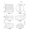
以下、本発明を実施するための最良の形態を、各実施例として示す図面と共に説明する。図1および図2は、本発明の実施例1の全熱交換素子である。図3ないし図5は、実施例2の全熱交換素子である。図6および図7は、実施例3の全熱交換器である。図8は、実施例1ないし3を含む本発明の各実施例の一部断面図であり、図8(a)は実施例1及び2について、(b)は実施例3について、(c)ないし(f)はそれぞれ実施例4ないし7について、全熱交換膜1の配設形態を示す。
Hereinafter, the best mode for carrying out the present invention will be described with reference to the drawings showing the embodiments. 1 and 2 show the total heat exchange element according to the first embodiment of the present invention. 3 to 5 show the total heat exchange element of the second embodiment. 6 and 7 show the total heat exchanger according to the third embodiment. 8 is a partial cross-sectional view of each embodiment of the present
以下のいずれの実施例においても、本発明の全熱交換素子は、全熱交換膜1で区切られた第一流路21及び第二流路22にそれぞれ第一及び第二の空気a1、a2を流通させて2種の空気の全熱交換を行なうものである。
そして、前記全熱交換膜1は、一端から他端まで連なる折曲又は湾曲部1Bを有すると共に、前記第一流路21及び第二流路22は、この折曲又は湾曲部1Bの連なる方向に沿って、第一及び第二それぞれの空気を流通させるものである。
In any of the following embodiments, the total heat exchange element of the present invention supplies the first and second air a1 and a2 to the
The total
また、本発明の全熱交換器は、全熱交換膜1で区切られた第一流路21及び第二流路22にそれぞれ第一及び第二の空気a1、a2を流通させて2種の空気の全熱交換を行なう全熱交換素子を具備する。すなわち、全熱交換膜1と、この全熱交換膜1の一面を側面の一部として第一の空気a1を流通させる第一流路21と、全熱交換膜1の他面を側面の一部として第二の空気a2を流通させる第二流路22と、を具備してなる。
Further, the total heat exchanger of the present invention distributes the first and second air a1 and a2 through the
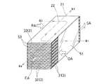
実施例1の全熱交換素子について、図1に斜視概観図を、図2にこれを製造する際の斜視分解説明図を、それぞれ示す。また、図8(a)に断面視における全熱交換膜の配置の概念図を示す。 About the total heat exchange element of Example 1, a perspective overview is shown in FIG. 1, and the perspective exploded explanatory drawing at the time of manufacturing this in FIG. 2 is shown, respectively. FIG. 8A shows a conceptual diagram of the arrangement of the total heat exchange membrane in a sectional view.
(全熱交換膜1)
全熱交換膜1は、通気性を有さないものであり、それ自体の表面及び裏面を流通する2種の空気の全熱(潜熱及び顕熱)交換を行うものである。全熱交換膜1は、それ(全熱交換膜1)自体の一端から他端まで連なるような、折曲又は湾曲部1Bを複数有する。この複数の折曲又は湾曲部1Bのうち、少なくとも一の折曲又は湾曲部1Bは、他のいずれかの折曲又は湾曲部1Bと反対側へ曲がってなる。
(Total heat exchange membrane 1)
The total
実施例1では、一枚の全熱交換膜1を連続的に折曲することで、山方向及び谷方向へ交互に曲げて折り込み、複数の前記折曲又は湾曲部1Bが、同一パターンで連続的に繰り返して形成される。具体的には、互いに略平行な複数の平面を等間隔毎に連ねて、左右対称の断面視略コ字型のパターンを交互に繰り返し形成したものである(図8(a))。特に、全熱交換素子の全体形状の全幅まで広がり、全体形状の端部である側面封止板51で折り曲げることで、構造的強度に優れた複数の平面を形成している。この複数の平面により、極辺に沿って伸びる多数層が積層形成される。各層間(それぞれの熱交換膜間)は交互に、室外空気と室内空気を流通させる第一流路21、第二流路22となる。
In Example 1, the whole
(全熱交換膜1の材質)
実施例1の全熱交換膜1は、親水性有機高分子膜を、全熱交換を行なう合成樹脂として定着してなる。全熱交換を行なう合成樹脂は、具体的には、下記一般式〔化1〕に示す三元共重合体の親水性スルフォン化ポリマーの構造を有するものである。
(Material of total heat exchange membrane 1)
The total
この三元共重合体の親水性スルフォン化ポリマーは、具体的には50〜30重量%のオレフィンモノマーたるエチレンと、50〜70重量%のアリルビニルモノマーたるスチレンとを有してなるエチレン・スチレン・ランダム共重合体を主成分とする。そして、前記親水性スルフォン化ポリマーからなる電解質膜は、高透湿性であって潜熱交換効率が高いものであり、全熱交換効率が高いものである。すなわち、本発明の前記電解質膜はそのミクロ構造の親水性イオンチャンネル内の水分拡散によ従来には無い非常に高い高透湿性(約75%の熱交換効率)を有するものである。 Specifically, the hydrophilic sulfonated polymer of this terpolymer is ethylene / styrene comprising 50 to 30% by weight of ethylene as an olefin monomer and 50 to 70% by weight of styrene as an allyl vinyl monomer.・ The main component is a random copolymer. The electrolyte membrane made of the hydrophilic sulfonated polymer has high moisture permeability, high latent heat exchange efficiency, and high total heat exchange efficiency. That is, the electrolyte membrane of the present invention has a very high moisture permeability (heat exchange efficiency of about 75%) that has not existed conventionally due to moisture diffusion in the hydrophilic ion channel of the microstructure.
(折曲又は湾曲部1B)
本発明の全熱交換膜1は、長手或いは短手方向に連なる折曲又は湾曲部1Bを、それ(全熱交換膜1)自体の一端から他端に亘って有する。折曲又は湾曲部1Bは、例えば図8の各図で示すように、断面視にていずれかの位置で、周囲と比して急激な曲率変化及び一定以上の曲率を有する曲部(ベンド部)をいう。このような図8の各図で示される曲部(ベンド部)が、その曲率を一定以上に維持したまま、全熱交換膜1の一端から他端にまで連なってなる。例えば、図8のうち(a)(b)(d)(e)の各図に示すような折曲部は、折り曲げによる折曲辺(へり部分)が全熱交換膜1の一端から他端にまで線状に伸びてなる。一方、図8のうち(c)(f)の各図に示すような湾曲部は、湾曲面が全熱交換膜1の一端から他端にまで連なる。
(Bent or
The total
実施例1においては、山方向及び谷方向へ交互に折曲してなり、図8(a)に示すように、一断面において、複数の前記折曲又は湾曲部1Bが同一パターンで連続的に繰り返す。折り曲げによる複数の折曲辺は、互いに交差することなく長手方向へ略直線状に伸びる。さらには、それぞれの折曲辺が互いに略並行である。また全熱交換膜1の一端から他端にかけて、その曲率すなわち折曲角度は略90度のまま一定に保持される。
In Example 1, it is alternately bent in the mountain direction and the valley direction, and as shown in FIG. 8 (a), a plurality of the bent or
(スペーサー3)
スペーサー3は、山方向及び谷方向へ連続的に折り込まれてなる各層の全熱交換膜1間に挟まれるように、複数が固定される。各層間の高さを確保するものである。熱交換膜の並設間隔は、1.5ないし2.0mm、さらには1.7mm程度であることが、優れた全熱交換効率及び低圧力損失のために好ましい。
(Spacer 3)
A plurality of
実施例1のそれぞれのスペーサー3は、一定の波形を連続的に有して広がる薄板からなる。この波形は並行して全熱交換素子の長手方向に伸びる。折り込まれて平行面を連続的に形成する全熱交換膜1間を、複数本の線状で固定することによって、全熱交換素子の形状を保持するものである。また同時に、空気の流通方向を誘導(ガイド)するものである。
Each
実施例1のスペーサー3の波形は、平面視にて全熱交換素子の長手方向に沿い、その両端で平面視同一方向に折曲するように伸びる。この波形形状は、両端の2箇所で折曲する。特に本実施例では折曲角度が略90度であり略コ字の流路を確保する。波形の形状は、ひとつおきの層において略同一であり、また、熱交換膜間の隣り合う各層において、それぞれ折曲方向が左右対称となる形状である。これにより、第一の空気a1と第二の空気a2とが、平面視矩形の全熱交換素子において、斜め向かいの位置で対向する方向に流入し、全熱交換素子内で互いに対向した後、流入位置と対称した斜め向かいの位置で流出する。流路の両端を除く中央部においては、第一の空気a1と第二の空気a2との流入方向が対向して交差する。この熱交換空気同士の交差角度は最大の180度とし、熱交換効率に優れたものとしている。
The waveform of the
(第一流路21及び第二流路22)
第一流路21は第一の空気a1を、第二流路22は第二の空気a2を、それぞれ流通させるものである。また第一流路21及び第二流路22は、共に全熱交換膜1の折曲又は湾曲部1Bの連なる長手方向に沿って、空気を流通させる。第一及び第二流路21、22の断面形状は、長手方向の任意断面において互いに同一又は略相似形状である。さらには、長手方向のいずれの位置においても略同一の断面形状である。
それぞれの折曲又は湾曲部1Bは、第一流路21及び第二流路22において、断面視上下左右のうちいずれか3方向に亘る側面を形成してなる。
(
The
Each of the bent or
(製造方法の例)
上記構成の全熱交換素子は、例えば、以下のように製造することによって得られる。
(Example of manufacturing method)
The total heat exchange element having the above configuration can be obtained, for example, by manufacturing as follows.
先ず、全熱交換膜1を一定の矩形形状にカットすることなく、幅のみを揃えた全熱交換膜1を、長尺のまま連続的に折り込んで、直方体の積層体を形成する。具体的には、山方向及び谷方向へ交互に、それぞれコ字断面となるように2箇所ずつ連続的に折曲する(図2)。この2箇所の折曲又は湾曲部1Bは、いずれの層においても等しい所定の縦距間隔を空けてなる。尚、隣り合って並設される熱交換膜の縦距間隔は、本実施例では1.7mm程度である。
First, without cutting the total
この折曲による積層の際、折り込んでなる各層間にスペーサー3を挟み込んで固定する(図2)。このとき、第一流路21、第二流路22それぞれのスペーサー3を、折り込み方向に合わせて交互に設ける。なお、全熱交換膜1の積層の形態を別途固定すれば、スペーサー3を全熱交換膜1の各層に接着固定する必要のないものとなる。
At the time of lamination by this bending, the
次に、折り込んで形成された直方体の積層体の両側面及び両端面に封止材5を貼着し、周囲を閉じた第一流路21及び第二流路22を形成する。
Next, the sealing material 5 is affixed on both side surfaces and both end surfaces of the cuboid laminated body formed by folding, and the
封止材5は、直方体の積層体の両側面のうち、長手方向両端を除いた中央部分に貼付する側面封止板51と、直方体の積層体の両端面とに貼付する(図2)端面封止板52とからなる。板状の封止材5を貼付することにより、第一及び第二流路21、22の左右いずれかの外側面を容易かつ嵩張ることなく形成する。
The sealing material 5 is attached to the
側面封止板51は、積層体よりも長手方向に短いものであり、両端を空けて積層体の側面に貼付する。積層体の側面のうち開けた両端の部分が、一系統(第一a1或いは第二a2のいずれか)の空気の流入、流出口を構成する。
The
(実施例1の効果)
実施例1では、第一流路21及び第二流路22の互いの断面形状は一断面内において略同一であるため、2種の空気それぞれの流れの状態(流量および流速)が類似する。また、第一流路21及び第二流路22の断面形状は共に、長手方向において略同一であるため、対向速度も長手方向で略均一となる。よって、2種の空気間で均等に、安定した全熱交換効率を得ることができる。
(Effect of Example 1)
In Example 1, since the cross-sectional shapes of the
また、実施例1では、複数の折曲又は湾曲部1が、互いに交差することなく長手方向へ略直線状に伸びてなるので、折曲又は湾曲部1Bの間を流通する2種の空気が整流となり、長手方向のいずれの断面においても略均一の高い相対速度で対向する。よって、圧力損失を小さなものとしながら、対向流による優れた熱交換効率を確保することができる。
Moreover, in Example 1, since the some bending or
さらに、実施例1では、一枚の全熱交換膜1を山方向及び谷方向へ交互に曲げることで積層形成してなるため、コンパクトな形態の積層体内に、多くの熱交換面積を確保することができる。
Furthermore, in Example 1, since one sheet of the total
また、実施例1のように連続的に折曲することで、比較的長尺の一体的な全熱交換膜1から全熱交換素子を形成することができる。これは、複数枚の全熱交換膜1を積層して形成する従来の全熱交換素子と比して、定形大へのカット工程や複数枚の積層工程等が不要である。
Further, by continuously bending as in the first embodiment, a total heat exchange element can be formed from a relatively long integral total
また、本実施例では、流路が90度で曲がるため、折り込みによる直方体の積層体が完成した後に端部封止板52を貼り付けることが可能となる。従来の積層してなる熱交換素子のように、各層間の封止のためリブ等の封止材を予め接着しておく必要は無い。よって、製造工程が簡略化し、より生産性に優れたものとなる。
Further, in this embodiment, since the flow path bends at 90 degrees, the
その他、各部の具体的な構成及び製造方法に関する具体的な工程は、上述した実施例に限定されるものでなく、本発明の趣旨を逸脱しない範囲で種々の変形が可能である。 In addition, the specific steps relating to the specific configuration and manufacturing method of each part are not limited to the above-described embodiments, and various modifications can be made without departing from the spirit of the present invention.
実施例2の全熱交換素子について、図3に斜視概観図を、図4に斜視分解説明図を、図5に流出入部の斜視拡大図を、それぞれ示す。また、断面視における全熱交換膜の配置の概念図は、実施例1と同様に図8(a)で示される。 About the total heat exchange element of Example 2, FIG. 3 shows a perspective overview, FIG. 4 shows a perspective exploded view, and FIG. 5 shows a perspective enlarged view of the inflow / outflow part. Moreover, the conceptual diagram of the arrangement of the total heat exchange membrane in a cross-sectional view is shown in FIG.
実施例2では、第一流路21及び第二流路22が、平面視にて左右対象のL字状となっている。各流路21、22は流入時にのみ平面視垂直に曲がって全熱交換膜1の側面を通り、その方向のまま全熱交換素子から流出する。流路の曲がりが交流箇所だけであるため、上記実施例1よりも圧力損失を抑えたものとなる。
In Example 2, the
また、いずれかの流路(例えば21)は、他の流路(例えば22)との交流箇所において平面視垂直に曲がる。この曲がりにより、交流箇所で流路内に乱流が発生し、第一又は第二の空気(a1又はa2)が満遍なく全熱交換膜1に接触することで、各流路21、22内での全熱交換効率の斑を抑えることができる。
In addition, any one of the flow paths (for example, 21) bends vertically in a plan view at an AC location with another flow path (for example, 22). Due to this bend, turbulent flow is generated in the flow path at the AC location, and the first or second air (a1 or a2) is uniformly contacted with the total
(実施例2の製造方法)
本実施例では、折り込む前段階で、全熱交換膜1の両端に、封止材5たるビード53を、全熱交換膜1の一方向へ厚みを有するように固着する。また、この全熱交換膜1と隣り合う上下層の全熱交換膜1には、それぞれ逆方向へ厚みを有するビード53を両端部の辺に亘って固着してなる(図5)。ビード53の厚みは、各層の縦距、すなわち並行する全熱交換膜1の隣り合う間隔の半分である。
(Production method of Example 2)
In the present embodiment, before the folding, the
これにより、折り込みによる直方体の積層体は、各層がひとつおきに向かい合うビード53によって閉ざされ、残りの各層が開放する。よって、直方体の積層体の一端部において、第一流路21又は第二流路22のいずれか一方(例えば第一流路21)のみが開放した流出口となる。また、直方体の積層体の他端部において他方(例えば第二流路22)のみが開放した流出口となる。
Thereby, the rectangular parallelepiped laminated body is closed by the
本発明のビード53とは、常温にて硬質又は中硬質固化する線状の樹脂材をいう。例えば、常温を超えた融点で粘性溶融する熱溶融樹脂が挙げられる。熱溶融樹脂は、溶融時に全熱交換膜1に塗布することで、接着剤を用いることなく容易に固着することができる。また接着剤を用いることなく固着することで、全熱交換素子の製造工程が簡易になり生産効率に優れたものとなる。接着剤を用いることなく固着することで、全熱交換素子の使用時に、接着剤に基づく有害ガスの発生や換気空気内への混入を防止することができる。
The
また熱溶融樹脂は常温にて弾性を有するため、風量の変化等による全熱交換素子の変形にも対応することができるものとなる。
実施例2の第一流路21、第二流路22により、圧力損失の小さいものとなり、送風機等の余分な動力を使うことなく、効率よく安価な換気運転が可能となる。
Further, since the hot-melt resin has elasticity at room temperature, it can cope with the deformation of the total heat exchange element due to the change in the air volume.
The
実施例2では端部封止板53は用いない。その他の構成は、実施例1と同様である。
In the second embodiment, the
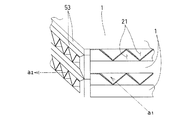
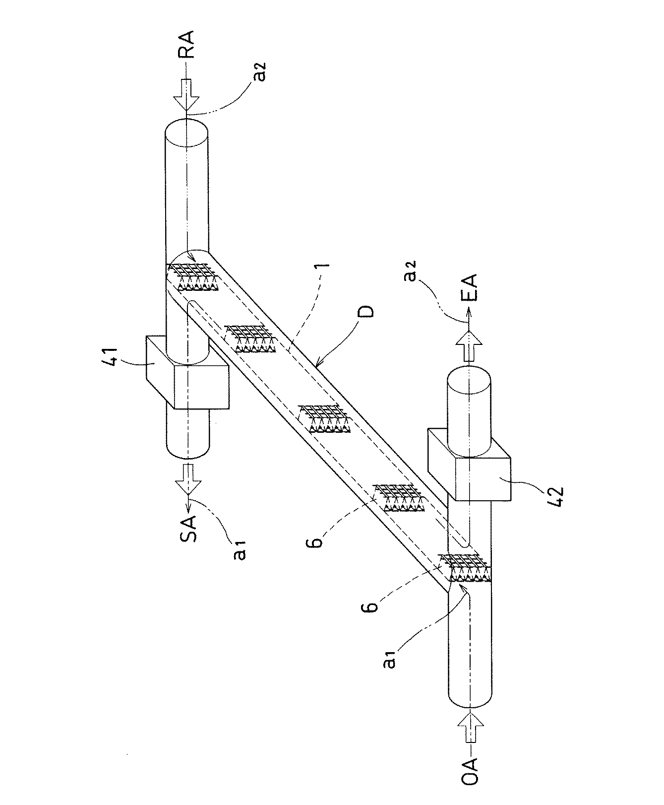
実施例3の全熱交換素子について、図6に斜視概観図を、図7に全熱交換膜1の部分拡大説明図を、それぞれ示す。
About the total heat exchange element of Example 3, a perspective-view schematic diagram is shown in FIG. 6, and the partial expanded explanatory view of the total
実施例3の全熱交換膜1は、山方向及び谷方向へ交互に折曲した波形として、一体的に形成したダクト形状Dの内部に、ダクト形状Dの断面を等面積で区切るように固定される。
The total
この固定は、固定部材6によって、折曲又は湾曲部1Bの両側面から、全熱交換膜1を固定するものである。固定部材6は、一対の網目状の硬質材からなり、上下端がダクト形状Dの内側面に固定される。この固定部材6はまた、長手方向に沿って全熱交換膜1の折曲又は湾曲部1Bを接着固定することで、流路2内の風圧に対して膜形状を保持する(図7)。
In this fixing, the total
ダクト形状Dの両端はT字管によって二又となり、それぞれが外気(OA)ダクト、排気(EA)ダクト、還気(RA)ダクト、給気(SA)ダクトへ接続される。このうち給気(SA)ダクトには、第一空気たる室外空気を運搬する第一送風機を介設し、排気(EA)ダクトには、第二空気たる室内空気を運搬する第二送風機を介設してなる。すなわち、実施例3の全熱交換器は、熱交換機能を果たす熱交換素子部が独立形状であり、送風機と分離してなる。 Both ends of the duct shape D are bifurcated by a T-tube, and each is connected to an outside air (OA) duct, an exhaust (EA) duct, a return air (RA) duct, and an air supply (SA) duct. Among them, the supply air (SA) duct is provided with a first blower for carrying outdoor air as the first air, and the exhaust (EA) duct is provided with a second blower for carrying indoor air as the second air. Set up. That is, the total heat exchanger of Example 3 has a heat exchange element portion that performs a heat exchange function and has an independent shape, and is separated from the blower.
実施例3におけるダクト形状Dは、図6に示すように略直管円形のスパイラルダクトであるが、フレキシブルダクトやベンド管、或いは方形断面の角ダクト等、任意の形状でよい。 The duct shape D in the third embodiment is a substantially straight circular spiral duct as shown in FIG. 6, but may be an arbitrary shape such as a flexible duct, a bend pipe, or a square duct having a square cross section.
(送風機)
本発明の実施例3における第一送風機及び第二送風機は、第一及び第二の2種の空気a1、a2を互いに対向する方向、すなわち正反対の方向に流通させるものである。2種の空気の交流角度は最大値たる180度である。2種の空気は、それぞれの流路の側方において、互いに対向しながら全熱交換膜1を介して接触する。
(Blower)
In the third embodiment of the present invention, the first blower and the second blower circulate the first and second types of air a1 and a2 in directions opposite to each other, that is, in opposite directions. The AC angle of the two kinds of air is 180 degrees which is the maximum value. The two types of air contact each other through the total
実施例3は、ダクト形状Dを含むダクト、及び送風機という簡易な外形の構成からなる。すなわち、実施例3では、ダクト形状Dの内部で全熱交換機能を有するものとし、送風機とは別体としてダクト連結されてなるため、省スペース内に設置できるコンパクトな形態となっている。 The third embodiment has a simple outer configuration such as a duct including a duct shape D and a blower. That is, in Example 3, since it has a total heat exchange function inside the duct shape D and is duct-connected as a separate body from the blower, it has a compact form that can be installed in a space-saving manner.
スパイラルダクト形状は、例えば径100mm、長さ3mの既存のダクトを使用し、この内部に幅430mm相当の全熱交換膜1を長手方向3mmに亘って固定することで、風量24CMH(0.4m3/min)程度の全熱交換を行なうことができる。既存のダクトを使用し、これに全熱交換膜1を固定してなることで、極めて安価な全熱交換器を得ることができる。
For example, an existing duct having a diameter of 100 mm and a length of 3 m is used as the spiral duct shape, and the total
その他の構成は、実施例1と同様である。 Other configurations are the same as those of the first embodiment.
このようにして得られた全熱交換素子は、一般的に4本のダクトにつながるチャンバー、或いはダクト内に装備される。4本のダクトは、それぞれ室外からの吸気(OA)、室内への供給気(SA)、及び、室内からの還気(RA)、室内への排気(EA)からなる。このチャンバー内又はチャンバー外に備えられた送風機により2種の空気を流通させ、第一種換気を行なうことができる。また、全熱交換器は、限られた設置スペースにおいて、好適に設置される。居住室の設備スペース内の他、種々の装置或いは機構内に収納して換気及び熱交換を行うことができる。 The total heat exchange element thus obtained is generally installed in a chamber or duct connected to four ducts. The four ducts are composed of outdoor intake air (OA), indoor supply air (SA), indoor return air (RA), and indoor exhaust air (EA). Two types of air can be circulated by a blower provided inside or outside the chamber to perform first type ventilation. Further, the total heat exchanger is preferably installed in a limited installation space. Ventilation and heat exchange can be performed by housing in various devices or mechanisms in addition to the equipment space of the living room.
1 全熱交換膜
1B 折曲又は湾曲部
21 第一流路
22 第二流路
a1 第一の空気
a2 第二の空気
D ダクト形状
1 Total
Claims (6)
The total heat exchange membrane 1 has a plurality of the bent or curved portions 1B, and at least one of the bent or curved portions 1B is bent to the opposite side of any other bent or curved portion 1B. The total heat exchanger according to 4 or 5.
Priority Applications (1)
| Application Number | Priority Date | Filing Date | Title |
|---|---|---|---|
| JP2004106788A JP2005291618A (en) | 2004-03-31 | 2004-03-31 | Total enthalpy heat exchange element and total enthalpy heat exchanger |
Applications Claiming Priority (1)
| Application Number | Priority Date | Filing Date | Title |
|---|---|---|---|
| JP2004106788A JP2005291618A (en) | 2004-03-31 | 2004-03-31 | Total enthalpy heat exchange element and total enthalpy heat exchanger |
Publications (1)
| Publication Number | Publication Date |
|---|---|
| JP2005291618A true JP2005291618A (en) | 2005-10-20 |
Family
ID=35324740
Family Applications (1)
| Application Number | Title | Priority Date | Filing Date |
|---|---|---|---|
| JP2004106788A Pending JP2005291618A (en) | 2004-03-31 | 2004-03-31 | Total enthalpy heat exchange element and total enthalpy heat exchanger |
Country Status (1)
| Country | Link |
|---|---|
| JP (1) | JP2005291618A (en) |
Cited By (8)
| Publication number | Priority date | Publication date | Assignee | Title |
|---|---|---|---|---|
| WO2010120122A3 (en) * | 2009-04-14 | 2011-01-20 | Lee Chan Bong | Electric heating device having curved air path and air exchange system using the same |
| WO2012056506A1 (en) * | 2010-10-25 | 2012-05-03 | 三菱電機株式会社 | Total heat exchange element and total heat exchanger |
| KR101401443B1 (en) * | 2012-05-29 | 2014-05-30 | (주)센도리 | Counterflow type heat exchanger |
| JP2014173786A (en) * | 2013-03-08 | 2014-09-22 | Techno Frontier:Kk | Heat exchanging element |
| KR20200145117A (en) * | 2019-06-20 | 2020-12-30 | 박준국 | Heat exchange apparatus for ventilating |
| KR20220008091A (en) * | 2020-07-13 | 2022-01-20 | 송길섭 | Counter flow total heat exchanger device using formability paper |
| CN116672906A (en) * | 2023-06-19 | 2023-09-01 | 绍兴百立盛新材料科技有限公司 | Preparation method of washable total heat exchange fresh air film |
| CN119756009A (en) * | 2025-02-07 | 2025-04-04 | 浙江万享科技股份有限公司 | A high efficiency open cooling tower |
-
2004
- 2004-03-31 JP JP2004106788A patent/JP2005291618A/en active Pending
Cited By (13)
| Publication number | Priority date | Publication date | Assignee | Title |
|---|---|---|---|---|
| WO2010120122A3 (en) * | 2009-04-14 | 2011-01-20 | Lee Chan Bong | Electric heating device having curved air path and air exchange system using the same |
| KR101192927B1 (en) | 2009-04-14 | 2012-10-18 | 이찬봉 | Heat exchanger with curved air course and air conditioning apparatus using the same |
| WO2012056506A1 (en) * | 2010-10-25 | 2012-05-03 | 三菱電機株式会社 | Total heat exchange element and total heat exchanger |
| JPWO2012056506A1 (en) * | 2010-10-25 | 2014-02-24 | 三菱電機株式会社 | Total heat exchange element and total heat exchanger |
| KR101401443B1 (en) * | 2012-05-29 | 2014-05-30 | (주)센도리 | Counterflow type heat exchanger |
| JP2014173786A (en) * | 2013-03-08 | 2014-09-22 | Techno Frontier:Kk | Heat exchanging element |
| KR20200145117A (en) * | 2019-06-20 | 2020-12-30 | 박준국 | Heat exchange apparatus for ventilating |
| KR102248936B1 (en) * | 2019-06-20 | 2021-05-06 | 박준국 | Heat exchange apparatus for ventilating |
| KR20220008091A (en) * | 2020-07-13 | 2022-01-20 | 송길섭 | Counter flow total heat exchanger device using formability paper |
| KR102356119B1 (en) * | 2020-07-13 | 2022-02-07 | 송길섭 | Counter flow total heat exchanger device using formability paper |
| CN116672906A (en) * | 2023-06-19 | 2023-09-01 | 绍兴百立盛新材料科技有限公司 | Preparation method of washable total heat exchange fresh air film |
| CN116672906B (en) * | 2023-06-19 | 2024-07-26 | 绍兴百立盛新材料科技有限公司 | Preparation method of washable total heat exchange fresh air film |
| CN119756009A (en) * | 2025-02-07 | 2025-04-04 | 浙江万享科技股份有限公司 | A high efficiency open cooling tower |
Similar Documents
| Publication | Publication Date | Title |
|---|---|---|
| EP3421921B1 (en) | Membrane support assembly for an energy exchanger | |
| TWI525294B (en) | Heat exchange components and air conditioning devices | |
| US20110209858A1 (en) | Indirect Evaporative Cooling Apparatus | |
| TWI421460B (en) | Heat exchange element | |
| CN101266109A (en) | Total heat exchanger and manufacturing method thereof | |
| JPH09184692A (en) | Heat exchanging element | |
| CN102414534A (en) | Total heat exchange element | |
| JP2004003838A (en) | Heat exchanger | |
| JP2005291618A (en) | Total enthalpy heat exchange element and total enthalpy heat exchanger | |
| CN115698618B (en) | Method for manufacturing countercurrent total heat exchanger | |
| JP4928295B2 (en) | Sensible heat exchange element | |
| JP2006250372A (en) | Total heat exchanger | |
| KR100911776B1 (en) | Manufacturing method of total heat exchanger and total heat exchanger | |
| KR101443053B1 (en) | Sensible heat exchanger | |
| KR20100059140A (en) | Heat exchange element for ventilating duct | |
| JP2006097958A (en) | Heat exchanger | |
| JP2006071149A (en) | Heat exchanging element | |
| JP2006071150A (en) | Heat exchanging element | |
| JP4021048B2 (en) | Heat exchange element | |
| KR101589488B1 (en) | Heat exchange structure | |
| JP7126617B2 (en) | Heat exchange element and heat exchange ventilator | |
| JPH11254047A (en) | Bending method for thin sheet used in heat exchanger and heat exchanger | |
| KR20260001936A (en) | total heat exchanger | |
| JPH02217789A (en) | Heat exchanging element and heat exchanger | |
| EP1136781A1 (en) | Air-to-air heat-exchange element |