JP2005291547A - Ventilator - Google Patents
Ventilator Download PDFInfo
- Publication number
- JP2005291547A JP2005291547A JP2004103677A JP2004103677A JP2005291547A JP 2005291547 A JP2005291547 A JP 2005291547A JP 2004103677 A JP2004103677 A JP 2004103677A JP 2004103677 A JP2004103677 A JP 2004103677A JP 2005291547 A JP2005291547 A JP 2005291547A
- Authority
- JP
- Japan
- Prior art keywords
- exhaust pipe
- mounting plate
- opening
- hood body
- fixed
- Prior art date
- Legal status (The legal status is an assumption and is not a legal conclusion. Google has not performed a legal analysis and makes no representation as to the accuracy of the status listed.)
- Granted
Links
- 230000002093 peripheral effect Effects 0.000 claims abstract description 26
- 210000000078 claw Anatomy 0.000 claims abstract description 20
- 238000009423 ventilation Methods 0.000 description 4
- XLYOFNOQVPJJNP-UHFFFAOYSA-N water Substances O XLYOFNOQVPJJNP-UHFFFAOYSA-N 0.000 description 4
- 238000010276 construction Methods 0.000 description 3
- 238000009434 installation Methods 0.000 description 2
- 238000005452 bending Methods 0.000 description 1
- 230000015572 biosynthetic process Effects 0.000 description 1
- 230000000694 effects Effects 0.000 description 1
- 238000005516 engineering process Methods 0.000 description 1
- 239000000463 material Substances 0.000 description 1
- 230000000149 penetrating effect Effects 0.000 description 1
Images
Landscapes
- Ventilation (AREA)
Abstract
Description
本発明は、換気装置に関するもので、特に外壁を貫通する排気管とフード体との取付け構造に関するものである。 The present invention relates to a ventilation device, and more particularly, to an attachment structure for an exhaust pipe penetrating an outer wall and a hood body.
従来、屋内と屋外とを外壁を隔して連通する排気管にフード体を連結する手段としては、例えば、特許第3135208号や特開2000−120938、同2002−81708、同2002−130757、同2003−202143、同2004−12086などの技術が知られているが、排気管には外径寸法の異なるものが数種類ある(現在のJISでは、VP管100×114mm/VU管107×114mm/SU管100×106mmがある。)ことから、この排気管への嵌挿取付けを確実に行うためには、取付口の口径寸法の異なる複数のフード体を用意するか又は両者の取付けを補助するための継手などを用意しておかなければならない手数がかかっていた。 Conventionally, as means for connecting a hood body to an exhaust pipe that communicates indoors and outdoors with an outer wall separated, for example, Japanese Patent No. 3135208, Japanese Patent Laid-Open No. 2000-120938, Japanese Patent Laid-Open No. 2002-81708, Japanese Patent Laid-Open No. 2002-130757, Although technologies such as 2003-202143 and 2004-12086 are known, there are several types of exhaust pipes having different outer diameters (in the current JIS, VP pipe 100 × 114 mm / VU pipe 107 × 114 mm / SU Therefore, in order to securely insert and attach the exhaust pipe to the exhaust pipe, in order to prepare a plurality of hood bodies having different caliber sizes of the attachment ports or to assist the attachment of both. It took a lot of time to prepare the joints.
しかし、これでは材料コストが高くつき、排気管へのフード体の施工工事が経済性を欠くものとして課題となっていた。 However, this increases the material cost, and the construction work of the hood body on the exhaust pipe has been a problem because it lacks economic efficiency.
そこで、本発明は、前記のように外径寸法の異なる排気管に、フード体を即応して取付け施工をすることができる構造を、フード体側の開口部に設けておくことによって前記した従来の欠点を除去し、経済性の高い換気装置を提供することを目的とするものである。 Therefore, the present invention provides a structure in which the hood body can be quickly attached to the exhaust pipes having different outer diameters as described above by providing the opening on the hood body side as described above. An object of the present invention is to provide a highly economical ventilation device that eliminates the drawbacks.
本発明は、フード体の周縁段部に囲まれて形成した開口部に取付板を固着し、この取付板には排気管を嵌挿する開口部において外側方向又は内側方向に曲折する鍔縁部を形成し、前記開口部に適当間隔をおいて外側斜め方向に発条爪を突設し、この発条爪によって前記開口部に嵌挿した排気管の外周面部に食い込むように固定する。 The present invention fixes a mounting plate to an opening formed by being surrounded by a peripheral step of the hood body, and the mounting plate is bent to the outer side or the inner side at the opening into which the exhaust pipe is inserted. And a protruding claw projecting in an obliquely outward direction at an appropriate interval from the opening, and fixed so as to bite into the outer peripheral surface portion of the exhaust pipe fitted into the opening by the protruding claw.
前記開口部においては、外側又は内側方向に鍔縁部を形成せず、直接適当間隔をおいて発条爪を外側斜め方向に突設してもよい。 In the opening portion, the ridged claw may be provided in an obliquely outward direction at an appropriate interval without forming the heel edge portion in the outward or inward direction.
また、前記フード体の周縁段部と同高に成る凸起部を取付板の適当位置に設けるとよい。 Moreover, it is good to provide the protrusion part which becomes the same height as the peripheral step part of the said hood body in the suitable position of a mounting plate.
本発明のフード体の取付板の開口部は前記のような特殊な構造に成るものであるから、排気管の外径寸法が異なるものであっても、施工者は予め外壁に設置してある排気管に屋外方向からフード体をその取付板の開口部を嵌挿すれば、嵌挿後は開口部周縁の発条爪がその弾発力によって自在に即応して排気管の外径周面部に食い込むように当接して固着することになるから、工事現場における換気装置の取付け施工を円滑かつ確実に行うことができるようになり、しかも嵌着した後はフード体の固定の弛緩や落下などの現象は起ることはないから安全である。 Since the opening of the mounting plate of the hood body of the present invention has a special structure as described above, even if the outer diameter of the exhaust pipe is different, the installer is installed on the outer wall in advance. If the hood body is inserted into the exhaust pipe from the outdoor direction and the opening of the mounting plate is inserted, the ridge claw at the periphery of the opening will immediately respond to the outer peripheral surface of the exhaust pipe by its elastic force. Since it will come into contact and stick so that it bites in, the ventilation equipment can be installed smoothly and reliably at the construction site, and after fitting, the hood body can be fixed loosely or dropped, etc. The phenomenon is safe because it never happens.
また、排気管を屋内から屋外にかけて外壁内で傾斜をつけて施工する場合に起る取付板開口部と排気管との間の間隙部分を、開口部周囲の発条爪の弾発力によって十分補って確実に塞いで固定することができるようになる。 In addition, the gap between the mounting plate opening and the exhaust pipe that occurs when the exhaust pipe is installed with an inclination in the outer wall from indoor to outdoor is sufficiently compensated by the elastic force of the claw around the opening. Can be securely plugged and fixed.
このようなフード体の取付板の構造によって、排気管を取付ける換気装置の設置コストを大きく低減することができ、経済的効果も大きい。 By such a structure of the mounting plate of the hood body, the installation cost of the ventilation device for attaching the exhaust pipe can be greatly reduced, and the economic effect is also great.
また、フード体の取付板は、その周囲の周縁段部及び平ら面の適当位置に複数の凸起部を設けて外壁面に密接することによって、フード体全体を安定状態を保持して固定できるようになる。 In addition, the mounting plate of the hood body can be fixed while maintaining the stable state of the hood body by providing a plurality of protruding portions at appropriate positions on the peripheral stepped portion and the flat surface of the hood body and closely contacting the outer wall surface. It becomes like this.
フード体の取付板の開口部に屋内から外壁を通って嵌挿した排気管は、その管の外径に即応して開口部周囲を発条爪が自在に弾発当接して外周面に食い込むように固定することになるから、たとえ排気管の外径寸法が異なるものであったとしても、その取付け施工を確実に行うことができるようになる。 The exhaust pipe fitted through the outer wall from the indoor to the opening of the mounting plate of the hood body responds to the outer diameter of the pipe so that the flaring claw can freely spring around and bite into the outer peripheral surface. Therefore, even if the outer diameter of the exhaust pipe is different, the installation work can be performed reliably.
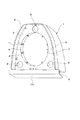
1は任意形状に成るフード体で、このフード体の周縁部の内側方向には段部2を曲折形成する。 Reference numeral 1 denotes a hood body having an arbitrary shape, and a stepped portion 2 is bent in the inner direction of the peripheral edge of the hood body.
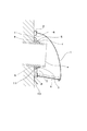
3は前記フード体1の周縁段部2に囲まれて形成した開口に固着した取付板で、この取付板には排気管aが嵌挿する口径を有する開口部4を設ける。
この開口部4においては、前記取付板3の外側のフード体1方向に曲折する鍔縁部5を形成し、開口部4の内側周縁部は角面のない円弧面6に成る。
In the
前記鍔縁部5は、取付板開口部4の内側の排気管a方向に曲折して形成してもよい。
The
7・・は前記開口部4の鍔縁部5に適当間隔をおいて斜め外側方向に切込み突設した発条爪で、この発条爪は開口部4に嵌挿される排気管aの外径寸法が異なっても、その外周面に弾発力を発揮して当接するようになるとともに停止した位置で排気管の外周面部に食い込むようにして固定する。
7 ··· is a protruding claw projecting obliquely outward at an appropriate interval from the
また、開口部4の鍔縁部5が内側方向に形成しているものにあっては、発条爪7・・は開口部4から直接外側斜め方向に突設するように成る。
Further, in the case where the
さらに、開口部4においては、外側又は内側方向への鍔縁部の形成をなくし、外側斜め方向に突設する発条爪7・・の設置だけにしてもよい。
Further, in the
8・は前記取付板3の平ら面の適当位置に前記フード体周縁段部2と同高にして設けた凸起部で、この凸起部及び前記周縁段部2とは外壁面に当接するように成る。
8 is a protruding portion provided at an appropriate position on the flat surface of the
9は前記フード体1の開口底面部に設けた格子状の水滴落下板で、これは開閉し得るように成るもので、排気管aの内周底面部に蓄まったゴミや油脂などの除去のためには、この水滴落下板を開口して指先を入れるようにする。 9 is a lattice-shaped water drop dropping plate provided on the bottom of the opening of the hood body 1, which can be opened and closed, and removes dirt, oil and fat accumulated on the inner peripheral bottom of the exhaust pipe a. For this purpose, the water drop drop plate is opened and the fingertip is inserted.
10は前記取付板3の下端辺部に前記水滴落下板8方向に設けた任意形状の流水板である。
11は嵌挿した排気管aとフード体取付板3の開口部の内周縁との間にできた間隙部分を完全に埋めるコーキング部である。
1 フード体
2 周縁段部
3 取付板
4 開口部
5 鍔縁部
6 円弧面
7・・ 発条爪
8・ 凸起部
DESCRIPTION OF SYMBOLS 1 Hood body 2
Claims (4)
The ventilator according to claim 1, 2, or 3, wherein a protruding portion is provided at an appropriate position of the mounting plate so as to have the same height as the peripheral step portion of the hood body.
Priority Applications (1)
| Application Number | Priority Date | Filing Date | Title |
|---|---|---|---|
| JP2004103677A JP4763971B2 (en) | 2004-03-09 | 2004-03-31 | Air vent |
Applications Claiming Priority (3)
| Application Number | Priority Date | Filing Date | Title |
|---|---|---|---|
| JP2004065213 | 2004-03-09 | ||
| JP2004065213 | 2004-03-09 | ||
| JP2004103677A JP4763971B2 (en) | 2004-03-09 | 2004-03-31 | Air vent |
Publications (3)
| Publication Number | Publication Date |
|---|---|
| JP2005291547A true JP2005291547A (en) | 2005-10-20 |
| JP2005291547A6 JP2005291547A6 (en) | 2006-01-26 |
| JP4763971B2 JP4763971B2 (en) | 2011-08-31 |
Family
ID=35324675
Family Applications (1)
| Application Number | Title | Priority Date | Filing Date |
|---|---|---|---|
| JP2004103677A Expired - Fee Related JP4763971B2 (en) | 2004-03-09 | 2004-03-31 | Air vent |
Country Status (1)
| Country | Link |
|---|---|
| JP (1) | JP4763971B2 (en) |
Citations (4)
| Publication number | Priority date | Publication date | Assignee | Title |
|---|---|---|---|---|
| JPS5881291A (en) * | 1981-11-05 | 1983-05-16 | 昭和電工株式会社 | Stud for outer layer pipe |
| JPS58164862A (en) * | 1982-03-24 | 1983-09-29 | 今井 一吉 | Floor sleeve installating method and floor sleeve |
| JP2004012086A (en) * | 2002-06-11 | 2004-01-15 | Bakuma Kogyo Kk | Ventilation structure |
| JP2004045010A (en) * | 2002-05-24 | 2004-02-12 | Kishimoto Seikei Kk | Connecting structure of ventilator |
-
2004
- 2004-03-31 JP JP2004103677A patent/JP4763971B2/en not_active Expired - Fee Related
Patent Citations (4)
| Publication number | Priority date | Publication date | Assignee | Title |
|---|---|---|---|---|
| JPS5881291A (en) * | 1981-11-05 | 1983-05-16 | 昭和電工株式会社 | Stud for outer layer pipe |
| JPS58164862A (en) * | 1982-03-24 | 1983-09-29 | 今井 一吉 | Floor sleeve installating method and floor sleeve |
| JP2004045010A (en) * | 2002-05-24 | 2004-02-12 | Kishimoto Seikei Kk | Connecting structure of ventilator |
| JP2004012086A (en) * | 2002-06-11 | 2004-01-15 | Bakuma Kogyo Kk | Ventilation structure |
Also Published As
| Publication number | Publication date |
|---|---|
| JP4763971B2 (en) | 2011-08-31 |
Similar Documents
| Publication | Publication Date | Title |
|---|---|---|
| KR102059569B1 (en) | Drain pipe connector and drain traps including same | |
| JP5257284B2 (en) | Ventilation hood | |
| JP3917145B2 (en) | Oblique hanging bolt mounting device | |
| KR20180124444A (en) | A connector for electric conduit | |
| JP2010032084A (en) | Outer wall terminal ventilation opening | |
| JP2009287854A (en) | Air conditioner | |
| JP2005291547A (en) | Ventilator | |
| JP2005291547A6 (en) | Ventilation equipment | |
| JP5075529B2 (en) | Protective cover for cable | |
| JP2017211038A (en) | Connection structure of duct for piping to building | |
| JP5315841B2 (en) | Bathroom ventilation dryer | |
| JP2009207220A (en) | Cable-mounting fixture | |
| JP3815377B2 (en) | Equipment fall prevention bracket | |
| US6007422A (en) | Universal damper mounting system and method | |
| WO2023055809A1 (en) | Side wall seal for piping | |
| JP2005232872A (en) | Louver installing structure | |
| JP5695443B2 (en) | Wiring retractor for rooftop equipment | |
| JP4822372B2 (en) | Water shield for conshielded sprinkler head | |
| KR200303213Y1 (en) | Connecting and fixing device for the form and coverlet comprising cable tray or duct | |
| CN212299207U (en) | An air conditioner outdoor unit | |
| JP4871117B2 (en) | sleeve | |
| JP2003161483A (en) | Apparatus for preventing slobbering | |
| JP3359886B2 (en) | Air vent | |
| KR0123668Y1 (en) | Electric pole cover to prevent building a nest | |
| JP3403134B2 (en) | Mounting structure of ventilation equipment |
Legal Events
| Date | Code | Title | Description |
|---|---|---|---|
| A621 | Written request for application examination |
Free format text: JAPANESE INTERMEDIATE CODE: A621 Effective date: 20070216 |
|
| A977 | Report on retrieval |
Free format text: JAPANESE INTERMEDIATE CODE: A971007 Effective date: 20090910 |
|
| A131 | Notification of reasons for refusal |
Free format text: JAPANESE INTERMEDIATE CODE: A131 Effective date: 20090915 |
|
| A521 | Request for written amendment filed |
Free format text: JAPANESE INTERMEDIATE CODE: A523 Effective date: 20091113 |
|
| A02 | Decision of refusal |
Free format text: JAPANESE INTERMEDIATE CODE: A02 Effective date: 20100226 |
|
| A521 | Request for written amendment filed |
Free format text: JAPANESE INTERMEDIATE CODE: A523 Effective date: 20100520 |
|
| A911 | Transfer to examiner for re-examination before appeal (zenchi) |
Free format text: JAPANESE INTERMEDIATE CODE: A911 Effective date: 20100603 |
|
| A912 | Re-examination (zenchi) completed and case transferred to appeal board |
Free format text: JAPANESE INTERMEDIATE CODE: A912 Effective date: 20100730 |
|
| A521 | Request for written amendment filed |
Free format text: JAPANESE INTERMEDIATE CODE: A523 Effective date: 20110414 |
|
| A61 | First payment of annual fees (during grant procedure) |
Free format text: JAPANESE INTERMEDIATE CODE: A61 Effective date: 20110610 |
|
| FPAY | Renewal fee payment (event date is renewal date of database) |
Free format text: PAYMENT UNTIL: 20140617 Year of fee payment: 3 |
|
| R150 | Certificate of patent or registration of utility model |
Ref document number: 4763971 Country of ref document: JP Free format text: JAPANESE INTERMEDIATE CODE: R150 Free format text: JAPANESE INTERMEDIATE CODE: R150 |
|
| R250 | Receipt of annual fees |
Free format text: JAPANESE INTERMEDIATE CODE: R250 |
|
| R250 | Receipt of annual fees |
Free format text: JAPANESE INTERMEDIATE CODE: R250 |
|
| R250 | Receipt of annual fees |
Free format text: JAPANESE INTERMEDIATE CODE: R250 |
|
| R250 | Receipt of annual fees |
Free format text: JAPANESE INTERMEDIATE CODE: R250 |
|
| R250 | Receipt of annual fees |
Free format text: JAPANESE INTERMEDIATE CODE: R250 |
|
| R250 | Receipt of annual fees |
Free format text: JAPANESE INTERMEDIATE CODE: R250 |
|
| R250 | Receipt of annual fees |
Free format text: JAPANESE INTERMEDIATE CODE: R250 |
|
| R250 | Receipt of annual fees |
Free format text: JAPANESE INTERMEDIATE CODE: R250 |
|
| R250 | Receipt of annual fees |
Free format text: JAPANESE INTERMEDIATE CODE: R250 |
|
| LAPS | Cancellation because of no payment of annual fees |