JP2005291531A - Biomass fuel combustion method and apparatus - Google Patents
Biomass fuel combustion method and apparatus Download PDFInfo
- Publication number
- JP2005291531A JP2005291531A JP2004103209A JP2004103209A JP2005291531A JP 2005291531 A JP2005291531 A JP 2005291531A JP 2004103209 A JP2004103209 A JP 2004103209A JP 2004103209 A JP2004103209 A JP 2004103209A JP 2005291531 A JP2005291531 A JP 2005291531A
- Authority
- JP
- Japan
- Prior art keywords
- biomass fuel
- furnace
- coal
- fuel
- supplied
- Prior art date
- Legal status (The legal status is an assumption and is not a legal conclusion. Google has not performed a legal analysis and makes no representation as to the accuracy of the status listed.)
- Granted
Links
Images

Classifications
-
- Y—GENERAL TAGGING OF NEW TECHNOLOGICAL DEVELOPMENTS; GENERAL TAGGING OF CROSS-SECTIONAL TECHNOLOGIES SPANNING OVER SEVERAL SECTIONS OF THE IPC; TECHNICAL SUBJECTS COVERED BY FORMER USPC CROSS-REFERENCE ART COLLECTIONS [XRACs] AND DIGESTS
- Y02—TECHNOLOGIES OR APPLICATIONS FOR MITIGATION OR ADAPTATION AGAINST CLIMATE CHANGE
- Y02E—REDUCTION OF GREENHOUSE GAS [GHG] EMISSIONS, RELATED TO ENERGY GENERATION, TRANSMISSION OR DISTRIBUTION
- Y02E50/00—Technologies for the production of fuel of non-fossil origin
- Y02E50/10—Biofuels, e.g. bio-diesel
-
- Y—GENERAL TAGGING OF NEW TECHNOLOGICAL DEVELOPMENTS; GENERAL TAGGING OF CROSS-SECTIONAL TECHNOLOGIES SPANNING OVER SEVERAL SECTIONS OF THE IPC; TECHNICAL SUBJECTS COVERED BY FORMER USPC CROSS-REFERENCE ART COLLECTIONS [XRACs] AND DIGESTS
- Y02—TECHNOLOGIES OR APPLICATIONS FOR MITIGATION OR ADAPTATION AGAINST CLIMATE CHANGE
- Y02E—REDUCTION OF GREENHOUSE GAS [GHG] EMISSIONS, RELATED TO ENERGY GENERATION, TRANSMISSION OR DISTRIBUTION
- Y02E50/00—Technologies for the production of fuel of non-fossil origin
- Y02E50/30—Fuel from waste, e.g. synthetic alcohol or diesel
-
- Y—GENERAL TAGGING OF NEW TECHNOLOGICAL DEVELOPMENTS; GENERAL TAGGING OF CROSS-SECTIONAL TECHNOLOGIES SPANNING OVER SEVERAL SECTIONS OF THE IPC; TECHNICAL SUBJECTS COVERED BY FORMER USPC CROSS-REFERENCE ART COLLECTIONS [XRACs] AND DIGESTS
- Y02—TECHNOLOGIES OR APPLICATIONS FOR MITIGATION OR ADAPTATION AGAINST CLIMATE CHANGE
- Y02W—CLIMATE CHANGE MITIGATION TECHNOLOGIES RELATED TO WASTEWATER TREATMENT OR WASTE MANAGEMENT
- Y02W10/00—Technologies for wastewater treatment
- Y02W10/40—Valorisation of by-products of wastewater, sewage or sludge processing
-
- Y—GENERAL TAGGING OF NEW TECHNOLOGICAL DEVELOPMENTS; GENERAL TAGGING OF CROSS-SECTIONAL TECHNOLOGIES SPANNING OVER SEVERAL SECTIONS OF THE IPC; TECHNICAL SUBJECTS COVERED BY FORMER USPC CROSS-REFERENCE ART COLLECTIONS [XRACs] AND DIGESTS
- Y02—TECHNOLOGIES OR APPLICATIONS FOR MITIGATION OR ADAPTATION AGAINST CLIMATE CHANGE
- Y02W—CLIMATE CHANGE MITIGATION TECHNOLOGIES RELATED TO WASTEWATER TREATMENT OR WASTE MANAGEMENT
- Y02W30/00—Technologies for solid waste management
- Y02W30/50—Reuse, recycling or recovery technologies
- Y02W30/78—Recycling of wood or furniture waste
Landscapes
- Furnace Details (AREA)
- Combustion Of Fluid Fuel (AREA)
- Gasification And Melting Of Waste (AREA)
- Processing Of Solid Wastes (AREA)
- Treatment Of Sludge (AREA)
- Solid Fuels And Fuel-Associated Substances (AREA)
Abstract
【課題】粉砕動力を抑えて効率的に木質系バイオマス燃料を燃焼系に供給して燃焼させる燃焼方法と燃焼装置を提供すること。
【解決手段】新たに外部から受け入れたバイオマス燃料に対して一サイクルの粉砕工程でバイオマス燃料の全量を浮遊燃焼可能な微粒になるまで粉砕するのではなく、一部は投入した後に浮遊燃焼可能な微粒とし、残りは粗粒として浮遊燃焼できずにボイラ下部へ落下させ、落下したものは回収して再粉砕する石炭焚きボイラシステムとすることで、回収した粗粒バイオマス燃料はある程度炭化しており、新たに受け入れたバイオマス燃料に比べて低い粉砕動力で粉砕できることから、全体的に粉砕動力を押さえることが可能となる。
【選択図】図1Disclosed is a combustion method and a combustion apparatus for efficiently supplying woody biomass fuel to a combustion system while suppressing pulverization power.
SOLUTION: The biomass fuel newly received from the outside is not pulverized until it becomes fine particles capable of floating combustion in one cycle of the pulverization process, but a part of the biomass fuel can be floated after being charged. The remaining coarse biomass fuel is carbonized to some extent by using a coal fired boiler system that makes fine particles and the rest as coarse particles that cannot be suspended and burned and falls to the bottom of the boiler. Since pulverization can be performed with a lower pulverization power than newly accepted biomass fuel, the overall pulverization power can be reduced.
[Selection] Figure 1
Description
本発明は石炭焚きボイラなどの燃焼装置において、石炭とバイオマス燃料を混焼させる場合において、バイオマス燃料を経済的に粉砕して高効率に燃焼させるのに好適なバイオマス燃料の粉砕及び燃焼技術に関するものである。 TECHNICAL FIELD The present invention relates to a biomass fuel pulverization and combustion technique suitable for economically pulverizing biomass fuel and burning it with high efficiency in the case of co-firing coal and biomass fuel in a combustion apparatus such as a coal-fired boiler. is there.
本発明でいうバイオマス燃料とは化石燃料以外の植物系燃料であり、その種類を特定のものに限定するものではないが、特に森林や生活リサイクルとして出てくる全ての廃材や汚泥、さらにその二次加工製品等を含む燃料となりうる発熱量を有する植物系燃料をいうものとする。 Biomass fuel as used in the present invention is a plant-based fuel other than fossil fuels, and the type thereof is not limited to a specific one. It shall mean a plant-based fuel having a calorific value that can be a fuel containing a next processed product.
従来バイオマス燃料の燃焼には、ストーカ炉や流動床式の燃焼炉が主に使用されてきた。この場合には、バイオマス燃料の乾燥は行われずに、そのまま火炉へ供給する方式が採用されていた。事前にバイオマス燃料の乾燥を行わずに火炉へ供給し燃焼させた場合に、バイオマス燃料中に含まれる水分による顕熱と潜熱分のエネルギーロスにより燃焼効率が悪化する。しかし、これらの火炉の燃焼効率は通常でも20%から30%程度と低く、水分の火炉内への持ち込みによる燃焼効率の低下は無視できる範囲であった。 Conventionally, a stoker furnace or a fluidized bed type combustion furnace has been mainly used for combustion of biomass fuel. In this case, a method of supplying biomass fuel as it is without drying biomass fuel has been adopted. When biomass fuel is supplied to a furnace without being dried in advance and burned, the combustion efficiency deteriorates due to sensible heat due to moisture contained in the biomass fuel and energy loss due to latent heat. However, the combustion efficiency of these furnaces is usually as low as about 20% to 30%, and the reduction in combustion efficiency due to the introduction of moisture into the furnace was negligible.
近年、バイオマス燃料を再生可能なエネルギとして、率先的に使用する動きが活発化してきた。特に発電目的のボイラではバイオマス燃料を燃焼させる場合には燃焼効率を高効率に維持して発電することが必須の条件となる。 In recent years, the use of biomass fuel as renewable energy has been actively promoted. In particular, in a boiler for power generation, when burning biomass fuel, it is an indispensable condition to generate power while maintaining high combustion efficiency.
石炭を微粉砕した後に燃焼用空気と共に火炉内に供給して燃焼させるバーナを設けた発電目的のコンベンショナルな石炭焚きボイラ火炉において、バイオマス燃料を副燃料として火炉に供給して燃焼させる場合、バイオマス燃料を細かく粉砕して、気流にのせてボイラ火炉へ供給する方法が考えられる。 In a conventional coal-fired boiler furnace with a burner that is provided with a burner that is supplied to the furnace with combustion air after being pulverized and burned, biomass fuel is supplied to the furnace as a secondary fuel and burned. It is conceivable to finely pulverize and supply to a boiler furnace in an air stream.
まず、図4に主に発電用に使用される従来の微粉炭焚きボイラの系統図を示す。ボイラ火炉1には火炉1の高さ方向に複数段と幅方向に複数台のバーナ4がそれぞれ火炉1の対向する位置の壁面に設けられており、バーナ4の下流側にはバーナ4と同様に火炉1の対向する位置の壁面に空気噴出口OFA(Over Firing Airport)2が設けられている。
First, FIG. 4 shows a system diagram of a conventional pulverized coal fired boiler mainly used for power generation. In the
図4に示すように前記バーナ4へは各バーナ段に対応する石炭微粉砕機(ミル)6が設けられており、運炭設備10から燃料バンカ9に一旦貯蔵された石炭を複数の定量供給装置8から切り出して各ミル6に供給している。通常、ミル6は各バーナ段の対向する壁面にあるバーナ段(図4ではバーナ4と記載されている。)毎に微粉炭を供給するように構成されており、図4に示す場合は三段のバーナ4が対向する火炉壁面に配置されているので、6台のミル構成となっている。さらにミル6とバーナ4の運用ではミル6およびバーナ4の点検と部品交換におけるローテーションを考えて、システムが構築されており、ミル6の一台は停止させていても、負荷100%の運転ができるように設定されている。
As shown in FIG. 4, the
前記したように燃料の石炭は屋内または屋外の石炭のストックヤードから運炭設備10、例えばベルトコンベアにより燃料バンカ9へ送り込まれ、燃料バンカ9の下部に設けられた定量供給装置8で計量されて前記ベルトコンベアなどの上に切り出された後、停止中のミル6を除いて各ミル6に送り込まれ、微粉砕されてバーナ4まで気流搬送され、図示していない燃焼用空気と共に火炉内へ供給されて燃焼される。
As described above, the fuel coal is fed from the indoor or outdoor coal stock yard to the
前記燃焼用空気は図示していない押込み通風気FDF(Force Draft Fan)によって加圧された後、図示していないエアヒータ(熱交換器)により、約350℃まで昇温された後、各バーナ段に対応して設けられた燃焼用空気用の風箱3に供給されて各バーナ段毎の複数台のバーナ4へ分配される。その後、前記燃焼用空気は高効率燃焼に必要な速度と旋回強度を与えられ、火炉1内に面したバーナスロートから、火炉1内へ噴出供給され微粉炭燃料と混合して燃焼させる。
バイオマス燃料を火力発電用の石炭焚きボイラ用の副燃料として使用する場合、特に既設の石炭焚きボイラにおいて混焼(Co-Firing)する場合、発電効率の低下を可能な限り抑制しなければならない。 When biomass fuel is used as an auxiliary fuel for a coal-fired boiler for thermal power generation, especially when co-firing in an existing coal-fired boiler, reduction in power generation efficiency must be suppressed as much as possible.
特に木質系のバイオマス燃料を副燃料として石炭焚きボイラ用に使用する場合に発電効率が低下する原因は主に2つある。1つは木質系バイオマス燃料に含まれる水分であり、もう1つは、木質系バイオマス燃料を粉砕する動力の問題である。前者の問題を解決するには、木質系バイオマス燃料の前処理として乾燥工程が不可欠となる。後者の粉砕動力の問題に関しては、木質系バイオマス燃料の粉砕粒度を1mmアンダーとした場合、粉砕の動力原単位は100〜200kW/tとなり、石炭焚きボイラで石炭の粉砕に使用される石炭粉砕機と比較して10倍以上の粉砕動力が必要となる。 In particular, when woody biomass fuel is used as a secondary fuel for a coal-fired boiler, there are mainly two causes for the reduction in power generation efficiency. One is moisture contained in the woody biomass fuel, and the other is a problem of power for crushing the woody biomass fuel. In order to solve the former problem, a drying process is indispensable as a pretreatment of the woody biomass fuel. Regarding the problem of the latter pulverization power, when the pulverization particle size of the woody biomass fuel is under 1 mm, the pulverization power basic unit is 100 to 200 kW / t, and the coal pulverizer used for pulverizing coal with a coal-fired boiler Compared to the above, a grinding power of 10 times or more is required.
現状では、できるだけ粉砕動力を抑えて効率的に木質系バイオマス燃料を石炭焚きボイラ火炉へ供給することが求められている。従来の石炭焚きボイラへ木質系バイオマス燃料を供給する場合には、木質系バイオマス燃料を浮遊燃焼できる状態であることが必須となる。浮遊燃焼可能か否かは主に木質系バイオマス燃料の粒子径に依存する。具体的には5mm以下まで粉砕することが必要である。 At present, it is required to efficiently supply woody biomass fuel to a coal-fired boiler furnace while suppressing the pulverization power as much as possible. When supplying woody biomass fuel to a conventional coal-fired boiler, it is essential that the woody biomass fuel be in a state where it can be floated and burned. Whether floating combustion is possible depends mainly on the particle size of the woody biomass fuel. Specifically, it is necessary to grind to 5 mm or less.
木質系バイオマス燃料の粉砕装置は大きく2種類ある。まず、ハンマーミルと呼ばれる衝撃粉砕を主体とした粉砕機である。次にカッターミルと呼ばれる刃物を使用した粉砕機である。しかしながらいずれの粉砕機においても、木質系バイオマス燃料の粉砕に必要な動力が石炭用粉砕機と比較して10倍以上大きく、既設石炭焚きボイラに木質系バイオマス燃料の粉砕供給システムを追設して、石炭と混焼するシステムを構築する場合には、補機動力が増加することから発電効率の低下が予測される。 There are two main types of wood biomass fuel crushers. First, it is a pulverizer called impact hammering called hammer mill. A crusher using a cutter called a cutter mill. However, in any of the pulverizers, the power required for pulverizing the woody biomass fuel is more than 10 times larger than that of the coal pulverizer, and a woody biomass fuel pulverization supply system has been added to the existing coal-fired boiler. When building a system that co-fires with coal, power generation efficiency is expected to decrease because auxiliary power increases.
例えば1000MWの発電能力がある石炭焚きボイラにおいて、石炭燃料の供給量は、炭種にもよるが約350t/hであり、これに木質系バイオマス燃料を発熱量ベースで10%混焼する場合、木質系バイオマス燃料は発熱量が石炭の約50%であることから約70t/hの供給量が必要となる。
石炭微粉砕機の場合、粉砕動力原単位が約20kWh/tなので約350t/h×20kWh/t=7000kWの動力が必要となる。
For example, in a coal-fired boiler having a power generation capacity of 1000 MW, the supply amount of coal fuel is about 350 t / h, although it depends on the type of coal. When wood-based biomass fuel is mixed with 10% on a calorific value basis, Since the calorific value of the biomass fuel is about 50% of that of coal, a supply amount of about 70 t / h is required.
In the case of a coal pulverizer, since the pulverization power unit is about 20 kWh / t, a power of about 350 t / h × 20 kWh / t = 7000 kW is required.
一方、木質系バイオマス燃料の場合は、大目にみて約100kWh/tとすると、同じく約100kWh/t×70t/h=7000kWの動力が必要であり、石炭の供給量は10%カットとなるので、約315t/h×20kWh/t=6300kWとなる。石炭のみの場合には約7000kW、石炭と木質系バイオマス燃料の場合は、約6300+7000=13300kWであるので、約2倍の粉砕動力となる。 On the other hand, in the case of woody biomass fuel, if it is roughly set to about 100 kWh / t, the power of about 100 kWh / t × 70 t / h = 7000 kW is required, and the supply amount of coal is cut by 10%. 315 t / h × 20 kWh / t = 6300 kW. In the case of only coal, it is about 7000 kW, and in the case of coal and woody biomass fuel, it is about 6300 + 7000 = 13300 kW.
既存の石炭焚きボイラの専焼システムに対して増分である約6300kW(=13300−7000kW)となる。これは、発電能力の約0.63%に相当するため、木質系バイオマス燃料により火炉内に持ち込まれる水分による効率の低下を含めると大きな低下となる。 It is about 6300 kW (= 13300-7000 kW) which is an increment with respect to the exclusive combustion system of the existing coal fired boiler. Since this corresponds to about 0.63% of the power generation capacity, it is a large decrease when including a decrease in efficiency due to moisture brought into the furnace by the woody biomass fuel.
しかしながら現状のハンマーミルとカッターミルでは、粉砕動力を既存の石炭ミル並にするのは難しく、木質系バイオマス燃料を専用に低粉砕動力で粉砕できる微粉砕ミルの開発を待つか、または粗粒の木質系バイオマス燃料でも完全に燃焼できる燃焼システムを検討する等が必要になっていた。 However, with the current hammer mill and cutter mill, it is difficult to make the pulverization power comparable to that of the existing coal mill, and waiting for the development of a fine pulverization mill that can pulverize wood-based biomass fuel exclusively with low pulverization power, It has become necessary to study a combustion system that can completely burn even with woody biomass fuel.
本発明の課題は、粉砕動力を抑えて効率的に木質系バイオマス燃料を燃焼系に供給して燃焼させる燃焼方法と燃焼装置を提供することである。 An object of the present invention is to provide a combustion method and a combustion apparatus for efficiently supplying a woody biomass fuel to a combustion system while suppressing pulverization power and burning it.
請求項1記載の発明は、石炭を主燃料とし、バイオマス燃料を副燃料として燃焼用空気と共に火炉内に供給して燃焼させるバイオマス燃料の燃焼方法において、前記火炉内に供給したバイオマス燃料のうち火炉の下部に落下したものを回収して粉砕し前記火炉内に供給することを特徴とするバイオマス燃料の燃焼方法である。
The invention according to
請求項2記載の発明は、前記火炉内に供給したバイオマス燃料のうち火炉の下部に落下したものを回収して前記火炉内に供給する石炭と混合して粉砕し、得られた粉砕物を火炉に供給して燃焼させることを特徴とするバイオマス燃料の燃焼方法である。
Invention of
請求項3記載の発明は、前記火炉内に供給したバイオマス燃料のうち火炉の下部から回収したものを水分50%以下になるまで乾燥した後に、前記火炉内に供給する石炭と混合して粉砕し、得られた粉砕物を火炉に供給して燃焼させることを特徴とするバイオマス燃料の燃焼方法である。 The invention according to claim 3 is that the biomass fuel supplied from the lower part of the furnace supplied to the furnace is dried to a moisture content of 50% or less, then mixed with the coal supplied to the furnace and pulverized. The biomass fuel combustion method is characterized in that the obtained pulverized product is supplied to a furnace and burned.
請求項4記載の発明は、前記火炉内に供給したバイオマス燃料のうち火炉の下部から回収したものを水分50%以下になるまで乾燥した後に、石炭と混合することなく、新たに受け入れたバイオマス燃料と混合して粉砕し、得られた粉砕物を火炉に供給して燃焼させることを特徴とするバイオマス燃料の燃焼方法である。
The invention according to
請求項5記載の発明は、前記火炉の下部から回収したバイオマス燃料の炭化度が高い場合は石炭と混合して粉砕し、得られた粉砕物を火炉に供給して燃焼させ、前記火炉の下部から回収したバイオマス燃料の炭化度が低い場合はバイオマス燃料と混合して粉砕し、得られた粉砕物を火炉に供給して燃焼させることを特徴とするバイオマス燃料の燃焼方法である。 In the invention according to claim 5, when the biomass fuel recovered from the lower part of the furnace has a high carbonization degree, it is mixed with coal and pulverized, and the obtained pulverized product is supplied to the furnace and burned. When the biomass fuel recovered from the plant has a low carbonization degree, the biomass fuel is pulverized by mixing with the biomass fuel, and the pulverized product obtained is supplied to a furnace and combusted.
請求項6記載の発明は、石炭を主燃料とし、バイオマス燃料を副燃料とする火炉と、主燃料である石炭を粉砕する手段と、副燃料であるバイオマス燃料を粉砕する手段と、前記石炭粉砕手段で粉砕された石炭を火炉に供給する手段と、前記バイオマス燃料粉砕手段で粉砕されたバイオマス燃料を火炉に供給する手段と、前記バイオマス燃料を火炉に供給する手段から火炉に供給して火炉の下部に落下したものを回収する手段と、該回収手段で回収したものを前記石炭粉砕手段またはバイオマス燃料粉砕手段に供給する手段と、前記いずれかの粉砕手段で粉砕されたものを前記火炉内に再供給する手段とを備えたことを特徴とするバイオマス燃料の燃焼装置である。
The invention according to
請求項7記載の発明は、前記バイオマス燃料を火炉に供給する手段から火炉に供給されたバイオマス燃料のうち前記回収手段により回収されたものを受け入れる手段と、該受け入れ手段を介して石炭粉砕手段またはバイオマス燃料粉砕手段に供給する手段と、前記いずれかの粉砕手段で粉砕されたものを前記火炉内に再供給する手段とを備えたことを特徴とするバイオマス燃料の燃焼装置である。 The invention according to claim 7 is a means for receiving from the means for supplying the biomass fuel to the furnace a biomass fuel supplied to the furnace that has been recovered by the recovery means; a coal pulverizing means via the receiving means; A biomass fuel combustion apparatus comprising: means for supplying biomass fuel to the means for pulverizing; and means for supplying again the material pulverized by any one of the pulverizing means into the furnace.
請求項1、2、6記載の発明によれば、既設の石炭焚きボイラなどの燃焼装置にバイオマス燃料を副燃料として混焼する場合、バイオマス燃料の石炭との混合設備が必要なだけで、大掛かりな改造は必要としない経済的利点がある。このように、本発明はボイラなどの燃焼装置の改造が必要ないので、低コストでかつ効果的なバイオマス燃料燃焼システムを構築できるメリットがある。 According to the first, second, and sixth aspects of the present invention, when biomass fuel is co-fired as an auxiliary fuel in a combustion apparatus such as an existing coal-fired boiler, only a facility for mixing biomass fuel with coal is required, which is not large. There is an economic advantage that no modification is required. Thus, since the present invention does not require modification of a combustion apparatus such as a boiler, there is a merit that a low-cost and effective biomass fuel combustion system can be constructed.
石炭焚きボイラなどの燃焼装置の炉底には火炉内から落下してくるクリンカ、スラグ、アッシュ等を受ける湿式のホッパが設けられていることが多く、その場合には落下したバイオマス燃料も水没した後に回収されることになる。また、石炭焚きボイラなどの燃焼装置の炉底に乾式のホッパが設けられていることもあるが、その場合にはホッパへの落下物を外部に運び出すコンベア等の搬送装置の後流側に回収したバイオマス燃料以外のものを比重等を利用して分離する分離装置を設けることが必要となる。いずれにしても回収されたバイオマス燃料を再粉砕する過程で水没等により多量の水分を含有することになる。 Wet hoppers that receive clinker, slag, ash, etc. falling from the inside of the furnace are often provided at the bottom of combustion equipment such as coal-fired boilers. It will be collected later. In addition, a dry hopper may be provided at the bottom of a combustion device such as a coal-fired boiler, but in that case, it is collected on the downstream side of a transport device such as a conveyor that carries the fallen objects to the hopper to the outside. It is necessary to provide a separation device that separates materials other than the biomass fuel using specific gravity or the like. In any case, a large amount of water is contained due to submergence or the like in the process of regrinding the recovered biomass fuel.
請求項3、4記載の発明によれば、この炉底から回収したバイオマス燃料を水分50%以下になるまで乾燥させるので、回収したバイオマス燃料に含まれる水分が火炉内に持ち込まれることを防止することができる。 According to the third and fourth aspects of the present invention, the biomass fuel recovered from the furnace bottom is dried until the moisture becomes 50% or less, so that the moisture contained in the recovered biomass fuel is prevented from being brought into the furnace. be able to.
請求項5記載の発明によれば、火炉の下部から回収したバイオマス燃料は火炉内での燃焼により少なくとも一部が炭化しており、この炭化度が高い場合は炭化度が低いバイオマス燃料に比べて粉砕し易いので、石炭粉砕機に供給して石炭と前記回収したバイオマス燃料とを同時粉砕し、バイオマス燃料の炭化度が低い場合は炭化度が高いバイオマス燃料に比べて粉砕し難いので、新しく受け入れたバイオマス燃料とバイオマス燃料粉砕機に供給して新規のバイオマス燃料と前記回収したバイオマス燃料とを同時粉砕し、火炉に供給する。このように、回収したバイオマス燃料の炭化度に応じて、その粉砕機を切り替えて、能率的に燃焼させることができる。 According to the invention described in claim 5, the biomass fuel recovered from the lower part of the furnace is at least partially carbonized by combustion in the furnace, and when this carbonization degree is high, it is compared with biomass fuel having a low carbonization degree. Since it is easy to pulverize, it is supplied to a coal pulverizer to simultaneously pulverize the coal and the recovered biomass fuel. If the biomass fuel has a low carbonization degree, it is difficult to pulverize compared to a biomass fuel with a high carbonization degree. The new biomass fuel and the recovered biomass fuel are simultaneously pulverized by supplying to the biomass fuel and the biomass fuel pulverizer and supplied to the furnace. Thus, according to the carbonization degree of the collect | recovered biomass fuel, the crusher can be switched and it can burn efficiently.
請求項7記載の発明によれば、石炭焚きボイラなどの燃焼装置の炉底から回収したバイオマス燃料を石炭粉砕手段またはバイオマス粉砕手段で同時粉砕する際に、一旦受け入れ手段に供給した後に定量的に切り出して前記各粉砕手段に供給するので、安定した混焼割合の粉砕物を火炉に供給することができる。 According to the seventh aspect of the present invention, when biomass fuel recovered from the bottom of a combustion apparatus such as a coal-fired boiler is simultaneously pulverized by the coal pulverizing means or the biomass pulverizing means, the biomass fuel is once quantitatively supplied to the receiving means. Since it cuts and supplies to each said grinding | pulverization means, the pulverized material of the stable co-firing ratio can be supplied to a furnace.
以下、本発明の実施例について図面を用いて説明する。 Embodiments of the present invention will be described below with reference to the drawings.
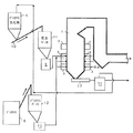
図1に本実施例のバイオマス燃焼技術を適用した石炭焚きボイラについて説明する。 図1に示す構成は、図4の石炭焚きボイラに本発明のバイオマス燃料の燃焼技術を適用した場合の実施例を説明するためのものである。図1では図4に示す装置と同一の装置については、一部の図示と説明を省略する。 FIG. 1 illustrates a coal fired boiler to which the biomass combustion technique of this embodiment is applied. The configuration shown in FIG. 1 is for explaining an embodiment in which the biomass fuel combustion technique of the present invention is applied to the coal-fired boiler of FIG. In FIG. 1, some illustrations and descriptions of the same devices as those shown in FIG. 4 are omitted.
木質系バイオマス燃料(以下、単にバイオマス燃料と称することもある)は水分含有量が50〜60%の状態でバイオマス燃料貯蔵ヤード16(例えば貯蔵用のサイロや山積み状に置かれる貯蔵パイル等の場合がある)に船もしくはトラックで輸送された後、一時保管される。石炭焚きボイラにおいてバイオマス燃料と石炭を混焼する場合には石炭焚きボイラの立地場所内のバイオマス燃料バンカ12に移送供給されてストックされる。
Woody biomass fuel (hereinafter sometimes simply referred to as biomass fuel) is a biomass
次に、バイオマス燃料用の破砕機13で石炭焚きボイラ火炉内で全量ではないが、投入した量の80%程度が浮遊燃焼可能な粒度、例えば5mm程度に粗粉砕された後、気流搬送により主燃料としての石炭が燃焼されている火炉1内へ供給されて燃焼される。火炉1内へ供給したバイオマス燃料の全量が浮遊燃焼可能になるように粉砕するときの粉砕動力は、前記したように80%程度が浮遊燃焼可能になるように粉砕するときの粉砕動力に比して指数関数的に増加することが知られているが、本実施例では指数関数的に増加する以前の粉砕動力で粉砕する。
Next, the
ここでは、バイオマス燃料の粒度は5mm程度としているが、バイオマス燃料の性状、ボイラ負荷や各段のバーナ5点火パターン等によりボイラ火炉1内の燃焼ガスの流動状態が異なるため一概には決められない。本実施例ではバイオマス燃料の投入量の80%程度が浮遊燃焼可能である程度の粉砕動力で粉砕したときのバイオマス燃料の粉砕の程度が5mmであった場合に対応する例である。その場合5mm以上のバイオマス燃料粒子は炉底へ落下する。前記したように石炭焚きボイラ炉底には火炉内から落下してくるクリンカ、スラグ、アッシュ等を受ける湿式のホッパまたは乾式のホッパが設けられている。本実施例の場合には火炉の炉底部には落下物を外部に搬出するコンベア17のみを図示している。該コンベア17は、いずれのホッパが設けられた場合にも前記ホッパの底部に設けられている。回収された粒子は比較的粗い粒子であり、部分的又は全量炭化しており、炉底に設けられたコンベア17によってボイラ外部へ搬出された後、湿式ホッパで液中に回収した場合の二次分離または乾式ホッパの場合には一次分離となる分離装置(湿式による比重分離装置)14によって分離される。
Here, the particle size of the biomass fuel is about 5 mm. However, the flow state of the combustion gas in the
前記分離後のバイオマス燃料粒子は受け入れホッパ15へ供給回収された後、火炉に供給する粉砕物を最終的に粉砕する粉砕装置の上流側に定量的に供給する。例えば石炭の運炭設備(ベルトコンベアなど)10内に一定の混合比率で切り出され、石炭焚きボイラの建屋に隣接して設けられた石炭バンカ11へ供給され、該石炭バンカ11の近傍、例えば直下部、に設けられた石炭微粉砕機6で粉砕されて図示していない通風機による気流搬送によりバーナ4へ供給燃焼される。
The separated biomass fuel particles are supplied and recovered to the receiving
石炭微粉砕機6では石炭と回収されたバイオマス燃料の炭化物が同時粉砕されることになるが、バイオマス燃料は少なくとも一部が炭化しており、石炭微粉砕機6で石炭を粉砕するときの通常の粉砕動力の範囲内で容易に粉砕される。
The coal pulverizer 6 simultaneously pulverizes the coal and the recovered biomass fuel carbide, but the biomass fuel is at least partially carbonized, and the
このように火炉1の炉底に落下したバイオマス燃料粒子を回収し、再粉砕して火炉1に再投入することを行えば過度な粉砕動力を用いることなく、経済性が高い高効率な石炭とバイオマス燃料との混焼が実現できる。
If the biomass fuel particles that have fallen to the furnace bottom of the
本実施例のバイオマス燃料の燃焼方法および装置を用いることにより、木質系のバイオマス燃料を高効率で燃焼させることができ、高度なサーマルリサイクルシステムを実現することができる。さらに通常の既設ボイラにおける燃焼時に発生するNOxを効果的に脱硝することもできる。 By using the biomass fuel combustion method and apparatus of the present embodiment, woody biomass fuel can be burned with high efficiency, and an advanced thermal recycling system can be realized. Furthermore, NOx generated during combustion in a normal existing boiler can be effectively denitrated.
本発明者らは、小型の石炭焚き火炉(微粉炭供給量:200kg/h)において、発熱量10%相当の木質系バイオマス燃料を微粉炭と同時燃焼した場合、微粉炭のみの燃焼に比べて約10%のNOx低減効果が得られ、木質系バイオマス燃料を混ぜることで脱硝効果が顕著になることを見出した。 In the small-sized coal-fired furnace (the supply amount of pulverized coal: 200 kg / h), the present inventors have compared the combustion of only pulverized coal when the woody biomass fuel corresponding to a calorific value of 10% is burned simultaneously with the pulverized coal. It was found that a NOx reduction effect of about 10% was obtained, and that the denitration effect became remarkable by mixing woody biomass fuel.
木質系バイオマス燃料の燃焼においてHCN、NH3、炭化水素等が発生し、これらの熱分解ガスにはNOに対する還元作用があり、NOがN2へ還元する。NOの生成還元反応は極めて複雑であるが、HCNとNH3の存在がNOの生成還元反応に大きく影響していることは良く知られている。酸素が残存する雰囲気ではHCN、NH3はNOへ転換することから、還元雰囲気でNOが存在することが必須条件となる。 In the combustion of the woody biomass fuel, HCN, NH 3 , hydrocarbons, etc. are generated, and these pyrolysis gases have a reducing action on NO, and NO is reduced to N 2 . Although the NO reduction reaction is extremely complicated, it is well known that the presence of HCN and NH 3 greatly affects the NO reduction reaction. Since HCN and NH 3 are converted to NO in an atmosphere in which oxygen remains, it is essential that NO exists in a reducing atmosphere.
木質系バイオマス燃料が、NO還元に有効である理由は次のように考えられる。木質系バイオマス燃料を分析すると、揮発分の比率が多く、着火性を表す燃料比(固定炭素/揮発分)が0.6程度と低く、石炭と比較してみれば褐炭に相当し、きわめて着火しやすい。揮発分が多いことは加熱により容易に可燃性ガスが気相へ放出することを意味している。 The reason why woody biomass fuel is effective for NO reduction is considered as follows. When analyzing woody biomass fuel, the ratio of volatile matter is large, and the fuel ratio (fixed carbon / volatile matter) indicating ignitability is as low as about 0.6. It's easy to do. A large amount of volatile matter means that the combustible gas is easily released into the gas phase by heating.
加熱されて熱分解した可燃性ガスの種類は加熱速度と加熱温度により異なるが、主にメタン(CH4)であり、1,000℃以上の高温で、かつ酸素が存在しない条件でNOを効果的に還元する。すなわち木質系のバイオマス燃料で還元炎を形成すれば、通常の微粉炭燃焼より低NOx燃焼が実現可能である。従って、バイオマス燃料を燃焼させる場合には空気比(バイオマス燃料の搬送用空気量にバイオマス燃料の燃焼用空気量を加えたものをバイオマス燃料を完全燃焼するための理論空気量で割った値)を低くして燃焼することにより、より大きな燃焼排ガスの低NOx化効果が得られる。 The type of combustible gas that is heated and pyrolyzed varies depending on the heating rate and heating temperature, but it is mainly methane (CH 4 ), which is effective at high temperatures of 1,000 ° C or higher and in the absence of oxygen. Reduced. That is, if a reducing flame is formed with woody biomass fuel, lower NOx combustion can be realized than ordinary pulverized coal combustion. Therefore, when burning biomass fuel, the air ratio (the value obtained by adding the amount of combustion air for biomass fuel to the amount of air for conveying biomass fuel divided by the amount of theoretical air for complete combustion of biomass fuel) By lowering and burning, the effect of lowering NOx of larger combustion exhaust gas can be obtained.
ここでHCN、NH3が不安定な物質であることから、NOとの混合は迅速でなければならない。もしも混合が遅れると脱硝効果が無くなることに加えて、二段燃焼用空気とこれら還元ガスが反応してNOになってしまう。従って木質系バイオマス燃料がNOの還元剤として有効に作用するためには火炉1内への投入位置は、火炎の内部が望ましい。
Here, since HCN and NH 3 are unstable substances, mixing with NO must be rapid. If mixing is delayed, the NOx removal effect is lost, and the two-stage combustion air reacts with the reducing gas to become NO. Therefore, in order for the woody biomass fuel to effectively act as a NO reducing agent, the charging position into the
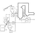
図2に示す本実施例は、図1の系統のうち、分離装置14と受け入れホッパ15間に、乾燥機18を取り付けた構造を備えている例である。
The present embodiment shown in FIG. 2 is an example in which a
図示していないが石炭焚きボイラの多くは炉底部に水を張った湿式の炉底ホッパ、すなわち火炉内からのスラグ等落下物の受け入れ装置が設けてあり、このため炉底に落下したバイオマス燃料も同じ受け入れ装置内に落下する。従って、回収したバイオマス燃料には水分が多く含まれるが、バイオマス燃料に含まれる水分が火炉内に持ち込まれることを防止するために乾燥機18を設ける。また水分が多いとバイオマス燃料が粉砕しにくくなる特性がある。
Although not shown, many coal-fired boilers are equipped with a wet bottom hopper with water on the bottom of the furnace, that is, a device for receiving fallen objects such as slag from the inside of the furnace. Falls into the same receiving device. Therefore, although the recovered biomass fuel contains a large amount of moisture, a
すなわち、ボイラ火炉1から回収したバイオマス燃料は全部又は部分的に炭化物となっているが、水分を多く含むと部分的に炭化したバイオマス燃料と炭化物との混合過程でバイオマス燃料の非炭化部分の水分が増加することによる。従って、乾燥機18を火炉1に供給する粉砕物を最終的に80%が浮遊燃焼できる程度に粉砕する粉砕装置の上流側に設けることで最適な粉砕動力での粉砕が可能となる。炉底から回収したバイオマス燃料を乾燥機18に導き、乾燥させた後に炭化物受け入れホッパ15へ回収し、石炭の運炭設備(ベルトコンベアなど)10内に一定の混合比率で切り出し、石炭焚きボイラの立地場所内に設けられた石炭バンカ11へ供給し、石炭微粉砕機6で粉砕して火炉内へ供給して燃焼させる。
In other words, the biomass fuel recovered from the
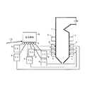
図3に示す本実施例は、図1の系統とは異なり、回収したバイオマス燃料をバイオマス燃料用の粉砕機13で同時粉砕し、さらに分離装置14から受け入れホッパ15間に乾燥機を取り付けたものである。
In the present embodiment shown in FIG. 3, unlike the system of FIG. 1, the recovered biomass fuel is simultaneously pulverized by a pulverizer 13 for biomass fuel, and a dryer is attached between the
図3に示す実施例は特にバイオマス燃料用微粉砕機13の粉砕動力を低く抑えた場合に炉底に落下し回収したバイオマス燃料を石炭微粉砕機6で同時粉砕しないケースである。同時粉砕する場合には回収したバイオマス燃料の粉砕性による粉砕動力の調整が必要となるが、本実施例の場合は回収したバイオマス燃料の炭化度が悪い場合に対応した例であり、新たに受け入れたバイオマス燃料の粉砕動力で粉砕することにより各粉砕機からの粉砕物の火炉への供給を安定化する。
The embodiment shown in FIG. 3 is a case where the biomass fuel dropped and recovered at the bottom of the furnace is not simultaneously pulverized by the
バイオマス燃料の炭化度の状態を見て、炭化度が良くないと、図3に示すように、再度バイオマス燃料用微粉砕機13の上流側に供給する経路からバイオ粉砕機13で粉砕して火炉に供給する。また、炭化度の程度が良いと図2のように石炭微粉砕機6の上流側に供給しても良い。また各粉砕機の上流側に個々に供給する以外に、各粉砕機に直接供給することも可能である。その場合には粉砕機内で始めて混合されることになるが、そのような構成とした場合には特に石炭と回収し定量的に切り出して混合した場合に、バイオマス燃料と石炭とが粉砕機に至る経路中で分離することにより混合率の変動を防止することが可能となる。
When the carbonization degree of the biomass fuel is observed, if the carbonization degree is not good, as shown in FIG. 3, it is pulverized by the bio pulverizer 13 again from the path supplied to the upstream side of the biomass fuel pulverizer 13 and the furnace. To supply. Further, when the degree of carbonization is good, it may be supplied to the upstream side of the
さらに図示していないが、炉底に落下し、回収したバイオマス燃料の炭化の程度に応じて図2に示す石炭バンカ11または図3に示すバイオバンカ12に炉底に落下し回収したバイオマス燃料の供給先を切り換えるシステムを設けることも可能である。
Furthermore, although not shown in figure, supply of the biomass fuel which fell to the furnace bottom and fell to the furnace bottom shown in FIG. 2 or the
本発明によればバイオマス燃料を副燃料として既設の石炭焚きボイラに適用でき、低コストでかつ効果的な木質系バイオマス燃料燃焼システムを構築できる。 According to the present invention, biomass fuel can be applied as an auxiliary fuel to an existing coal-fired boiler, and a low-cost and effective woody biomass fuel combustion system can be constructed.
1 火炉 2 空気噴出口
3 風箱 4 バーナ
5 バーナ 6 石炭微粉砕機
8 定量供給装置 9、11 石炭バンカ
10 運炭設備 12 バイオマスバンカ
13 バイオマス燃料粉砕機 14 分離装置
15 受け入れホッパ 16 バイオマス燃料貯蔵ヤード
17 コンベア 18 乾燥機
DESCRIPTION OF
Claims (7)
前記火炉内に供給したバイオマス燃料のうち、火炉の下部に落下したものを回収して粉砕し、前記火炉内に供給することを特徴とするバイオマス燃料の燃焼方法。 In the combustion method of biomass fuel, in which coal is the main fuel, biomass fuel is used as a secondary fuel, and the combustion air is supplied into the furnace and burned.
A biomass fuel combustion method characterized by collecting, pulverizing, and supplying the biomass fuel that has fallen to the lower part of the furnace among the biomass fuel supplied into the furnace.
主燃料である石炭を粉砕する手段と、
副燃料であるバイオマス燃料を粉砕する手段と、
前記石炭粉砕手段で粉砕された石炭を火炉に供給する手段と、
前記バイオマス燃料粉砕手段で粉砕されたバイオマス燃料を火炉に供給する手段と、
前記バイオマス燃料を火炉に供給する手段から火炉に供給して火炉の下部に落下したものを回収する手段と、
該回収手段で回収したものを前記石炭粉砕手段またはバイオマス燃料粉砕手段に供給する手段と、前記いずれかの粉砕手段で粉砕されたものを前記火炉内に再供給する手段とを備えたことを特徴とするバイオマス燃料の燃焼装置。 A furnace with coal as the main fuel and biomass fuel as an auxiliary fuel;
Means for pulverizing coal, the main fuel,
Means for pulverizing biomass fuel as a secondary fuel;
Means for supplying coal pulverized by the coal pulverizing means to a furnace;
Means for supplying biomass fuel pulverized by the biomass fuel pulverizing means to a furnace;
Means for supplying the biomass fuel to the furnace from the means for supplying to the furnace and recovering the one falling to the lower part of the furnace;
A means for supplying the coal recovered by the recovery means to the coal pulverizing means or the biomass fuel pulverizing means; and a means for re-supplying the pulverized one of the pulverizing means into the furnace. Biomass fuel combustion device.
Of the biomass fuel supplied to the furnace from the means for supplying the biomass fuel to the furnace, a means for receiving the biomass fuel recovered by the recovery means, and supplying the coal fuel to the biomass fuel pulverizing means or the biomass fuel pulverizing means via the receiving means 7. The biomass fuel combustion apparatus according to claim 6, further comprising: means; and means for re-feeding the pulverized product by any one of the pulverizing means into the furnace.
Priority Applications (1)
| Application Number | Priority Date | Filing Date | Title |
|---|---|---|---|
| JP2004103209A JP4367768B2 (en) | 2004-03-31 | 2004-03-31 | Biomass fuel combustion method and apparatus |
Applications Claiming Priority (1)
| Application Number | Priority Date | Filing Date | Title |
|---|---|---|---|
| JP2004103209A JP4367768B2 (en) | 2004-03-31 | 2004-03-31 | Biomass fuel combustion method and apparatus |
Publications (2)
| Publication Number | Publication Date |
|---|---|
| JP2005291531A true JP2005291531A (en) | 2005-10-20 |
| JP4367768B2 JP4367768B2 (en) | 2009-11-18 |
Family
ID=35324659
Family Applications (1)
| Application Number | Title | Priority Date | Filing Date |
|---|---|---|---|
| JP2004103209A Expired - Fee Related JP4367768B2 (en) | 2004-03-31 | 2004-03-31 | Biomass fuel combustion method and apparatus |
Country Status (1)
| Country | Link |
|---|---|
| JP (1) | JP4367768B2 (en) |
Cited By (15)
| Publication number | Priority date | Publication date | Assignee | Title |
|---|---|---|---|---|
| JP2008215710A (en) * | 2007-03-05 | 2008-09-18 | Tokyo Electric Power Co Inc:The | Solid biomass fuel supply system |
| CN100513869C (en) * | 2007-09-06 | 2009-07-15 | 中国科学技术大学 | Biomass high temperature combustion boiler |
| JP2009222265A (en) * | 2008-03-14 | 2009-10-01 | Ube Ind Ltd | Wood waste supplying method and device |
| WO2009139404A1 (en) | 2008-05-16 | 2009-11-19 | カワサキプラントシステムズ株式会社 | Biomass-mixed-firing pulverized coal fired boiler and operation method of the boiler |
| WO2011106550A3 (en) * | 2010-02-26 | 2011-12-22 | Global Greensteam Llc | Biomass-to-energy combustion method |
| JP2012093006A (en) * | 2010-10-25 | 2012-05-17 | Chugoku Electric Power Co Inc:The | Method of producing biomass mixed fuel |
| JP2012093007A (en) * | 2010-10-25 | 2012-05-17 | Chugoku Electric Power Co Inc:The | Method of crushing mixed fuel |
| JP2013011377A (en) * | 2011-06-28 | 2013-01-17 | Central Research Institute Of Electric Power Industry | Method and system of coal combustion |
| JP2014202448A (en) * | 2013-04-08 | 2014-10-27 | 株式会社トクヤマ | Power generating method |
| CN104421954A (en) * | 2013-11-22 | 2015-03-18 | 柳州市润澄针织有限公司 | Boiler |
| JP2016145706A (en) * | 2015-01-30 | 2016-08-12 | 新日鐵住金株式会社 | Pulverized coal firing boiler facility |
| CN106493070A (en) * | 2016-12-26 | 2017-03-15 | 郑州艾莫弗信息技术有限公司 | A kind of drying, dedusting feed arrangement of biomass crusher |
| CN111474207A (en) * | 2020-05-03 | 2020-07-31 | 华中科技大学 | Experimental device for be used for studying buggy and living beings mixing burning |
| CN115307130A (en) * | 2022-06-20 | 2022-11-08 | 中国大唐集团科学技术研究总院有限公司华东电力试验研究院 | Despin device for tangential firing boiler |
| WO2024034349A1 (en) * | 2022-08-09 | 2024-02-15 | 三菱重工業株式会社 | Biomass grinding system and operating method for biomass grinding system |
Families Citing this family (2)
| Publication number | Priority date | Publication date | Assignee | Title |
|---|---|---|---|---|
| CN104830397B (en) * | 2015-05-21 | 2017-03-29 | 黑龙江天顶能源科技有限公司 | A kind of compound high-temperature environmental-protection biomass fuel and preparation method thereof |
| CN106085540A (en) * | 2016-06-15 | 2016-11-09 | 安徽新生力生物科技有限公司 | A kind of process of the efficient burning of biomass solid fuel |
Citations (2)
| Publication number | Priority date | Publication date | Assignee | Title |
|---|---|---|---|---|
| JP2002181304A (en) * | 2000-12-12 | 2002-06-26 | Chubu Electric Power Co Inc | How to measure carbon dioxide emission reduction |
| JP2003130308A (en) * | 2001-10-30 | 2003-05-08 | Hitachi Ltd | Solid fuel combustion method and solid fuel combustion equipment |
-
2004
- 2004-03-31 JP JP2004103209A patent/JP4367768B2/en not_active Expired - Fee Related
Patent Citations (2)
| Publication number | Priority date | Publication date | Assignee | Title |
|---|---|---|---|---|
| JP2002181304A (en) * | 2000-12-12 | 2002-06-26 | Chubu Electric Power Co Inc | How to measure carbon dioxide emission reduction |
| JP2003130308A (en) * | 2001-10-30 | 2003-05-08 | Hitachi Ltd | Solid fuel combustion method and solid fuel combustion equipment |
Cited By (19)
| Publication number | Priority date | Publication date | Assignee | Title |
|---|---|---|---|---|
| JP2008215710A (en) * | 2007-03-05 | 2008-09-18 | Tokyo Electric Power Co Inc:The | Solid biomass fuel supply system |
| CN100513869C (en) * | 2007-09-06 | 2009-07-15 | 中国科学技术大学 | Biomass high temperature combustion boiler |
| JP2009222265A (en) * | 2008-03-14 | 2009-10-01 | Ube Ind Ltd | Wood waste supplying method and device |
| US9068746B2 (en) | 2008-05-16 | 2015-06-30 | Kawasaki Jukogyo Kabushiki Kaisha | Biomass-mixed-firing pulverized coal fired boiler and operation method of the boiler |
| WO2009139404A1 (en) | 2008-05-16 | 2009-11-19 | カワサキプラントシステムズ株式会社 | Biomass-mixed-firing pulverized coal fired boiler and operation method of the boiler |
| KR101280199B1 (en) * | 2008-05-16 | 2013-06-28 | 마갈디 인더스트리에 에스.알.엘. | Biomass-mixed-firing pulverized coal fired boiler and operation method of the boiler |
| JP2009276027A (en) * | 2008-05-16 | 2009-11-26 | Kawasaki Plant Systems Ltd | Biomass mixed combustion pulverized coal firing boiler |
| WO2011106550A3 (en) * | 2010-02-26 | 2011-12-22 | Global Greensteam Llc | Biomass-to-energy combustion method |
| JP2012093006A (en) * | 2010-10-25 | 2012-05-17 | Chugoku Electric Power Co Inc:The | Method of producing biomass mixed fuel |
| JP2012093007A (en) * | 2010-10-25 | 2012-05-17 | Chugoku Electric Power Co Inc:The | Method of crushing mixed fuel |
| JP2013011377A (en) * | 2011-06-28 | 2013-01-17 | Central Research Institute Of Electric Power Industry | Method and system of coal combustion |
| JP2014202448A (en) * | 2013-04-08 | 2014-10-27 | 株式会社トクヤマ | Power generating method |
| CN104421954A (en) * | 2013-11-22 | 2015-03-18 | 柳州市润澄针织有限公司 | Boiler |
| JP2016145706A (en) * | 2015-01-30 | 2016-08-12 | 新日鐵住金株式会社 | Pulverized coal firing boiler facility |
| CN106493070A (en) * | 2016-12-26 | 2017-03-15 | 郑州艾莫弗信息技术有限公司 | A kind of drying, dedusting feed arrangement of biomass crusher |
| CN111474207A (en) * | 2020-05-03 | 2020-07-31 | 华中科技大学 | Experimental device for be used for studying buggy and living beings mixing burning |
| CN111474207B (en) * | 2020-05-03 | 2021-07-02 | 华中科技大学 | An experimental device for studying the blending combustion of pulverized coal and biomass |
| CN115307130A (en) * | 2022-06-20 | 2022-11-08 | 中国大唐集团科学技术研究总院有限公司华东电力试验研究院 | Despin device for tangential firing boiler |
| WO2024034349A1 (en) * | 2022-08-09 | 2024-02-15 | 三菱重工業株式会社 | Biomass grinding system and operating method for biomass grinding system |
Also Published As
| Publication number | Publication date |
|---|---|
| JP4367768B2 (en) | 2009-11-18 |
Similar Documents
| Publication | Publication Date | Title |
|---|---|---|
| JP4367768B2 (en) | Biomass fuel combustion method and apparatus | |
| KR101280199B1 (en) | Biomass-mixed-firing pulverized coal fired boiler and operation method of the boiler | |
| JP4861318B2 (en) | Method and system for separating heavy ash and light ash and reducing unburned matter content | |
| US4532873A (en) | Suspension firing of hog fuel, other biomass or peat | |
| JP5014044B2 (en) | Solid fuel pulverization supply apparatus and method | |
| CN102889609B (en) | Smoke drying steel ball brown-coal milling system | |
| CN102889608B (en) | Direct fired pulverizing system of smoke pre-drying lignite fan mill | |
| JP2010242999A (en) | Method and device for directly pulverizing and burning woody biomass and boiler system | |
| CN101641552A (en) | Apparatus and method for dry extraction/cooling of heavy furnace ash and for controlling combustion of residues high in unburned matter | |
| JP2005291539A (en) | Preparatory treatment of biomass fuel, mixed combustion method, and mixed combustion device | |
| JP2010163509A (en) | Method for manufacturing biomass fuel, and biomass fuel | |
| JP2015025582A (en) | Solid fuel combustion equipment | |
| JP5566867B2 (en) | Biomass / coal mixed combustion system and biomass / coal mixed combustion method | |
| Nieminen et al. | Biomass CFB gasifier connected to a 350 MWth steam boiler fired with coal and natural gas—THERMIE demonstration project in Lahti in Finland | |
| JP5482657B2 (en) | Coal processing method and processing system | |
| CN114674004A (en) | Combustion system and combustion method of coal-fired and biomass mixed pulverized coal boiler | |
| JP4396929B2 (en) | Biomass fuel drying apparatus and method | |
| CN217653882U (en) | Combustion system of coal-fired and biomass mixed pulverized coal boiler | |
| JP4078668B2 (en) | Low NOx combustion method and low NOx combustion apparatus for boiler furnace | |
| JP2003130308A (en) | Solid fuel combustion method and solid fuel combustion equipment | |
| CN104781606B (en) | Method for operating a steam generator | |
| JP2011052916A (en) | Method and system for improving combustion efficiency of pulverized coal burning boiler | |
| JP6816361B2 (en) | Fine charcoal-fired boiler equipment | |
| JP4318259B2 (en) | Biomass fuel pulverization method and apparatus, and biomass fuel combustion method and apparatus | |
| Granatstein | Case study on BIOCOCOMB biomass gasification project Zeltweg power station, Austria |
Legal Events
| Date | Code | Title | Description |
|---|---|---|---|
| A621 | Written request for application examination |
Free format text: JAPANESE INTERMEDIATE CODE: A621 Effective date: 20070309 |
|
| A131 | Notification of reasons for refusal |
Free format text: JAPANESE INTERMEDIATE CODE: A131 Effective date: 20080924 |
|
| A521 | Request for written amendment filed |
Free format text: JAPANESE INTERMEDIATE CODE: A523 Effective date: 20081121 |
|
| A131 | Notification of reasons for refusal |
Free format text: JAPANESE INTERMEDIATE CODE: A131 Effective date: 20090311 |
|
| A521 | Request for written amendment filed |
Free format text: JAPANESE INTERMEDIATE CODE: A523 Effective date: 20090428 |
|
| TRDD | Decision of grant or rejection written | ||
| A01 | Written decision to grant a patent or to grant a registration (utility model) |
Free format text: JAPANESE INTERMEDIATE CODE: A01 Effective date: 20090819 |
|
| A01 | Written decision to grant a patent or to grant a registration (utility model) |
Free format text: JAPANESE INTERMEDIATE CODE: A01 |
|
| A61 | First payment of annual fees (during grant procedure) |
Free format text: JAPANESE INTERMEDIATE CODE: A61 Effective date: 20090820 |
|
| R150 | Certificate of patent or registration of utility model |
Ref document number: 4367768 Country of ref document: JP Free format text: JAPANESE INTERMEDIATE CODE: R150 Free format text: JAPANESE INTERMEDIATE CODE: R150 |
|
| FPAY | Renewal fee payment (event date is renewal date of database) |
Free format text: PAYMENT UNTIL: 20120904 Year of fee payment: 3 |
|
| FPAY | Renewal fee payment (event date is renewal date of database) |
Free format text: PAYMENT UNTIL: 20130904 Year of fee payment: 4 |
|
| R250 | Receipt of annual fees |
Free format text: JAPANESE INTERMEDIATE CODE: R250 |
|
| R250 | Receipt of annual fees |
Free format text: JAPANESE INTERMEDIATE CODE: R250 |
|
| R250 | Receipt of annual fees |
Free format text: JAPANESE INTERMEDIATE CODE: R250 |
|
| S111 | Request for change of ownership or part of ownership |
Free format text: JAPANESE INTERMEDIATE CODE: R313115 |
|
| R350 | Written notification of registration of transfer |
Free format text: JAPANESE INTERMEDIATE CODE: R350 |
|
| R250 | Receipt of annual fees |
Free format text: JAPANESE INTERMEDIATE CODE: R250 |
|
| R250 | Receipt of annual fees |
Free format text: JAPANESE INTERMEDIATE CODE: R250 |
|
| R250 | Receipt of annual fees |
Free format text: JAPANESE INTERMEDIATE CODE: R250 |
|
| R250 | Receipt of annual fees |
Free format text: JAPANESE INTERMEDIATE CODE: R250 |
|
| R250 | Receipt of annual fees |
Free format text: JAPANESE INTERMEDIATE CODE: R250 |
|
| R250 | Receipt of annual fees |
Free format text: JAPANESE INTERMEDIATE CODE: R250 |
|
| R250 | Receipt of annual fees |
Free format text: JAPANESE INTERMEDIATE CODE: R250 |
|
| R250 | Receipt of annual fees |
Free format text: JAPANESE INTERMEDIATE CODE: R250 |
|
| LAPS | Cancellation because of no payment of annual fees |