JP2005291472A - Engine power transmission device - Google Patents
Engine power transmission device Download PDFInfo
- Publication number
- JP2005291472A JP2005291472A JP2004111326A JP2004111326A JP2005291472A JP 2005291472 A JP2005291472 A JP 2005291472A JP 2004111326 A JP2004111326 A JP 2004111326A JP 2004111326 A JP2004111326 A JP 2004111326A JP 2005291472 A JP2005291472 A JP 2005291472A
- Authority
- JP
- Japan
- Prior art keywords
- crankshaft
- primary shaft
- bearing
- transmission device
- power transmission
- Prior art date
- Legal status (The legal status is an assumption and is not a legal conclusion. Google has not performed a legal analysis and makes no representation as to the accuracy of the status listed.)
- Pending
Links
- 230000005540 biological transmission Effects 0.000 title claims abstract description 77
- 238000005192 partition Methods 0.000 description 5
- 230000002093 peripheral effect Effects 0.000 description 5
- 239000007858 starting material Substances 0.000 description 5
- 241000083700 Ambystoma tigrinum virus Species 0.000 description 3
- 239000003921 oil Substances 0.000 description 3
- 238000004804 winding Methods 0.000 description 3
- 238000002485 combustion reaction Methods 0.000 description 2
- 239000010687 lubricating oil Substances 0.000 description 2
- 230000006835 compression Effects 0.000 description 1
- 238000007906 compression Methods 0.000 description 1
- 238000004519 manufacturing process Methods 0.000 description 1
- 230000004048 modification Effects 0.000 description 1
- 238000012986 modification Methods 0.000 description 1
Images
Classifications
-
- F—MECHANICAL ENGINEERING; LIGHTING; HEATING; WEAPONS; BLASTING
- F16—ENGINEERING ELEMENTS AND UNITS; GENERAL MEASURES FOR PRODUCING AND MAINTAINING EFFECTIVE FUNCTIONING OF MACHINES OR INSTALLATIONS; THERMAL INSULATION IN GENERAL
- F16D—COUPLINGS FOR TRANSMITTING ROTATION; CLUTCHES; BRAKES
- F16D43/00—Automatic clutches
- F16D43/02—Automatic clutches actuated entirely mechanically
- F16D43/04—Automatic clutches actuated entirely mechanically controlled by angular speed
- F16D43/14—Automatic clutches actuated entirely mechanically controlled by angular speed with centrifugal masses actuating the clutching members directly in a direction which has at least a radial component; with centrifugal masses themselves being the clutching members
- F16D43/18—Automatic clutches actuated entirely mechanically controlled by angular speed with centrifugal masses actuating the clutching members directly in a direction which has at least a radial component; with centrifugal masses themselves being the clutching members with friction clutching members
-
- B—PERFORMING OPERATIONS; TRANSPORTING
- B60—VEHICLES IN GENERAL
- B60K—ARRANGEMENT OR MOUNTING OF PROPULSION UNITS OR OF TRANSMISSIONS IN VEHICLES; ARRANGEMENT OR MOUNTING OF PLURAL DIVERSE PRIME-MOVERS IN VEHICLES; AUXILIARY DRIVES FOR VEHICLES; INSTRUMENTATION OR DASHBOARDS FOR VEHICLES; ARRANGEMENTS IN CONNECTION WITH COOLING, AIR INTAKE, GAS EXHAUST OR FUEL SUPPLY OF PROPULSION UNITS IN VEHICLES
- B60K17/00—Arrangement or mounting of transmissions in vehicles
- B60K17/02—Arrangement or mounting of transmissions in vehicles characterised by arrangement, location, or kind of clutch
-
- B—PERFORMING OPERATIONS; TRANSPORTING
- B62—LAND VEHICLES FOR TRAVELLING OTHERWISE THAN ON RAILS
- B62M—RIDER PROPULSION OF WHEELED VEHICLES OR SLEDGES; POWERED PROPULSION OF SLEDGES OR SINGLE-TRACK CYCLES; TRANSMISSIONS SPECIALLY ADAPTED FOR SUCH VEHICLES
- B62M7/00—Motorcycles characterised by position of motor or engine
-
- F—MECHANICAL ENGINEERING; LIGHTING; HEATING; WEAPONS; BLASTING
- F16—ENGINEERING ELEMENTS AND UNITS; GENERAL MEASURES FOR PRODUCING AND MAINTAINING EFFECTIVE FUNCTIONING OF MACHINES OR INSTALLATIONS; THERMAL INSULATION IN GENERAL
- F16H—GEARING
- F16H57/00—General details of gearing
- F16H57/02—Gearboxes; Mounting gearing therein
- F16H2057/0203—Gearboxes; Mounting gearing therein the gearbox is associated or combined with a crank case of an engine
-
- F—MECHANICAL ENGINEERING; LIGHTING; HEATING; WEAPONS; BLASTING
- F16—ENGINEERING ELEMENTS AND UNITS; GENERAL MEASURES FOR PRODUCING AND MAINTAINING EFFECTIVE FUNCTIONING OF MACHINES OR INSTALLATIONS; THERMAL INSULATION IN GENERAL
- F16H—GEARING
- F16H57/00—General details of gearing
- F16H57/02—Gearboxes; Mounting gearing therein
- F16H57/021—Shaft support structures, e.g. partition walls, bearing eyes, casing walls or covers with bearings
-
- F—MECHANICAL ENGINEERING; LIGHTING; HEATING; WEAPONS; BLASTING
- F16—ENGINEERING ELEMENTS AND UNITS; GENERAL MEASURES FOR PRODUCING AND MAINTAINING EFFECTIVE FUNCTIONING OF MACHINES OR INSTALLATIONS; THERMAL INSULATION IN GENERAL
- F16H—GEARING
- F16H9/00—Gearings for conveying rotary motion with variable gear ratio, or for reversing rotary motion, by endless flexible members
- F16H9/02—Gearings for conveying rotary motion with variable gear ratio, or for reversing rotary motion, by endless flexible members without members having orbital motion
- F16H9/04—Gearings for conveying rotary motion with variable gear ratio, or for reversing rotary motion, by endless flexible members without members having orbital motion using belts, V-belts, or ropes
- F16H9/12—Gearings for conveying rotary motion with variable gear ratio, or for reversing rotary motion, by endless flexible members without members having orbital motion using belts, V-belts, or ropes engaging a pulley built-up out of relatively axially-adjustable parts in which the belt engages the opposite flanges of the pulley directly without interposed belt-supporting members
Landscapes
- Engineering & Computer Science (AREA)
- Chemical & Material Sciences (AREA)
- Combustion & Propulsion (AREA)
- Mechanical Engineering (AREA)
- Transportation (AREA)
- General Engineering & Computer Science (AREA)
- Transmissions By Endless Flexible Members (AREA)
- General Details Of Gearings (AREA)
Abstract
【課題】 遠心クラッチを介してクランク軸に連結される無段変速機のプライマリ軸とクランク軸との組立性を向上する。
【解決手段】 動力伝達装置は、ケースに回転自在に装着されるクランク軸12と、クランク軸12と同軸状に配置されるプライマリ軸33とを有し、クランク軸12とプライマリ軸33との間には遠心クラッチ35が装着されている。クランク軸12はバランスウエイト部12a,12bの外側でケースに支持されている。遠心クラッチ35のクラッチドラム36はプライマリ軸33の内側端部76に固定され、プライマリ軸33の内側端部76は第1の変速機用の軸受81により、プライマリ軸33の外側端部79は第2の変速機用の軸受82によりケースに支持されており、プライマリ軸33は外側端部79とクラッチドラム36が固定される内側端部76により回転自在にケースに支持される。
【選択図】 図4
PROBLEM TO BE SOLVED: To improve assemblability between a primary shaft and a crankshaft of a continuously variable transmission connected to a crankshaft through a centrifugal clutch.
A power transmission device includes a crankshaft 12 rotatably mounted on a case, and a primary shaft 33 disposed coaxially with the crankshaft 12, and between the crankshaft 12 and the primary shaft 33. Is equipped with a centrifugal clutch 35. The crankshaft 12 is supported by the case outside the balance weight portions 12a and 12b. The clutch drum 36 of the centrifugal clutch 35 is fixed to the inner end 76 of the primary shaft 33. The inner end 76 of the primary shaft 33 is provided by the first transmission bearing 81, and the outer end 79 of the primary shaft 33 is provided by the first end. The primary shaft 33 is rotatably supported by the case by an outer end 79 and an inner end 76 to which the clutch drum 36 is fixed.
[Selection] Figure 4
Description
本発明はクランク軸に同軸状にプライマリ軸が配置される無段変速機を有し、エンジン動力を駆動輪に伝達するエンジンの動力伝達装置に関する。 The present invention relates to an engine power transmission device that has a continuously variable transmission in which a primary shaft is coaxially disposed on a crankshaft and transmits engine power to drive wheels.
バギー車とも言われる不整地走行車ないし全地形走行車つまりATVは、四輪の一人乗り用のオフロード車であり、ハンティングやトレールツーリングなどのレジャー用のほか一部では農業用実用車としても利用されている。このような全地形走行車のエンジン動力を駆動輪に伝達するための動力伝達装置は、エンジンにより駆動されるクランク軸と、クランク軸の回転が遠心クラッチを介して入力されるベルト式の無段変速機とを有している。ベルト式無段変速機は入力軸側のプライマリ軸と、これに平行となった出力側のセカンダリ軸とを有し、プライマリ軸に同軸状にクランク軸を配置すると動力伝達装置は2軸構成となる。 Roughly terrain vehicles or all-terrain vehicles, or ATVs, also known as buggy vehicles, are four-wheeled single-seater off-road vehicles that can be used for leisure purposes such as hunting and trail touring, and in some cases as agricultural utility vehicles. It's being used. Such a power transmission device for transmitting engine power of an all-terrain vehicle to a drive wheel includes a crankshaft driven by the engine, and a belt-type continuously variable input of rotation of the crankshaft via a centrifugal clutch. And a transmission. The belt-type continuously variable transmission has a primary shaft on the input shaft side and a secondary shaft on the output side parallel to the input shaft. When the crankshaft is arranged coaxially with the primary shaft, the power transmission device has a two-shaft configuration. Become.
このような2軸構成の動力伝達装置は、特許文献1に記載されるように、クランク軸とこれと同軸状のプライマリ軸との間に遠心クラッチが配置される構造になり、クランク軸の回転が高まるとクランク軸が遠心クラッチによりプライマリ軸に直結状態となって、エンジンの動力が無段変速機を介して駆動輪に伝達される。上記従来の動力伝達装置は、遠心クラッチのクラッチ出力軸とプライマリ軸とを噛み合わせて連結するようにしているので、クランク軸をその両端部でクランクケースに支持する2つのクランク軸用の軸受と、遠心クラッチのクラッチ出力軸をクランクケースに支持するクラッチ用の軸受と、この軸受の内方に位置させてクランク軸とクラッチ出力軸との間に配置される小型の軸受と、プライマリ軸の外側端部を支持するプライマリ軸用の軸受とを装着する必要がある。したがって、クランク軸をその両端部で支持する2つの軸受に3つの軸受を加えた5つの軸受によりクランク軸とプライマリ軸とをケースに支持するようにしている。
動力伝達装置においては、回転部材をケーシングに支持するために複数の軸受を設けることは不可避であるが、動力伝達装置の組立性を向上するためには軸受の数を1つでも少なくすることが好ましい。しかも、プライマリ軸の内側端部を軸受により直接支持することなく、プライマリ軸の内側端部に噛み合って連結されるクラッチ出力軸を介してプライマリ軸の内側端部を支持するようにすると、プライマリ軸とクラッチ出力軸との噛み合い部のガタによって振動が発生するだけでなく、装置の耐久性を向上する上でネックともなる。また、従来のように、クラッチ用の軸受の内方にこれよりも小径の軸受を組み込むようにするとともにこれらの軸受をリング状の止めリングであるサークリップにより取り付けるようにすると、軸受の組み付けにも工数がかかり、装置が複雑となるだけでなく、製造コストを低減することができない。 In a power transmission device, it is inevitable to provide a plurality of bearings in order to support the rotating member on the casing, but in order to improve the assemblability of the power transmission device, the number of bearings may be reduced by one. preferable. Moreover, if the inner end of the primary shaft is supported directly via the clutch output shaft that is engaged with and coupled to the inner end of the primary shaft without directly supporting the inner end of the primary shaft by the bearing, the primary shaft Not only does vibration occur due to the backlash of the meshing portion between the clutch and the clutch output shaft, but it also becomes a bottleneck in improving the durability of the device. Also, as in the past, when bearings with a smaller diameter are incorporated into the inside of the clutch bearing and these bearings are attached by a circlip, which is a ring-shaped retaining ring, the bearings can be assembled. However, it takes a lot of man-hours and not only makes the apparatus complicated, but also cannot reduce the manufacturing cost.
本発明の目的は、遠心クラッチを介してクランク軸に連結される無段変速機のプライマリ軸とクランク軸との組立性を向上することにある。 An object of the present invention is to improve the assemblability of a primary shaft and a crankshaft of a continuously variable transmission connected to a crankshaft through a centrifugal clutch.
本発明のエンジンの動力伝達装置は、ケースに回転自在に装着されるクランク軸と、当該クランク軸と同軸状に配置されるとともに固定プーリと可動プーリとを有する溝幅可変のプライマリプーリが設けられるベルト式無段変速機のプライマリ軸と、前記クランク軸と前記プライマリ軸との間に装着される遠心クラッチとを有し、エンジン動力を駆動輪に伝達するエンジンの動力伝達装置であって、前記クランク軸を当該クランク軸のバランスウエイト部の外側で支持するクランク軸用の軸受を前記ケースに設け、前記クランク軸に装着されるインナープレートとにより前記遠心クラッチを構成するクラッチドラムを前記プライマリ軸の内側端部に固定し、前記内側端部に嵌合される第1の変速機用の軸受と、前記プライマリ軸の外側端部に嵌合される第2の変速機用の軸受とを前記ケースに設け、前記プライマリ軸を前記外側端部と前記クラッチドラムに固定される前記内側端部とで回転自在に支持することを特徴とする。 A power transmission device for an engine according to the present invention includes a crankshaft rotatably mounted on a case, and a primary pulley having a variable groove width that is disposed coaxially with the crankshaft and includes a fixed pulley and a movable pulley. A power transmission device for an engine having a primary shaft of a belt-type continuously variable transmission and a centrifugal clutch mounted between the crankshaft and the primary shaft, and transmitting engine power to driving wheels, A crankshaft bearing that supports the crankshaft on the outside of the balance weight portion of the crankshaft is provided in the case, and a clutch drum that constitutes the centrifugal clutch with an inner plate attached to the crankshaft is disposed on the primary shaft. A first transmission bearing fixed to the inner end and fitted to the inner end, and an outer end of the primary shaft A second transmission bearing to be coupled is provided in the case, and the primary shaft is rotatably supported by the outer end and the inner end fixed to the clutch drum. .
本発明のエンジンの動力伝達装置は、前記クラッチドラムに締結されるフランジ部と前記クランク軸の端部を収容する凹部とを前記内側端部に設け、前記フランジ部により前記内側端部を前記クラッチドラムに固定することを特徴とする。 In the engine power transmission device according to the present invention, a flange portion fastened to the clutch drum and a concave portion for accommodating an end portion of the crankshaft are provided in the inner end portion, and the inner end portion is connected to the clutch by the flange portion. It is fixed to a drum.
本発明のエンジンの動力伝達装置は、前記第1の変速機用の軸受と前記固定プーリとの間にリングを配置し、前記固定プーリと、当該固定プーリに対向する可動プーリを軸方向に移動自在に支持する円筒状のカラーとを前記プライマリ軸の外側端部にねじ結合するナットにより前記プライマリ軸に締結するとともに、前記ナットにより前記第1の変速機用の軸受の内輪に前記リングを介してスラスト方向の締結力を加えることを特徴とする。 In the engine power transmission device according to the present invention, a ring is disposed between the bearing for the first transmission and the fixed pulley, and the fixed pulley and the movable pulley facing the fixed pulley are moved in the axial direction. A cylindrical collar that is freely supported is fastened to the primary shaft by a nut that is screwed to the outer end of the primary shaft, and the inner ring of the bearing for the first transmission is interposed by the nut through the ring. And applying a thrust force in the thrust direction.
本発明のエンジンの動力伝達装置は、前記内側端部に設けられる止め具により前記第1の変速機用の軸受の内輪を前記プライマリ軸に固定し、前記ケースと当該ケースに取り付けられる蓋部材とにより前記第1の変速機用の軸受の外輪を前記ケースに固定することを特徴とする。 In the engine power transmission device according to the present invention, an inner ring of a bearing for the first transmission is fixed to the primary shaft by a stopper provided at the inner end, and the case and a lid member attached to the case are provided. Thus, the outer ring of the bearing for the first transmission is fixed to the case.
本発明によれば、クランク軸を支持する軸受とクランク軸に同軸状となるプライマリ軸を内側端部と外側端部とで軸受により支持するようにしたので、遠心クラッチのクラッチドラムとクランク軸とプライマリ軸とを少ない数の軸受により支持することができ、動力伝達装置の部品点数を低減することができるとともに組立性を向上させることができる。 According to the present invention, since the bearing supporting the crankshaft and the primary shaft coaxial with the crankshaft are supported by the bearing at the inner end portion and the outer end portion, the clutch drum of the centrifugal clutch and the crankshaft The primary shaft can be supported by a small number of bearings, the number of parts of the power transmission device can be reduced, and the assemblability can be improved.
可動プーリを摺動自在に支持するカラーと固定プーリとをプライマリ軸にナットにより締結するとともに、プライマリ軸の内側端部を支持する軸受に対して締結力をナットにより加えることによりプライマリ軸に内部応力を発生させた状態で軸受の内輪にスラスト力を加えることができ、クラッチドラムおよびプライマリ軸の強度を高めることができる。 The collar and the fixed pulley that slidably support the movable pulley are fastened to the primary shaft with a nut, and internal stress is applied to the primary shaft by applying a fastening force to the bearing that supports the inner end of the primary shaft with the nut. A thrust force can be applied to the inner ring of the bearing in a state where the above is generated, and the strength of the clutch drum and the primary shaft can be increased.
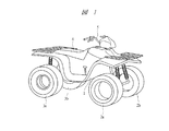
以下、本発明の実施の形態を図面に基づいて詳細に説明する。図1はバギー車とも言われるATVつまり全地形走行車の一例を示す斜視図であり、車体1には前輪2a,2bと後輪3a,3bが設けられており、鞍乗り型の座席4が車体1の中央部に設けられている。座席4に着座した乗員はハンドル5を操作して走行することになる。
Hereinafter, embodiments of the present invention will be described in detail with reference to the drawings. FIG. 1 is a perspective view showing an example of an ATV, which is also called a buggy vehicle, that is, an all-terrain vehicle. The vehicle body 1 is provided with
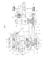
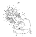
図2は図1に示された全地形走行車に搭載される動力伝達装置を示す概略図であり、図3は図2におけるA−A線に沿う方向の断面図である。図2に示すように、第1ケース体11aと第2ケース体11bとを突き合わせて組み立てられるクランクケース11にはクランク軸12が回転自在に装着されるとともに、図3に示すようにエンジン13が取り付けられている。エンジン13は、図3に示すように、クランクケース11に固定されるシリンダ14と、このシリンダ14の上端に固定されるシリンダヘッド15とを有している。シリンダ14に形成されたシリンダボア内にはピストン16が往復動自在に組み込まれ、クランク軸12にその回転中心から偏心した位置に固定されたクランクピン17とピストン16との間にはコネクティングロッド18が連結され、エンジン13によりクランク軸12は回転駆動される。
2 is a schematic view showing a power transmission device mounted on the all-terrain vehicle shown in FIG. 1, and FIG. 3 is a cross-sectional view taken along the line AA in FIG. As shown in FIG. 2, a
図3に示すように、シリンダヘッド15には燃焼室19に開口して吸気ポート21aが形成され、この吸気ポート21aを開閉するための吸気弁22aがシリンダヘッド15に装着されている。また、シリンダヘッド15には燃焼室19に開口して排気ポート21bが形成され、この排気ポート21bを開閉するための排気弁22bがシリンダヘッド15に装着されている。シリンダヘッド15には、カムシャフト23が回転自在に装着され、これと平行に設けられたロッカシャフト24には、吸気弁22aを開閉駆動するためのロッカアーム25aと、排気弁22bを開閉駆動するためのロッカアーム25bとが回動自在に装着されている。図2に示すように、クランク軸12にはスプロケット26が固定され、カムシャフト23に固定された図示しないスプロケットとの間にはタイミングチェーン(図示省略)が掛け渡されており、吸気弁22aと排気弁22bはクランク軸12の回転によりカムシャフト23およびロッカアーム25a,25bを介して所定のタイミングで開閉駆動される。
As shown in FIG. 3, the
図2に示すように、クランクケース11には変速機ケース31が取り付けられ、この変速機ケース31の内部にはベルト式の無段変速機32が組み込まれている。無段変速機32はクランク軸12に同軸状となって変速機ケース31内に回転自在に装着されるプライマリ軸33と、このプライマリ軸33に平行となって回転自在に変速機ケース31内に回転自在に装着されるセカンダリ軸34とを有し、プライマリ軸33はこれとクランク軸12との間に組み込まれる遠心クラッチ35のクラッチドラム36に連結されている。
As shown in FIG. 2, a
プライマリ軸33には溝幅可変のプライマリプーリ37が組み付けられており、プライマリプーリ37はプライマリ軸33に固定されてこれと一体に回転する固定プーリ37aと、プライマリ軸33に対して軸方向に移動自在に組み付けられてプライマリ軸33と一体に回転する可動プーリ37bとにより構成される。セカンダリ軸34には溝幅可変のセカンダリプーリ38が組み付けられており、セカンダリプーリ38はセカンダリ軸34に固定されてこれと一体に回転する固定プーリ38aと、セカンダリ軸34に対して軸方向に移動自在に組み付けられてセカンダリ軸34と一体に回転する可動プーリ38bとにより構成される。これらのプーリ37,38の間には、ゴム製のVベルト39が掛け渡されており、Vベルト39のプライマリプーリ37とセカンダリプーリ38とに対する巻き付け径が変化すると、プライマリ軸33の回転は無段階に変速比が変化してセカンダリ軸34に伝達される。プライマリプーリ37には、プライマリ軸33に固定されたカムプレート41により、プライマリ軸33の回転中心に対して直角方向を向いて円柱形状の遠心ウエイト42が複数個装着されており、セカンダリ軸34には、Vベルト39への締め付け力を加えるために、圧縮コイルばね43が装着されている。
A
したがって、クランク軸12が所定以上の回転数となって遠心クラッチ35を介してプライマリ軸33とクランク軸12とが締結された状態のもとで、プライマリ軸33の回転数が高くなると、遠心ウエイト42はこれに加わる遠心力により径方向外方に向けて移動し、プライマリプーリ37の溝幅が狭められてこのプーリ37に対する巻き付け径が大きくなる。これにより、セカンダリプーリ38の溝幅がばね力に抗して広がってVベルト39のセカンダリプーリ38に対する巻き付け径が小さくなり、無段変速機32の変速比は高速段側に変化する。
Therefore, when the rotation speed of the
変速機ケース31には図2に示すようにギヤケース44が組み付けられ、このギヤケース44にはセカンダリ軸34が支持されるとともに、セカンダリ軸34に平行となって出力軸45が回転自在に装着され、さらに出力軸45に平行となって車軸46が回転自在に装着されており、車軸46は図1に示した後輪3a,3bに直接連結されている。セカンダリ軸34と出力軸45との間には、セカンダリ軸34に一体に設けられた歯車と出力軸45に回転自在に装着された歯車とからなる正転用の歯車列47が設けられるとともに、セカンダリ軸34に一体に設けられた歯車と出力軸45に回転自在に装着される歯車とこれに噛み合う図示しないアイドラー歯車とからなる逆転用の歯車列48が設けられている。
As shown in FIG. 2, a
出力軸45の回転方向を正転方向と逆転方向に切り換えるために、出力軸45には前後進切換機構49が装着されている。前後進切換機構49は、図2に示すように、出力軸45に設けられたスプラインにそれぞれ噛み合う切換ディスク51a,51bを有しており、これらの切換ディスク51a,51bは出力軸45に軸方向に摺動自在に装着されている。切換ディスク51aを歯車列47に係合させると、セカンダリ軸34の回転は正転方向となって車軸46に伝達され車両は前進移動する。一方、切換ディスク51bを歯車列48に係合させると、セカンダリ軸34の回転は逆転方向となって車軸46に伝達され、車両は後退移動する。
In order to switch the rotation direction of the
図2に示すように、クランクケース11にはクランク軸12に平行にバランサ軸52が回転自在に装着され、バランサ軸52はクランク軸12に固定された駆動歯車53aとバランサ軸52に固定された従動歯車53bとからなる歯車列53を介してクランク軸12に連結されている。バランサ軸52にはバランスウエイト54が一体に設けられるとともに、クランクケース11に装着されたオイルポンプ55のロータに連結されており、このオイルポンプ55から吐出される潤滑油は、動力伝達装置における摺動部に図示しない油路を介して供給されるようになっている。
As shown in FIG. 2, a
クランクケース11には、図2に示すように、発電体ケース56が取り付けられており、発電体ケース56内には発電体57が装着されるようになっており、発電体57はクランク軸12に取り付けられるアウターロータ58と、クランクケース11に取り付けられるステータ59とを有している。したがって、エンジン13が駆動されてクランク軸12が回転すると、発電体57により発電された電力が図示しないバッテリに充電される。
As shown in FIG. 2, a
クランクケース11、変速機ケース31および発電体ケース56により動力伝達装置を構成するための上述した部材を収容するケースが形成されており、このケースを車体に取り付けることにより動力伝達装置は車体に搭載される。
The
エンジンを始動させるために、発電体ケース56内にはスタータ61が装着され、このスタータ61はクランクケース11に取り付けられた電動モータ62により駆動されるようになっている。バッテリの充電量が不足してエンジン13をスタータ61により始動できないときに、手動でエンジン13を始動させるために、発電体ケース56内にはリコイルスタータ63が装着されている。リコイルスタータ63は、リコイルロープが巻き付けられたリコイルプーリ64を有し、リコイルロープを引いてリコイルプーリ64を回転させるとクランク軸12が回転し、エンジン13を手動でも始動させることができる。
In order to start the engine, a
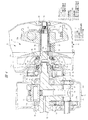
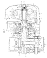
図4は図2の一部を拡大して示す断面図であり、クランク軸12はケース体11aに設けられるクランク軸用の軸受66と、ケース体11bに設けられるクランク軸用の軸受67とによりケースつまりクランクケース11に回転自在に支持されている。一方の軸受66は歯車53aを介してクランク軸12のバランスウエイト部12aに隣接し、他方の軸受67はクランク軸12のバランスウエイト部12bに隣接しており、それぞれの軸受66,67はバランスウエイト部12a,12bに対して外側に配置されている。
FIG. 4 is an enlarged cross-sectional view of a part of FIG. 2. The
クランク軸12の無段変速機32側の端部には、インナープレート68がクランク軸12に対して径方向を向いて設けられており、このインナープレート68はクランク軸12にスプライン結合されるボス部69によりクランク軸12に固定され、ボス部69はナット70によりクランク軸12に締結されている。インナープレート68には、これに固定された支持ピン71により遠心ウエイトシュー72が回動自在に取り付けられており、遠心ウエイトシュー72にはその自由端の部分がクラッチドラム36の内面から離れる方向のばね力がコイルばね73により加えられている。クランク軸12の回転数が所定値以上となると、遠心力により遠心ウエイトシュー72は外方に回動してその自由端の部分がクラッチドラム36の内周面に接触してクラッチドラム36がクランク軸12と一体に回転し、その回転がプライマリ軸33に伝達される。
An
プライマリ軸33には固定プーリ37aがスプライン結合され、固定プーリ37aの内面に一端面を突き当てるようにプライマリ軸33には円筒形状のカラー74が嵌合されており、カラー74の外周面に形成されたスプラインに可動プーリ37bが噛み合って可動プーリ37bは軸方向に摺動自在となっている。カラー74の他端面に突き当てるようにプライマリ軸33にはカムプレート41が固定され、プライマリ軸33の外側端部にねじ結合されるナット75により固定プーリ37aと、カラー74と、カムプレート41とがプライマリ軸33に締結されている。
A fixed
プライマリ軸33のクランク軸側端部つまり内側端部76には、クラッチドラム36に固定されるフランジ部77aとジャーナル部77bとが設けられ、プライマリ軸33にはフランジ部77aとジャーナル部77bとに対応させて凹部78が形成されており、この凹部78の中にクランク軸12の端部に設けられたボス部69とナット70が入り込んでいる。プライマリ軸33の内側端部76のジャーナル部77bには第1の変速機用の軸受81の内輪が嵌合し、この軸受81の外輪は変速機ケース31に設けられてこれの一部を構成する仕切り壁31aに嵌合しており、内輪の一方の端面はフランジ部77aに突き当てられ、外輪の他方の端面は仕切り壁31aの径方向面に突き当てられており、プライマリ軸33の内側端部76は軸受81により仕切り壁31aに回転自在に支持されている。一方、プライマリ軸33の外側端部79には第2の変速機用の軸受82の内輪が嵌合し、この軸受82の外輪は変速機ケース31の取付孔に嵌合しており、プライマリ軸33の外側端部79はケースに回転自在に支持されている。
The crankshaft side end portion, that is, the
このように、プライマリ軸33はその内側端部76の外周面に嵌合する軸受81と、外側端部79の外周面に嵌合する軸受82とにより回転自在にケースに支持されており、プライマリ軸33にはフランジ部77aを介してクラッチドラム36が一体となって固定されているので、軸受81は遠心クラッチ35のクラッチドラム36をも回転自在に変速機ケース31に支持している。したがって、動力伝達時にクランク軸12とプライマリ軸33とに応力が加わっても、クランク軸12とクラッチドラム36との間に小型の軸受を設けることなく、クランク軸12とプライマリ軸33を2つのクランク軸用の軸受66,67と2つの変速機用の軸受81,82との合計4つの軸受により同軸状に、つまりそれぞれの軸の回転中心軸が一致するように支持することができる。このようにクランク軸12とプライマリ軸33とが同軸状に支持されるので、クランク軸12の回転数が所定値以上となると、クラッチドラム36の内周面に遠心ウエイトシュー72の自由端部が接触して確実にクランク軸12の回転をプライマリ軸33に伝達することができる。
Thus, the
内側端部76には軸受81と固定プーリ37aとの間に挟み込まれるようにリング83が嵌合され、軸受81の内輪はフランジ部77aとリング83との間に挟み込まれており、ナット75を締め付けると、ナット75によりプライマリ軸33に加えられるスラスト方向つまり軸方向の締結力が軸受81に対する締結力となってフランジ部77aとリング83とにより加えられる。したがって、ナット75によりプライマリ軸33の内部に応力を発生させた状態で、クラッチドラム36とプライマリプーリ37とをプライマリ軸33を介して組み立てることができ、内部応力により軸受81に締め付け力を加えた状態としてクラッチドラム36とプライマリ軸33とを強固に組み合わせることができる。
A
図5は本発明の他の実施の形態である動力伝達装置であって、図4と同様の部分を示す断面図であり、図5においては前述した実施の形態における部材と共通の部材には同一の符号が付されている。この動力伝達装置においては、図4に示したリング83が設けられておらず、固定プーリ37aはジャーナル部77bの端面に突き当てられており、ジャーナル部77bに形成された取付溝には環状の止め具であるサークリップ84が止め付けられるようになっており、このサークリップ84とフランジ部77aにより軸受81の内輪が固定される。
FIG. 5 is a power transmission device according to another embodiment of the present invention, and is a cross-sectional view showing the same part as in FIG. 4. In FIG. The same code | symbol is attached | subjected. In this power transmission device, the
図5に示す場合には、軸受81の外輪を仕切り壁31aに固定するために、蓋部材85が仕切り壁31aに取り付けられており、さらにこの蓋部材85には、クランク室内の潤滑油が無段変速機32内に流入するのを防止するためのメカニカルシール86が装着されている。図4に示す場合には、メカニカルシール86は仕切り壁31aとリング83との間に装着されている。
In the case shown in FIG. 5, a lid member 85 is attached to the
上述のように、本発明の動力伝達装置においては、遠心クラッチ35のクラッチドラム36とプライマリ軸33とを内側端部76の部分で一体化したので、2つの軸受81,82によりプライマリ軸33とクラッチドラム36とを回転自在にケースに支持することができ、クランク軸12とクラッチドラム36との間に小型の軸受を装着することが不要となり、軸受の数を従来よりも低減することができるとともに、動力伝達装置の組立性を向上させることができる。
As described above, in the power transmission device of the present invention, the
本発明は前記実施の形態に限定されるものではなく、その要旨を逸脱しない範囲で種々変更可能である。たとえば、本発明の動力伝達装置は、クランク軸12とベルト式無段変速機のプライマリ軸33とが同軸状に配置され、クランク軸12とプライマリ軸33との間に遠心クラッチ35が装着されるようになったATV車両に適用することができ、エンジン13の種類は4サイクルエンジンに限られることはなく、2サイクルエンジンを搭載するようにしても良い。
The present invention is not limited to the above-described embodiment, and various modifications can be made without departing from the scope of the invention. For example, in the power transmission device of the present invention, the
11 クランクケース
12 クランク軸
32 ベルト式無段変速機
33 プライマリ軸
34 セカンダリ軸
35 遠心クラッチ
36 クラッチドラム
37 プライマリプーリ
37a 固定プーリ
37b 可動プーリ
66 軸受(クランク軸用の軸受)
67 軸受(クランク軸用の軸受)
68 インナープレート
72 遠心ウエイトシュー
74 カラー
75 ナット
76 内側端部
77a フランジ部
77b ジャーナル部
78 凹部
81 軸受(第1の変速機用の軸受)
82 軸受(第2の変速機用の軸受)
83 リング
84 サークリップ(止め具)
85 蓋部材
86 メカニカルシール
11 Crankcase 12
67 Bearing (bearing for crankshaft)
68
82 Bearing (bearing for the second transmission)
83
85
Claims (4)
前記クランク軸を当該クランク軸のバランスウエイト部の外側で支持するクランク軸用の軸受を前記ケースに設け、
前記クランク軸に装着されるインナープレートとにより前記遠心クラッチを構成するクラッチドラムを前記プライマリ軸の内側端部に固定し、
前記内側端部に嵌合される第1の変速機用の軸受と、前記プライマリ軸の外側端部に嵌合される第2の変速機用の軸受とを前記ケースに設け、
前記プライマリ軸を前記外側端部と前記クラッチドラムに固定される前記内側端部とで回転自在に支持することを特徴とするエンジンの動力伝達装置。 A crankshaft rotatably mounted on the case, and a primary shaft of a belt-type continuously variable transmission that is provided coaxially with the crankshaft and is provided with a variable pulley primary pulley having a fixed pulley and a movable pulley; A power transmission device for an engine having a centrifugal clutch mounted between the crankshaft and the primary shaft and transmitting engine power to drive wheels,
A crankshaft bearing that supports the crankshaft outside the balance weight portion of the crankshaft is provided in the case,
A clutch drum constituting the centrifugal clutch is fixed to an inner end of the primary shaft by an inner plate attached to the crankshaft,
A bearing for the first transmission fitted to the inner end and a bearing for the second transmission fitted to the outer end of the primary shaft are provided in the case;
An engine power transmission device, wherein the primary shaft rotatably supports the outer end portion and the inner end portion fixed to the clutch drum.
3. The engine power transmission device according to claim 1, wherein an inner ring of a bearing for the first transmission is fixed to the primary shaft by a stopper provided at the inner end, and is attached to the case and the case. A power transmission device for an engine, wherein an outer ring of a bearing for the first transmission is fixed to the case by a lid member.
Priority Applications (3)
| Application Number | Priority Date | Filing Date | Title |
|---|---|---|---|
| JP2004111326A JP2005291472A (en) | 2004-04-05 | 2004-04-05 | Engine power transmission device |
| US11/094,197 US20050221927A1 (en) | 2004-04-05 | 2005-03-31 | Power transmission system of engine |
| CA002503915A CA2503915A1 (en) | 2004-04-05 | 2005-04-04 | Power transmission system of engine |
Applications Claiming Priority (1)
| Application Number | Priority Date | Filing Date | Title |
|---|---|---|---|
| JP2004111326A JP2005291472A (en) | 2004-04-05 | 2004-04-05 | Engine power transmission device |
Publications (1)
| Publication Number | Publication Date |
|---|---|
| JP2005291472A true JP2005291472A (en) | 2005-10-20 |
Family
ID=35055094
Family Applications (1)
| Application Number | Title | Priority Date | Filing Date |
|---|---|---|---|
| JP2004111326A Pending JP2005291472A (en) | 2004-04-05 | 2004-04-05 | Engine power transmission device |
Country Status (3)
| Country | Link |
|---|---|
| US (1) | US20050221927A1 (en) |
| JP (1) | JP2005291472A (en) |
| CA (1) | CA2503915A1 (en) |
Cited By (3)
| Publication number | Priority date | Publication date | Assignee | Title |
|---|---|---|---|---|
| CN102421619A (en) * | 2009-05-14 | 2012-04-18 | 马来西亚国家石油公司 | Transmission system |
| JP2013137081A (en) * | 2011-12-28 | 2013-07-11 | Toyota Motor Corp | Dry belt-type continuously variable transmission |
| CN109854688A (en) * | 2018-12-14 | 2019-06-07 | 辛集市宇泰机械有限公司 | Automobile gearbox |
Families Citing this family (7)
| Publication number | Priority date | Publication date | Assignee | Title |
|---|---|---|---|---|
| JP4767603B2 (en) * | 2005-07-04 | 2011-09-07 | ヤマハ発動機株式会社 | Power unit and straddle-type vehicle equipped with the power unit |
| US7604557B2 (en) * | 2005-12-19 | 2009-10-20 | Kwang Yang Motor Co., Ltd. | Vehicle transmission |
| JP2007321790A (en) * | 2006-05-30 | 2007-12-13 | Yamaha Motor Co Ltd | Engine unit and saddle riding type vehicle |
| JP4545131B2 (en) * | 2006-09-29 | 2010-09-15 | 本田技研工業株式会社 | Power transmission device |
| US20080102997A1 (en) * | 2006-10-27 | 2008-05-01 | Kwang Yang Motor Co., Ltd. | Vehicle transmission |
| ITMI20112250A1 (en) * | 2011-12-13 | 2013-06-14 | Piaggio & C Spa | TRANSMISSION SYSTEM WITH DEVICE FOR ADJUSTING THE CHANGE CURVE |
| US10422417B2 (en) * | 2017-06-25 | 2019-09-24 | Wang-chang Wu | Pulley assembly for high-speed continuously variable transmission |
Family Cites Families (8)
| Publication number | Priority date | Publication date | Assignee | Title |
|---|---|---|---|---|
| IT1194395B (en) * | 1983-09-09 | 1988-09-22 | Piaggio & C Spa | VARIABLE RATIO TRANSMISSION SYSTEM, USEFUL PARTICULARLY FOR VEHICLES |
| US5394853A (en) * | 1992-04-22 | 1995-03-07 | Tochigi Fuji Sangyo Kabushiki Kaisha | Supercharging device for an internal combustion engine |
| JP3526653B2 (en) * | 1995-05-16 | 2004-05-17 | 株式会社共立 | Portable work machine |
| US6269899B1 (en) * | 1997-04-28 | 2001-08-07 | Yamaha Hatsudoki Kabushiki Kaisha | Transmission for offroad vehicle |
| EP1286075B1 (en) * | 1999-03-09 | 2004-05-12 | Nsk Ltd | Clutch release bearing |
| JP4752089B2 (en) * | 2000-05-17 | 2011-08-17 | トヨタ自動車株式会社 | Belt type continuously variable transmission |
| JP2004156658A (en) * | 2002-11-05 | 2004-06-03 | Yamaha Motor Co Ltd | engine |
| JP4140034B2 (en) * | 2004-03-05 | 2008-08-27 | トヨタ自動車株式会社 | Belt type continuously variable transmission for vehicles |
-
2004
- 2004-04-05 JP JP2004111326A patent/JP2005291472A/en active Pending
-
2005
- 2005-03-31 US US11/094,197 patent/US20050221927A1/en not_active Abandoned
- 2005-04-04 CA CA002503915A patent/CA2503915A1/en not_active Abandoned
Cited By (4)
| Publication number | Priority date | Publication date | Assignee | Title |
|---|---|---|---|---|
| CN102421619A (en) * | 2009-05-14 | 2012-04-18 | 马来西亚国家石油公司 | Transmission system |
| CN102421619B (en) * | 2009-05-14 | 2015-11-25 | 马来西亚国家石油公司 | transmission system |
| JP2013137081A (en) * | 2011-12-28 | 2013-07-11 | Toyota Motor Corp | Dry belt-type continuously variable transmission |
| CN109854688A (en) * | 2018-12-14 | 2019-06-07 | 辛集市宇泰机械有限公司 | Automobile gearbox |
Also Published As
| Publication number | Publication date |
|---|---|
| US20050221927A1 (en) | 2005-10-06 |
| CA2503915A1 (en) | 2005-10-05 |
Similar Documents
| Publication | Publication Date | Title |
|---|---|---|
| US7243564B2 (en) | Power transmission system of engine | |
| JP3709973B2 (en) | Belt-type transmission | |
| US7600625B2 (en) | Centrifugal clutch | |
| JP4463202B2 (en) | Continuously variable transmission engine | |
| KR100672290B1 (en) | One-way clutch | |
| JP2005291472A (en) | Engine power transmission device | |
| US7107865B2 (en) | Power transmission apparatus for vehicle | |
| JP2004360520A (en) | Four-stroke engine equipped with belt-type continuously variable transmission mechanism | |
| US20080182688A1 (en) | Power unit for small vehicle | |
| JP2005319920A (en) | Engine power transmission device | |
| US6607048B2 (en) | Motor assisting apparatus for vehicle | |
| JP2006342815A (en) | V belt type continuously variable transmission engine | |
| CN100400821C (en) | Engine with built-in continuously variable transmission | |
| JPH0718349B2 (en) | Winding transmission device for internal combustion engine | |
| CN101382084A (en) | power unit | |
| JP4494235B2 (en) | Clutch lubrication equipment | |
| US7648010B2 (en) | Starting clutch | |
| JP3559320B2 (en) | Support structure for crankshaft of internal combustion engine | |
| WO2003095868A1 (en) | Vehicle with continuously variable transmission | |
| US20040209725A1 (en) | Power transmission system of engine | |
| JP2002235550A (en) | Auxiliary equipment for engines | |
| JP2001180563A (en) | Transmission of unit swing type engine | |
| JP4177687B2 (en) | Overhead cam type engine | |
| JP2005291473A (en) | Clutch lubrication equipment | |
| JP2005090375A (en) | Engine lubrication equipment |