JP2005291454A - Wiring fixing structure - Google Patents
Wiring fixing structure Download PDFInfo
- Publication number
- JP2005291454A JP2005291454A JP2004110828A JP2004110828A JP2005291454A JP 2005291454 A JP2005291454 A JP 2005291454A JP 2004110828 A JP2004110828 A JP 2004110828A JP 2004110828 A JP2004110828 A JP 2004110828A JP 2005291454 A JP2005291454 A JP 2005291454A
- Authority
- JP
- Japan
- Prior art keywords
- fixing
- wiring
- groove
- base
- hollow
- Prior art date
- Legal status (The legal status is an assumption and is not a legal conclusion. Google has not performed a legal analysis and makes no representation as to the accuracy of the status listed.)
- Withdrawn
Links
- 238000000605 extraction Methods 0.000 claims description 3
- 238000005266 casting Methods 0.000 description 4
- 239000013013 elastic material Substances 0.000 description 2
- 238000003780 insertion Methods 0.000 description 2
- 230000037431 insertion Effects 0.000 description 2
- 238000004519 manufacturing process Methods 0.000 description 2
- 238000000034 method Methods 0.000 description 2
- 230000002093 peripheral effect Effects 0.000 description 2
- 238000009429 electrical wiring Methods 0.000 description 1
- -1 for example Substances 0.000 description 1
Images
Landscapes
- Connection Of Plates (AREA)
- Clamps And Clips (AREA)
Abstract
Description
本発明は、機器・装置などにおいて電線等の配線を束ね固定するのに固定位置に自由度があり、また固定作業を容易に行うことができる、配線固定構造に関する。 The present invention relates to a wiring fixing structure in which a fixing position has a degree of freedom for bundling and fixing wirings such as electric wires in devices and apparatuses, and the fixing operation can be easily performed.
例えば、アクチュエータの作動を制御する油圧制御弁の弁本体、そして弁本体に取り付けられた種々の電磁弁、圧力スイッチ、センサーなどには、多くの電気配線、配管が接続されている。 For example, many electric wires and pipes are connected to a valve body of a hydraulic control valve that controls the operation of an actuator, and various electromagnetic valves, pressure switches, sensors, and the like attached to the valve body.
これらの電気配線、配管は、周囲の機器、構造物などと干渉しないように、クリップ、クランプなどの配線固定具によって適宜に束ねられ、配線固定具は弁本体に予め備えられたねじ穴にボルトによって、あるいは機器類を取り付けているボルトを兼用して、固定されている(例えば、特許文献1参照)。
しかしながら、上述したとおりの形態の従来の配線固定構造には、次のとおりの解決の望まれている問題がある。 However, the conventional wiring fixing structure of the form as described above has a problem that is desired to be solved as follows.
配線が固定される油圧制御弁の弁本体のような鋳物によって形成される部材は製作に多くの日数が必要である。したがって、電気配線が計画される後工程の段階では配線固定用のねじ穴が間に合わない、また所望の位置に後から追加加工することは鋳物の形状、肉厚などから実質上できないことがある。鋳物構造の制御弁を計画する時期に配線固定用のねじ穴の位置を決めるのは困難であり、推測でねじ穴位置を決めておくと、位置が不適切、不必要なねじ穴が加工されてしまう問題がある。 A member formed of a casting, such as a valve body of a hydraulic control valve to which wiring is fixed, requires many days to manufacture. Therefore, the screw holes for fixing the wiring are not in time at the post-process stage where the electrical wiring is planned, and it may be impossible to perform additional processing at a desired position later due to the shape and thickness of the casting. It is difficult to determine the position of the screw hole for fixing the wiring at the time of planning the control valve of the cast structure. If the screw hole position is determined by estimation, the position is inappropriate and unnecessary screw holes are processed. There is a problem.
したがって、適切な位置に配線が固定されないと、配線は周囲の構造物と干渉し損傷されやすくなり、また配線の見映えも悪くなる。 Therefore, if the wiring is not fixed at an appropriate position, the wiring easily interferes with surrounding structures and is damaged, and the appearance of the wiring also deteriorates.
配線固定用のねじ穴を適切な位置に用意できない場合には、固定用に支持板のような配線支持部材を別途用意する必要があり、その設計が必要になり、部品点数が多くなり、また製品のコストも高くなる。 If the screw holes for fixing the wiring cannot be prepared at an appropriate position, it is necessary to separately prepare a wiring support member such as a support plate for fixing, which requires a design, increases the number of parts, and Product costs also increase.
さらに、配線の固定作業には、クリップ、クランプなどの配線固定具をボルト、ワッシャなどを用いて固定するので、工具が必要である。 Furthermore, the wiring fixing work requires tools because the wiring fixing tools such as clips and clamps are fixed using bolts, washers and the like.
本発明は上記事実に鑑みてなされたもので、その技術的課題は、機器・装置などにおいて電線、配管などを束ね固定するのに、その位置を自由に変えることができ、かつ位置の変更に新規に部品を追加する必要がなく、さらに工具を用いないで固定作業を容易に行なうことができる、配線固定構造を提供することである。 The present invention has been made in view of the above-mentioned facts, and its technical problem is that the position can be freely changed and the position can be changed in order to bundle and fix electric wires, pipes and the like in equipment and devices. It is an object of the present invention to provide a wiring fixing structure that does not require new parts and that can be easily fixed without using a tool.
本発明によれば上記技術的課題を解決する配線固定構造として、配線を固定する固定部材に形成された所定の断面形状を有して延びる固定溝と、この固定溝内に移動を自在に嵌合され該溝の開放部側に開口された中空部を有する固定具と、この中空部に挿入された基部及び基部から延びる配線を固縛するためのバンド部を有したクリップを備え、該基部を中空部から抜き出す方向に移動させると、中空部と基部とが係合し、中空部からの基部の抜け出しが係止され、かつこの係合によって固定具が拡張され固定溝に固定される、ことを特徴とする配線固定構造が提供される。 According to the present invention, as a wiring fixing structure that solves the above technical problem, a fixing groove that has a predetermined cross-sectional shape formed in a fixing member that fixes a wiring, and a movement that fits freely in the fixing groove. A fixture having a hollow portion that is joined and opened to the open portion side of the groove, a base portion inserted into the hollow portion, and a clip having a band portion for securing a wiring extending from the base portion; Is moved in the direction of pulling out from the hollow portion, the hollow portion and the base portion are engaged, the withdrawal of the base portion from the hollow portion is locked, and by this engagement, the fixture is expanded and fixed to the fixing groove. A wiring fixing structure is provided.
好適には、該固定溝の断面形状が開放部から底部に向けて漸次拡がる台形状に形成され、該固定具がこの固定溝に嵌合する円錐台状に形成されている。また、該中空部は開口側が小径の円錐台状に形成され、該基部は該中空部の開口側が大径の逆円錐台状に形成され、該中空部の開口端部及び基部の大径端部に、基部と中空部とが係合する係合部が形成されている。そして、該係合部が、中空部に形成された環状溝と、基部に形成された環状突起を備えている。 Preferably, the cross-sectional shape of the fixing groove is formed in a trapezoidal shape that gradually expands from the open portion toward the bottom, and the fixing tool is formed in a truncated cone shape that fits in the fixing groove. Further, the hollow portion is formed in a truncated cone shape having a small diameter on the opening side, and the base portion is formed in an inverted truncated cone shape having a large diameter on the opening side of the hollow portion, and the opening end portion of the hollow portion and the large diameter end of the base portion An engaging portion where the base portion and the hollow portion engage is formed in the portion. The engaging portion includes an annular groove formed in the hollow portion and an annular protrusion formed in the base portion.
また、該係合部の固定具外周には、該固定溝の開放部の縁部に当接する環状凹部が形成され、延在する該固定溝の少なくとも一端側断面端が該固定具を挿入可能に開放されている。そして、該クリップは、バンド部の先端をバンド部の該基部側に形成された止め穴に通し形成した輪を締め上げることにより配線を固縛し、この締め上げによって該基部が固定具の中空部から引き出す方向に移動され、該クリップの固定具からの抜き出しが係止され、かつ固定具が固定溝に固定される。 Further, an annular recess is formed on the outer periphery of the fixing portion of the engaging portion so as to contact the edge of the opening portion of the fixing groove, and at least one end side cross-sectional end of the extending fixing groove can be inserted into the fixing groove. It is open to. The clip secures the wiring by tightening a ring formed by passing the tip of the band portion through a stop hole formed on the base side of the band portion, and the base portion is hollowed by the tightening by the tightening. The clip is moved in the direction to be pulled out, the extraction of the clip from the fixing tool is locked, and the fixing tool is fixed to the fixing groove.
本発明に従って構成された配線固定構造によれば、配線を固定する固定具及びクリップを固定溝に沿ってその中を自在に動かすことができ、かつ移動した位置において固定できるので、配線を固定する固定部材に固定溝を適宜に備えれば、任意の位置で配線を固定することができる。さらに、クリップのバンド部によって配線を固縛する動作により固定具が固定される。したがって、電線、配管などを束ね固定するのに、その位置を自由に変えることができ、また位置の変更に新規に部品を追加する必要がなく、さらに工具を用いないで固定作業を容易に行なうことができる。 According to the wiring fixing structure configured according to the present invention, the fixing tool and the clip for fixing the wiring can be moved freely along the fixing groove and can be fixed at the moved position, so that the wiring is fixed. If the fixing member is appropriately provided with a fixing groove, the wiring can be fixed at an arbitrary position. Further, the fixture is fixed by the operation of securing the wiring by the band portion of the clip. Therefore, when bundling and fixing wires, pipes, etc., the position can be freely changed, and there is no need to add new parts to change the position, and the fixing work can be easily performed without using a tool. be able to.
なお、本発明の配線固定構造は、「電線」の固定に限定されるものではなく「配管」の固定にも適用することができる。 The wiring fixing structure of the present invention is not limited to fixing “electric wires” but can also be applied to fixing “piping”.
以下、本発明に従って構成された配線固定構造について、好適実施形態を図示している添付図面を参照して、さらに詳細に説明する。 Hereinafter, a wiring fixing structure configured according to the present invention will be described in more detail with reference to the accompanying drawings illustrating preferred embodiments.
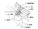
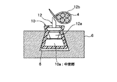
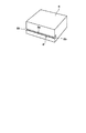
配線固定構造の斜視図である図1及び断面図である図2を参照して説明する。全体を番号2で示す配線固定構造は、配線4を固定する固定部材6に形成された所定の断面形状を有して延びる固定溝8と、固定溝8内に移動を自在に嵌合され溝8の開放部8a側に開口された中空部10aを有する固定具10と、この中空部10aに挿入された基部12a及び基部12aから延び配線4を固縛するためのバンド部12bを有したクリップ12を備えている。図1及び図2はバンド部12bによって配線4が固縛され固定具10が固定溝8に固定された状態を示している。
The wiring fixing structure will be described with reference to FIG. 1 which is a perspective view and FIG. 2 which is a cross-sectional view. The wiring fixing structure generally indicated by reference numeral 2 has a
固定溝8の断面形状は、開放部8aから底部に向けて漸次拡がる台形状に形成されている。固定具10はこの溝8に嵌合する円錐台状に形成されている。
The cross-sectional shape of the
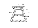
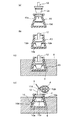
固定具10の拡大断面図である図3を参照して説明する。固定具10は、弾性材料、例えばプラスチックによって形成されている。中空部10aは溝8の開放部8a側が小径の円錐台状に形成され、中空部10aの開口端部には、半径方向外方に突出しクリップ12の基部12aと係合する係合部Kを構成する環状溝10bが形成されている。また、係合部Kの外周と円錐台の外周斜面によって、固定溝8の開放部8aの縁部に当接する環状凹部10cが形成されている。さらに中空部10aには、挿入されたクリップ12の基部12aを固定具10を固定溝8に固定した状態において支持する半径方向内方にリップ状に延びた環状リップ10dが形成されている。
The
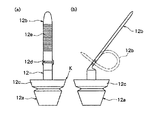
クリップ12の拡大側面図である図4を参照して説明する。図4(a)及び図4(b)はクリップ12を互いに側方から見た図である。クリップ12は、弾性材料、例えばプラスチックによって形成されている。基部12aは溝8の開放部8a側を大径にした逆円錐台状に形成され、大径端部には、半径方向外方に突出し中空部10aと係合する係合部Kを構成する環状突起12cが形成されている。基部12aの大径端部にバンド部12bが帯状に延びて一体に形成されている。バンド部12bの基部12a側には帯状のバンド部12bをその先端から通し固定できる大きさの矩形の止め穴12dが形成され、バンド部12bの表面には鋸歯状ノッチ12eが形成されている。
The
かくして、図4(b)に二点鎖線で示すようにバンド部12bの先端を止め穴12dに通して形成した輪を締め上げることにより、締め上げた状態が鋸歯状ノッチ12eと止め穴12dによって維持され、この輪によって配線を固縛することができる。
Thus, as shown by a two-dot chain line in FIG. 4 (b), by tightening the ring formed by passing the tip of the
図5を参照して固定溝8の配設状態について説明する。固定溝8は配線が固定される固定部材6に延在する方向の両端の断面端8b、8bを開放して備えられている。この端部の開放は、固定具10を挿入することができるように固定溝8の少なくとも一端側が開放されていればよい。
The arrangement state of the
図6を参照して固定具10へのクリップ12の挿入、そして固定溝8への固定具10の固定について順を追って説明する。また、図7を参照して配線が固定される固定部材としての油圧制御弁6における配線の固定について説明する。
With reference to FIG. 6, the insertion of the
図6(a)(b):クリップ12の基部12aを固定具10の中空部10aに、その先端が中空部10a内の環状リップ10dを変形させ押し退ける位置まで挿入する。この状態においては固定具10の外周部は基部12aの挿入によって実質上拡張されない。
6 (a) and 6 (b): The
図6(c):クリップ12と一体になった固定具10を固定部材6の固定溝8内にその断面端8b(図5)から挿入し、配線を固定する位置まで固定溝8内を移動させる。
FIG. 6 (c): The
図6(d):クリップ12のバンド部12bにより配線4を束ねながらその先端を止め穴12dに通して固縛する。この締め上げるときに基部12aは固定具10の中空部10aから引き出す方向に移動され係合部Kが係合し、クリップ12の固定具10からの抜き出しが係止され、かつ固定具10の外周部が拡張され、固定溝8に固定される。
FIG. 6 (d): While the
さらにこのとき、固定具10の外周の環状凹部10cは固定溝8の開放部8aの縁部に圧接され、また固定具10の中空部10aの環状リップ10dによってクリップ12の基部12aの端が支持され、クリップ12は固定具10に、また固定具10は固定溝8に確実に固定保持される。
At this time, the
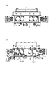
図7(a)は、固定部材である油圧制御弁6の配線前の状態を示し、油圧制御弁6には固定溝8が形成され、電気配線される複数個の電磁弁Eが組み込まれている。
FIG. 7A shows a state before wiring of the
図7(b)は、固定溝8に固定された固定具10及びクリップ12、2個所によって複数個の電磁弁Eにつながる配線4が束ねられ固定された状態を示している。
FIG. 7B shows a state in which the
上述したとおりの配線固定構造2の作用について説明する。 The operation of the wiring fixing structure 2 as described above will be described.
本発明に従って構成された配線固定構造2によれば、配線4を固定する固定具10及びクリップ12を固定溝8に沿ってその中を自在に動かすことができ、かつ移動した位置において固定できるので、配線4を固定する固定部材6に固定溝8を適宜に備えておけば、任意の位置で配線を固定することができる。さらに、クリップ12のバンド部12aによって配線4を固縛する動作により、クリップ12は固定具10に固定されるとともに固定具10は拡張され固定溝8に固定される。
According to the wiring fixing structure 2 configured according to the present invention, the fixing
したがって、電線、配管などを束ね固定するのにその位置を自由に変えることができ、適切な位置にすることができ、また位置の変更に新規に部品を追加する必要がなく、さらに工具を用いないで固定作業を容易に行なうことができるので、配線設計工数の削減、配線固定のための部品の削減により組立工数、部品コストも抑えることができる。 Therefore, it is possible to freely change the position for bundling and fixing wires, pipes, etc., to make it an appropriate position, and there is no need to add new parts to change the position. Therefore, the fixing work can be easily performed, so that the number of man-hours for assembly and the part cost can be reduced by reducing the number of wiring design steps and the number of parts for fixing the wiring.
さらに、配線が固定される部材が鋳物のような製作に時間を要するものであっても、初期計画の段階から固定溝を形成しておくことができ鋳物設計がしやすく追加加工も必要なくなる。 Furthermore, even if the member to which the wiring is fixed takes a long time to manufacture, such as a casting, a fixing groove can be formed from the initial planning stage, which facilitates casting design and eliminates the need for additional processing.
2:配線固定構造
4:配線
6:油圧制御弁(固定部材)
8:固定溝
8a:開放部
10:固定具
10a:中空部
12:クリップ
12a:基部
12b:バンド部
2: Wiring fixing structure 4: Wiring 6: Hydraulic control valve (fixing member)
8: Fixing
Claims (7)
該基部を中空部から抜き出す方向に移動させると、中空部と基部とが係合し、中空部からの基部の抜け出しが係止され、かつこの係合によって固定具が拡張され固定溝に固定される、ことを特徴とする配線固定構造。 A fixing groove having a predetermined cross-sectional shape formed on a fixing member for fixing the wiring, and a hollow portion that is movably fitted in the fixing groove and opened to the open portion side of the groove. And a clip having a base part inserted into the hollow part and a band part for securing the wiring extending from the base part,
When the base portion is moved in the direction of extracting from the hollow portion, the hollow portion and the base portion engage with each other, and the removal of the base portion from the hollow portion is locked, and by this engagement, the fixture is expanded and fixed to the fixing groove. Wiring fixing structure characterized by that.
該中空部の開口端部及び基部の大径端部に、基部と中空部とが係合する係合部が形成されている、請求項2記載の配線固定構造。 The hollow portion is formed in a truncated cone shape having a small diameter on the opening side, and the base portion is formed in an inverted truncated cone shape having a large diameter on the opening side of the hollow portion,
The wiring fixing structure according to claim 2, wherein an engagement portion for engaging the base portion and the hollow portion is formed at the opening end portion of the hollow portion and the large-diameter end portion of the base portion.
Priority Applications (1)
| Application Number | Priority Date | Filing Date | Title |
|---|---|---|---|
| JP2004110828A JP2005291454A (en) | 2004-04-05 | 2004-04-05 | Wiring fixing structure |
Applications Claiming Priority (1)
| Application Number | Priority Date | Filing Date | Title |
|---|---|---|---|
| JP2004110828A JP2005291454A (en) | 2004-04-05 | 2004-04-05 | Wiring fixing structure |
Publications (1)
| Publication Number | Publication Date |
|---|---|
| JP2005291454A true JP2005291454A (en) | 2005-10-20 |
Family
ID=35324600
Family Applications (1)
| Application Number | Title | Priority Date | Filing Date |
|---|---|---|---|
| JP2004110828A Withdrawn JP2005291454A (en) | 2004-04-05 | 2004-04-05 | Wiring fixing structure |
Country Status (1)
| Country | Link |
|---|---|
| JP (1) | JP2005291454A (en) |
Cited By (1)
| Publication number | Priority date | Publication date | Assignee | Title |
|---|---|---|---|---|
| JP2022506255A (en) * | 2018-11-15 | 2022-01-17 | 玉程 江 | Assembled structural system and its applications |
-
2004
- 2004-04-05 JP JP2004110828A patent/JP2005291454A/en not_active Withdrawn
Cited By (2)
| Publication number | Priority date | Publication date | Assignee | Title |
|---|---|---|---|---|
| JP2022506255A (en) * | 2018-11-15 | 2022-01-17 | 玉程 江 | Assembled structural system and its applications |
| JP7171915B2 (en) | 2018-11-15 | 2022-11-15 | 玉程 江 | Assembled structural system and its application |
Similar Documents
| Publication | Publication Date | Title |
|---|---|---|
| EP1467135B1 (en) | Laterally adjustable clamp | |
| JP4519793B2 (en) | Support color | |
| US20210033222A1 (en) | Multi-conduit flexible retention mechanism | |
| CN111480026A (en) | Mounting fixture | |
| CN102113180A (en) | Apparatus for mounting a surveillance camera | |
| JP2007525936A (en) | Cable entry device for easy installation | |
| KR20020084112A (en) | Cable protective spring and method of fixing the cable protective spring | |
| JPH05346193A (en) | Remote control assembly with conduit anchor device | |
| US20180038537A1 (en) | Pipe joint device and method for manufacturing the same | |
| JP2005291454A (en) | Wiring fixing structure | |
| JP5974617B2 (en) | Conduit connector (CONDUITCONNECTOR) | |
| KR101867587B1 (en) | Tube Connector | |
| JP2008263746A (en) | Structure of holding linear body onto columnar body and holding method therefor | |
| JP5789502B2 (en) | Microphone mounting device | |
| KR200223916Y1 (en) | Clamp for binding cable | |
| JPH0634079A (en) | Pipe joint being installed in building | |
| KR200320801Y1 (en) | Electric wire protecting pipe of electric wire inserting pipe connector | |
| JP2005323439A (en) | Belt clamp | |
| JP6075201B2 (en) | connector | |
| JPH1113720A (en) | Clamp | |
| KR200300801Y1 (en) | Clip For Dividing The Wire Harness | |
| JP5785114B2 (en) | Instrument mounting member | |
| JP2005151671A (en) | Device and tool for fixing bush in conduit tube | |
| KR100542041B1 (en) | Piping / Duct Fixtures Using Metal Strips | |
| JP2024076507A (en) | Fixture |
Legal Events
| Date | Code | Title | Description |
|---|---|---|---|
| A300 | Withdrawal of application because of no request for examination |
Free format text: JAPANESE INTERMEDIATE CODE: A300 Effective date: 20070605 |