JP2005291319A - Belt type continuously variable transmission - Google Patents
Belt type continuously variable transmission Download PDFInfo
- Publication number
- JP2005291319A JP2005291319A JP2004105777A JP2004105777A JP2005291319A JP 2005291319 A JP2005291319 A JP 2005291319A JP 2004105777 A JP2004105777 A JP 2004105777A JP 2004105777 A JP2004105777 A JP 2004105777A JP 2005291319 A JP2005291319 A JP 2005291319A
- Authority
- JP
- Japan
- Prior art keywords
- driven pulley
- shaft
- pulley
- continuously variable
- bearing
- Prior art date
- Legal status (The legal status is an assumption and is not a legal conclusion. Google has not performed a legal analysis and makes no representation as to the accuracy of the status listed.)
- Pending
Links
Images
Classifications
-
- F—MECHANICAL ENGINEERING; LIGHTING; HEATING; WEAPONS; BLASTING
- F16—ENGINEERING ELEMENTS AND UNITS; GENERAL MEASURES FOR PRODUCING AND MAINTAINING EFFECTIVE FUNCTIONING OF MACHINES OR INSTALLATIONS; THERMAL INSULATION IN GENERAL
- F16H—GEARING
- F16H9/00—Gearings for conveying rotary motion with variable gear ratio, or for reversing rotary motion, by endless flexible members
- F16H9/02—Gearings for conveying rotary motion with variable gear ratio, or for reversing rotary motion, by endless flexible members without members having orbital motion
- F16H9/04—Gearings for conveying rotary motion with variable gear ratio, or for reversing rotary motion, by endless flexible members without members having orbital motion using belts, V-belts, or ropes
-
- F—MECHANICAL ENGINEERING; LIGHTING; HEATING; WEAPONS; BLASTING
- F16—ENGINEERING ELEMENTS AND UNITS; GENERAL MEASURES FOR PRODUCING AND MAINTAINING EFFECTIVE FUNCTIONING OF MACHINES OR INSTALLATIONS; THERMAL INSULATION IN GENERAL
- F16H—GEARING
- F16H63/00—Control outputs from the control unit to change-speed- or reversing-gearings for conveying rotary motion or to other devices than the final output mechanism
- F16H63/02—Final output mechanisms therefor; Actuating means for the final output mechanisms
- F16H63/30—Constructional features of the final output mechanisms
- F16H63/34—Locking or disabling mechanisms
- F16H63/3416—Parking lock mechanisms or brakes in the transmission
- F16H63/3425—Parking lock mechanisms or brakes in the transmission characterised by pawls or wheels
-
- F—MECHANICAL ENGINEERING; LIGHTING; HEATING; WEAPONS; BLASTING
- F16—ENGINEERING ELEMENTS AND UNITS; GENERAL MEASURES FOR PRODUCING AND MAINTAINING EFFECTIVE FUNCTIONING OF MACHINES OR INSTALLATIONS; THERMAL INSULATION IN GENERAL
- F16H—GEARING
- F16H63/00—Control outputs from the control unit to change-speed- or reversing-gearings for conveying rotary motion or to other devices than the final output mechanism
- F16H63/02—Final output mechanisms therefor; Actuating means for the final output mechanisms
- F16H63/30—Constructional features of the final output mechanisms
- F16H63/34—Locking or disabling mechanisms
- F16H63/3416—Parking lock mechanisms or brakes in the transmission
-
- F—MECHANICAL ENGINEERING; LIGHTING; HEATING; WEAPONS; BLASTING
- F16—ENGINEERING ELEMENTS AND UNITS; GENERAL MEASURES FOR PRODUCING AND MAINTAINING EFFECTIVE FUNCTIONING OF MACHINES OR INSTALLATIONS; THERMAL INSULATION IN GENERAL
- F16H—GEARING
- F16H55/00—Elements with teeth or friction surfaces for conveying motion; Worms, pulleys or sheaves for gearing mechanisms
- F16H55/32—Friction members
- F16H55/52—Pulleys or friction discs of adjustable construction
- F16H55/56—Pulleys or friction discs of adjustable construction of which the bearing parts are relatively axially adjustable
-
- F—MECHANICAL ENGINEERING; LIGHTING; HEATING; WEAPONS; BLASTING
- F16—ENGINEERING ELEMENTS AND UNITS; GENERAL MEASURES FOR PRODUCING AND MAINTAINING EFFECTIVE FUNCTIONING OF MACHINES OR INSTALLATIONS; THERMAL INSULATION IN GENERAL
- F16H—GEARING
- F16H9/00—Gearings for conveying rotary motion with variable gear ratio, or for reversing rotary motion, by endless flexible members
- F16H9/02—Gearings for conveying rotary motion with variable gear ratio, or for reversing rotary motion, by endless flexible members without members having orbital motion
- F16H9/04—Gearings for conveying rotary motion with variable gear ratio, or for reversing rotary motion, by endless flexible members without members having orbital motion using belts, V-belts, or ropes
- F16H9/12—Gearings for conveying rotary motion with variable gear ratio, or for reversing rotary motion, by endless flexible members without members having orbital motion using belts, V-belts, or ropes engaging a pulley built-up out of relatively axially-adjustable parts in which the belt engages the opposite flanges of the pulley directly without interposed belt-supporting members
- F16H9/16—Gearings for conveying rotary motion with variable gear ratio, or for reversing rotary motion, by endless flexible members without members having orbital motion using belts, V-belts, or ropes engaging a pulley built-up out of relatively axially-adjustable parts in which the belt engages the opposite flanges of the pulley directly without interposed belt-supporting members using two pulleys, both built-up out of adjustable conical parts
- F16H9/18—Gearings for conveying rotary motion with variable gear ratio, or for reversing rotary motion, by endless flexible members without members having orbital motion using belts, V-belts, or ropes engaging a pulley built-up out of relatively axially-adjustable parts in which the belt engages the opposite flanges of the pulley directly without interposed belt-supporting members using two pulleys, both built-up out of adjustable conical parts only one flange of each pulley being adjustable
Landscapes
- Engineering & Computer Science (AREA)
- General Engineering & Computer Science (AREA)
- Mechanical Engineering (AREA)
- Transmissions By Endless Flexible Members (AREA)
- General Details Of Gearings (AREA)
- Gear-Shifting Mechanisms (AREA)
- Pulleys (AREA)
- Transmission Devices (AREA)
Abstract
Description
本発明は、車両においてエンジンの出力軸の回転を変速して車軸側に伝えるベルト式無段変速機のパーキング機構(車両停車時に出力側の回転をロックするための機構)に関する。 The present invention relates to a parking mechanism of a belt-type continuously variable transmission that shifts rotation of an output shaft of an engine in a vehicle and transmits the rotation to an axle side (a mechanism for locking rotation on the output side when the vehicle is stopped).
ベルト式無段変速機のパーキング機構としては、例えば特許文献1に記載されたものが知られている。
これは、特許文献1の図1,2,4に示されるように、第2軸の従動プーリと出力ギアの間の位置(出力ギアに隣接する位置)にパーキングギア26を設けるとともに、このパーキングギアにかみ合って出力ギア等の回転をロックするパーキングポール46を、ケーシング34とハウジング60の間に取り付けられるピン44によって揺動可能に支持し、パーキングポールをロック解除位置に復帰させるリターンバネもこのピン44に巻きつけて装着した構成である。
また、特許文献2には、従動プーリの固定フランジ外周にパーキングギアを設けた構成が開示されている。
As a parking mechanism of a belt type continuously variable transmission, for example, the one described in Patent Document 1 is known.
As shown in FIGS. 1, 2, and 4 of Patent Document 1, a
Patent Document 2 discloses a configuration in which a parking gear is provided on the outer periphery of a fixed flange of a driven pulley.
ところで、特許文献1の構成では、パーキングギアが従動プーリとは別個に設けられている。このため、パーキングギアの分だけ部品点数が多くなるとともに、軸方向に大型化する不利がある。また、パーキングギアの配置が、従動プーリの軸受(第2軸の軸受)に対して軸方向にオフセットしているので、パーキング時にパーキングギアに加わる力がこの軸受にモーメント(アキシャル入力)として加わり、この軸受の耐久性確保が困難であるという問題がある。 By the way, in the structure of patent document 1, the parking gear is provided separately from the driven pulley. For this reason, there are disadvantages that the number of parts is increased by the amount of the parking gear and the size is increased in the axial direction. Also, since the parking gear is offset in the axial direction with respect to the driven pulley bearing (second shaft bearing), the force applied to the parking gear during parking is applied as a moment (axial input) to this bearing, There is a problem that it is difficult to ensure the durability of this bearing.
なお、特許文献2の構成では、従動プーリの固定フランジ外周にパーキングギアを設けているため、部品が共用されて上記問題(パーキングギアの分だけ部品点数が増加し大型化する問題)が解消される。しかし、特許文献2の第3図に開示された構成では、パーキングギアの歯(係合爪120)が、従動プーリの軸受(ベアリング115)に対してやはりオフセットしており、軸受(ベアリング115)の耐久性の問題が残る。
そこで本発明は、上述した問題が解消され、パーキングギアの部品が共用化されて部品点数の削減が図れるとともに、従動プーリの軸受の耐久性が改善されたベルト式無段変速機を提供することを目的としている。
In addition, in the structure of patent document 2, since the parking gear is provided in the fixed flange outer periphery of a driven pulley, components are shared and the said problem (problem that the number of parts increases by the parking gear and the size increases) is solved. The However, in the configuration disclosed in FIG. 3 of Patent Document 2, the teeth of the parking gear (engagement claw 120) are also offset with respect to the bearing (bearing 115) of the driven pulley, and the bearing (bearing 115). The durability problem remains.
Accordingly, the present invention provides a belt-type continuously variable transmission in which the above-mentioned problems are solved, the parts of the parking gear are shared, the number of parts can be reduced, and the durability of the bearing of the driven pulley is improved. It is an object.
本願のベルト式無段変速機は、エンジンの出力軸と同軸の第1軸に配置されて、前記出力軸の回転を伝動する伝動装置と、前記第1軸における前記伝動装置に対してエンジンと反対側に配置されて、前記伝動装置の出力により駆動される駆動プーリと、前記第1軸と平行な第2軸に配置されて、前記駆動プーリとベルトにより連結される従動プーリと、前記第2軸における前記従動プーリに対してエンジン側に配置されて、前記従動プーリと一体に回転する出力ギアとを、筐体内に備えたベルト式無段変速機において、
前記従動プーリの固定フランジ外周にパーキングギアを設けるとともに、このパーキングギアの歯と前記従動プーリの軸受とを、前記第2軸の軸方向における同一位置に配置したことを特徴とするものである。
A belt-type continuously variable transmission according to the present application is disposed on a first shaft coaxial with an output shaft of an engine, transmits a rotation of the output shaft, and an engine with respect to the transmission device on the first shaft. A driving pulley disposed on the opposite side and driven by the output of the transmission; a driven pulley coupled to the driving pulley and a belt; disposed on a second shaft parallel to the first shaft; In a belt-type continuously variable transmission that is disposed on the engine side with respect to the driven pulley in two axes and includes an output gear that rotates integrally with the driven pulley,
A parking gear is provided on the outer periphery of the fixed flange of the driven pulley, and the teeth of the parking gear and the bearing of the driven pulley are arranged at the same position in the axial direction of the second shaft.
なお、「伝動装置」とは、例えばトルクコンバータ、或いは電磁クラッチ等である。また、「同一位置に配置した」とは、パーキングギアの歯の少なくとも一部が、前記従動プーリの軸受の少なくとも一部と、前記第2軸の軸方向の位置が一致することを意味し、好ましくは、パーキングポールからパーキングギアに加わる力の中心位置が、上記軸受の中心位置と略一致することが望ましい。 The “transmission device” is, for example, a torque converter or an electromagnetic clutch. Further, “arranged at the same position” means that at least a part of the teeth of the parking gear matches the axial position of the second shaft with at least a part of the bearing of the driven pulley, Preferably, it is desirable that the center position of the force applied from the parking pole to the parking gear substantially coincides with the center position of the bearing.
本発明のベルト式無段変速機によれば、従動プーリの固定フランジ外周にパーキングギアを設けているため、部品が共用されて前述の問題(パーキングギアの分だけ部品点数が増加し大型化する問題)が解消される。
しかも、上述したようにパーキングギアの歯と前記従動プーリの軸受との位置関係が設定されているため、パーキング時にパーキングギアに加わる力が上記軸受にモーメントとして加わる大きさは、ゼロか極めて僅かなものとなり、上記軸受の耐久性確保も格段に容易となる。
According to the belt-type continuously variable transmission of the present invention, since the parking gear is provided on the outer periphery of the fixed flange of the driven pulley, the parts are shared and the above-mentioned problem (the number of parts increases by the amount of the parking gear and the size increases). Problem) is resolved.
Moreover, since the positional relationship between the teeth of the parking gear and the bearing of the driven pulley is set as described above, the magnitude of the force applied to the parking gear as a moment applied to the bearing during parking is zero or very small. As a result, it is much easier to ensure the durability of the bearing.
以下、本発明の実施の形態例を図1に基づいて説明する。
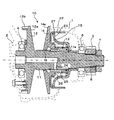
図1は、本例のベルト式無段変速機における第2軸の部分の断面図である。なお、無段変速機の全体構成については、前述の特許文献等に開示された公知例と同様でよい。
図1において、符号1がケーシング、符号2がサイドカバー、符号A2が第2軸、符号3が出力ギア、符号4,5が従動プーリの軸受(第2軸の軸受)、符号10が従動プーリ(セカンダリプーリ)を示す。
Hereinafter, an embodiment of the present invention will be described with reference to FIG.
FIG. 1 is a sectional view of a portion of a second shaft in the belt type continuously variable transmission of this example. The overall configuration of the continuously variable transmission may be the same as the known examples disclosed in the above-mentioned patent documents.
In FIG. 1, reference numeral 1 is a casing, reference numeral 2 is a side cover, reference numeral A2 is a second shaft, reference numeral 3 is an output gear, reference numerals 4 and 5 are driven pulley bearings (second shaft bearings), and
本例のベルト式無段変速機は、図示省略しているが、エンジンの出力軸と同軸の第1軸に配置されて、前記出力軸の回転を伝動する伝動装置(例えば、トルクコンバータ)と、第1軸における前記伝動装置に対してエンジンと反対側に配置されて、前記伝動装置の出力により駆動される駆動プーリと、第1軸と平行な第2軸A2に配置されて、前記駆動プーリとベルトにより連結される従動プーリ10と、第2軸A2における従動プーリ10に対してエンジン側に配置されて、従動プーリ10と一体に回転する出力ギア3と、第2軸A2と平行な第3軸に配置されて、前記出力ギア3とかみ合うアイドラギアと、前記第3軸に配置されて、前記アイドラギアと一体に回転するファイナルドライブギアと、前記第3軸と平行な第4軸に配置されて、前記ファイナルドライブギアに駆動される差動機構とを、筐体内に備える。
そして前記筐体が、ケーシング1と、このケーシング1のエンジン側に取り付けられるハウジング(図示省略)と、ケーシング1のエンジンと反対側に取り付けられるサイドカバー2とによって構成されている。
なお通常、例えば第1軸の伝動装置と駆動プーリの間の位置には、前後進切換機構が設けられる。
Although not shown, the belt-type continuously variable transmission of this example is disposed on a first shaft that is coaxial with the output shaft of the engine, and a transmission device (for example, a torque converter) that transmits the rotation of the output shaft; The drive pulley disposed on the opposite side of the engine to the transmission on the first shaft and driven by the output of the transmission, and the second shaft A2 parallel to the first shaft A driven
The casing includes a casing 1, a housing (not shown) attached to the engine side of the casing 1, and a side cover 2 attached to the opposite side of the casing 1 from the engine.
Normally, for example, a forward / reverse switching mechanism is provided at a position between the transmission device of the first shaft and the drive pulley.
従動プーリ10を含むプーリ構造は、この場合、図1に示す構成となっている。
即ち、回転軸11と、この回転軸11の一端側(図中左側)外周に固定状態(図では一体)に設けられた固定プーリ12(固定フランジ)と、回転軸11の他端側(図中右側)外周に固定プーリ12とシーブ面が対向するように配置され、回転軸11に対してボール等のスプライン13により回転を規制されて連結されて軸方向に摺動可能とされた可動プーリ14(可動フランジ)と、この可動プーリ14の背面側(図中右側)に形成された可動プーリ駆動用の作動液室15とを備え、可動プーリ14のシーブ面側(図中左側)内周面と、このシーブ面側内周面と対向する回転軸11の外周面との間の微小な隙間が、作動液室15のシール部16とされた構成となっていた。
In this case, the pulley structure including the driven
That is, the rotating shaft 11, a fixed pulley 12 (fixed flange) provided in a fixed state (integrated in the drawing) on the outer periphery of one end side (left side in the figure) of the rotating shaft 11, and the other end side (see FIG. (Middle right) A movable pulley that is arranged on the outer periphery so that the
可動プーリ14の背面には、筒状のシリンダ外周部材22が固定され、このシリンダ外周部材22の内側にはシリンダ壁部材23が摺動可能に装着されている。シリンダ壁部材23の内周部は、回転軸11の第1段部11aと、この内周部よりも他端側に装着された軸受5との間に挟みつけられた状態で、回転軸11に取付けられている。そして、前述した作動液室15は、上記シリンダ外周部材12及びシリンダ壁部材13と回転軸11の外周面などで囲まれる空間として形成されており、回転軸11の内部に形成された流路24と、可動プーリ14に形成された流路25とを経由して、作動液(通常は油)が室内全体に供給される構成となっている。また、作動液室15内(可動プーリ14とシリンダ壁部材23との間)には、スプリング26(この場合コイル状の圧縮バネ)が装填され、可動プーリ14が固定プーリ12に近づく向き(図中左方)に付勢されている。
A cylindrical cylinder outer
また、シリンダ壁部材23の外周には、シール部材27が取付けられ、シリンダ壁部材23の外周とシリンダ外周部材22の内周との間(摺動面間)がシールされている。
なお、出力ギア3は、軸受5の隣(図中右側)に配置され、回転軸11に対してスプライン6により連結されている。そして、前述したシリンダ壁部材23の内周部、軸受5の内輪、及び出力ギア3は、回転軸11の他端部(図中右端)外周にねじ込まれるナット7によって、前述の第1段部11aに対して押し付けられるようにして回転軸11に固定されている。
Further, a
The output gear 3 is disposed next to the bearing 5 (right side in the figure) and is connected to the rotary shaft 11 by a
ここで、作動液室15に作動液が供給され、この作動液の圧力とスプリング26の付勢力が、ベルトからの反力等を上回ると、可動プーリ14が固定プーリ12の側(図中左側)に押されて、可動プーリ14と固定プーリ12のシーブ面14a,12a(傾斜面)の間隔が狭くなり、ここに巻かれたVベルトの有効半径が大きくなる。逆に、作動液の圧力等がベルトからの反力等を下回ると、可動プーリ14が反対側(図中右側)に押されて、可動プーリ14と固定プーリ12のシーブ面14a,12aの間隔が広がり、ここに巻かれたVベルトの有効半径が小さくなる。このため、このようなプーリ構造が入力側と出力側に設けられることで、無段変速が可能となる。
Here, when the hydraulic fluid is supplied to the
次に、固定プーリ12(固定フランジ)の外周には、パーキングギアとしての歯12bが形成されており、ここに図示省略したパーキングポールの歯が係合してパーキング時の回転ロックが実現される構成となっている。即ち、パーキングポールは、非パーキング状態(車両のセレクトレバーがパーキング位置に操作されていない状態)では、パーキングギアの歯12bから離れたロック解除位置に保持される。ところが、セレクトレバーがパーキング位置に操作されたパーキング状態になると、図示省略したパーキング機構の作用により、パーキングポールの係合部がパーキングギアの歯12bにかみ合うロック位置に揺動して保持される。
Next,
そして、固定プーリ12(固定フランジ)の外周に形成されたパーキングギアとしての歯12bは、この場合固定プーリ12の隣(図中左側)に配置された、回転軸11の一方の軸受4と、軸方向において略同一位置に設けられている。即ち、図1に示すように、固定プーリ12の外周は、軸受4の外周側に伸びる円筒状の形状とされており、この円筒状部分にパーキングギアとしての歯12bが形成されている。このため、パーキングギアとしての歯12bと軸受4は、略同一径上に位置している。
And the
以上説明した本例のベルト式無段変速機によれば、従動プーリ10の固定フランジ外周(固定プーリ12の外周)にパーキングギアを設けているため、部品が共用されて前述の問題(パーキングギアの分だけ部品点数が増加し大型化する問題)が解消される。
しかも、上述したようにパーキングギアの歯12bと従動プーリの軸受4との位置関係が設定されているため、パーキング時にパーキングギアに加わる力が上記軸受4,5にモーメントとして加わる大きさは、ゼロか極めて僅かなものとなり、上記軸受4,5の耐久性確保も格段に容易となる。
According to the belt-type continuously variable transmission of the present example described above, the parking gear is provided on the outer periphery of the fixed flange of the driven pulley 10 (the outer periphery of the fixed pulley 12). The problem of the increase in the number of parts and the increase in size) is solved.
Moreover, since the positional relationship between the
なお、本発明は上述した形態例に限られず、各種の変形や応用があり得る。
例えば、上記形態例では、軸受4の外周の一部にパーキングギアの歯12bが重なる態様(軸受4と歯12bの一部分の軸方向位置が一致する態様)としたが、例えば軸方向における軸受4と歯12bの中心位置が完全に一致するように設けてもよい。
また本発明は、作動液室の構成や出力ギアの取付構造などの点においても、上記形態例に限定されないことは、いうまでもない。
The present invention is not limited to the above-described embodiments, and various modifications and applications are possible.
For example, in the above embodiment, the
Needless to say, the present invention is not limited to the above-described embodiment in terms of the configuration of the hydraulic fluid chamber and the output gear mounting structure.
1 ケーシング
2 サイドカバー
4,5 軸受
12 従動プーリ
12b パーキングギアの歯
1 Casing 2 Side cover 4,5
Claims (1)
前記従動プーリの固定フランジ外周にパーキングギアを設けるとともに、このパーキングギアの歯と前記従動プーリの軸受とを、前記第2軸の軸方向における同一位置に配置したことを特徴とするベルト式無段変速機。 A transmission device disposed on a first shaft coaxial with an output shaft of the engine and configured to transmit rotation of the output shaft; and a transmission device disposed on a side opposite to the engine with respect to the transmission device on the first shaft. A drive pulley driven by the output of the motor, a driven pulley arranged on a second shaft parallel to the first shaft and connected by the drive pulley and a belt, and an engine with respect to the driven pulley on the second shaft In a belt-type continuously variable transmission that is disposed on the side and includes an output gear that rotates integrally with the driven pulley,
A belt-type continuously variable motor, wherein a parking gear is provided on the outer periphery of the fixed flange of the driven pulley, and the teeth of the parking gear and the bearing of the driven pulley are arranged at the same position in the axial direction of the second shaft. transmission.
Priority Applications (4)
| Application Number | Priority Date | Filing Date | Title |
|---|---|---|---|
| JP2004105777A JP2005291319A (en) | 2004-03-31 | 2004-03-31 | Belt type continuously variable transmission |
| KR1020040102722A KR100692337B1 (en) | 2004-03-31 | 2004-12-08 | Beltless CVT |
| EP05006271A EP1582768A3 (en) | 2004-03-31 | 2005-03-22 | Belt type continuously variable transmission |
| US11/086,408 US20050233847A1 (en) | 2004-03-31 | 2005-03-23 | Belt type continuously variable transmission |
Applications Claiming Priority (1)
| Application Number | Priority Date | Filing Date | Title |
|---|---|---|---|
| JP2004105777A JP2005291319A (en) | 2004-03-31 | 2004-03-31 | Belt type continuously variable transmission |
Publications (2)
| Publication Number | Publication Date |
|---|---|
| JP2005291319A true JP2005291319A (en) | 2005-10-20 |
| JP2005291319A5 JP2005291319A5 (en) | 2006-07-13 |
Family
ID=34880077
Family Applications (1)
| Application Number | Title | Priority Date | Filing Date |
|---|---|---|---|
| JP2004105777A Pending JP2005291319A (en) | 2004-03-31 | 2004-03-31 | Belt type continuously variable transmission |
Country Status (4)
| Country | Link |
|---|---|
| US (1) | US20050233847A1 (en) |
| EP (1) | EP1582768A3 (en) |
| JP (1) | JP2005291319A (en) |
| KR (1) | KR100692337B1 (en) |
Cited By (2)
| Publication number | Priority date | Publication date | Assignee | Title |
|---|---|---|---|---|
| US8864610B2 (en) | 2010-03-04 | 2014-10-21 | Toyota Jidosha Kabushiki Kaisha | Belt type continuously variable transmission for vehicle |
| US8888617B2 (en) | 2010-05-26 | 2014-11-18 | Toyota Jidosha Kabushiki Kaisha | Belt type continuously variable transmission |
Families Citing this family (5)
| Publication number | Priority date | Publication date | Assignee | Title |
|---|---|---|---|---|
| JP2006103398A (en) * | 2004-10-01 | 2006-04-20 | Jatco Ltd | Parking mechanism |
| DE102005026616A1 (en) * | 2005-06-09 | 2006-12-14 | Zf Friedrichshafen Ag | Continuously variable automatic transmission unit, comprising lid integrated in converter housing and secured from outside |
| CN102859235B (en) * | 2009-09-15 | 2016-02-24 | 研究业务流程重组财团-舍布鲁克大学法律部 | For the driving pulley of stepless speed variator |
| DE102015223014B4 (en) * | 2015-11-23 | 2017-08-10 | Schaeffler Technologies AG & Co. KG | Arrangement for the axial clamping of a CVT fixed bearing from outside a transmission housing |
| JP7554302B2 (en) * | 2023-02-28 | 2024-09-19 | 本田技研工業株式会社 | Continuously variable transmission |
Family Cites Families (12)
| Publication number | Priority date | Publication date | Assignee | Title |
|---|---|---|---|---|
| JPS57137757A (en) * | 1981-02-16 | 1982-08-25 | Aisin Warner Ltd | Controller for fluid pressure of belt type stepless change gear |
| JPS60161012A (en) * | 1984-01-31 | 1985-08-22 | Fuji Heavy Ind Ltd | Cutting method forming plural cuts on peripheral surface of disk |
| US4999283A (en) * | 1986-01-10 | 1991-03-12 | University Of Kentucky Research Foundation | Method for x and y spermatozoa separation |
| JPH01295067A (en) * | 1988-05-19 | 1989-11-28 | Mazda Motor Corp | Hydraulic control device for continuously variable transmission |
| JPH01283463A (en) * | 1989-03-24 | 1989-11-15 | Aisin Aw Co Ltd | Belt type continuously variable automatic transmission for vehicle |
| DE4407145A1 (en) * | 1994-03-04 | 1995-09-07 | Zahnradfabrik Friedrichshafen | Device for supporting elements in a continuously variable belt transmission |
| JP3306217B2 (en) * | 1994-04-04 | 2002-07-24 | 愛知機械工業株式会社 | Parking mechanism for continuously variable transmission |
| JP4096370B2 (en) * | 1997-01-16 | 2008-06-04 | アイシン・エィ・ダブリュ株式会社 | Continuously variable transmission |
| DE19857710B4 (en) * | 1997-12-22 | 2013-02-21 | Schaeffler Technologies AG & Co. KG | transmission |
| DE19909347B4 (en) * | 1998-03-10 | 2012-03-29 | Schaeffler Technologies Gmbh & Co. Kg | transmission |
| JP2939226B1 (en) * | 1998-03-17 | 1999-08-25 | 三菱製鋼株式会社 | Method of forming pulley shaft with parking gear |
| JP2000104827A (en) * | 1998-09-30 | 2000-04-11 | Fuji Heavy Ind Ltd | Parking device for continuously variable transmission |
-
2004
- 2004-03-31 JP JP2004105777A patent/JP2005291319A/en active Pending
- 2004-12-08 KR KR1020040102722A patent/KR100692337B1/en not_active Expired - Fee Related
-
2005
- 2005-03-22 EP EP05006271A patent/EP1582768A3/en not_active Ceased
- 2005-03-23 US US11/086,408 patent/US20050233847A1/en not_active Abandoned
Cited By (2)
| Publication number | Priority date | Publication date | Assignee | Title |
|---|---|---|---|---|
| US8864610B2 (en) | 2010-03-04 | 2014-10-21 | Toyota Jidosha Kabushiki Kaisha | Belt type continuously variable transmission for vehicle |
| US8888617B2 (en) | 2010-05-26 | 2014-11-18 | Toyota Jidosha Kabushiki Kaisha | Belt type continuously variable transmission |
Also Published As
| Publication number | Publication date |
|---|---|
| KR20050096828A (en) | 2005-10-06 |
| KR100692337B1 (en) | 2007-03-13 |
| EP1582768A3 (en) | 2006-08-16 |
| EP1582768A2 (en) | 2005-10-05 |
| US20050233847A1 (en) | 2005-10-20 |
Similar Documents
| Publication | Publication Date | Title |
|---|---|---|
| US8967350B2 (en) | Driving force transmission apparatus | |
| US8414433B2 (en) | Continuously variable transmission | |
| US6612961B2 (en) | Forward-reverse rotation device for a continuously variable transmission | |
| CN114144598A (en) | Clutch device | |
| CN114144596A (en) | Clutch device | |
| CN114144595A (en) | Clutch device | |
| CN106051104B (en) | Transmission device with the pinion gear for reduced backlash | |
| US9689440B2 (en) | Power transfer device | |
| JP2019158055A (en) | Automatic transmission | |
| US6824494B2 (en) | Planetary gear unit | |
| EP1326035A2 (en) | Low noice gear assembly | |
| JP6206298B2 (en) | Clutch device | |
| US8109377B2 (en) | Clutch device | |
| JP2005291319A (en) | Belt type continuously variable transmission | |
| EP3467351B1 (en) | Cap with helical lsd clutch | |
| JP6454558B2 (en) | Friction engagement device | |
| JP2007139142A (en) | Automatic transmission | |
| JP2005291317A (en) | Pulley structure | |
| US9347547B2 (en) | Transmission | |
| JP2007303494A (en) | Differential device | |
| JP5371700B2 (en) | Differential device | |
| JPH10274320A (en) | Belt type transmission for vehicles | |
| JP2009103166A (en) | Belt type continuously variable transmission | |
| JP2004060702A (en) | Shaft support structure for continuously variable transmission | |
| JP2007298139A (en) | Belt type continuously variable transmission |
Legal Events
| Date | Code | Title | Description |
|---|---|---|---|
| A621 | Written request for application examination |
Free format text: JAPANESE INTERMEDIATE CODE: A621 Effective date: 20050818 |
|
| A521 | Written amendment |
Free format text: JAPANESE INTERMEDIATE CODE: A523 Effective date: 20060529 |
|
| A131 | Notification of reasons for refusal |
Free format text: JAPANESE INTERMEDIATE CODE: A131 Effective date: 20071226 |
|
| A977 | Report on retrieval |
Free format text: JAPANESE INTERMEDIATE CODE: A971007 Effective date: 20071228 |
|
| A02 | Decision of refusal |
Free format text: JAPANESE INTERMEDIATE CODE: A02 Effective date: 20080702 |