JP2009103166A - Belt type continuously variable transmission - Google Patents
Belt type continuously variable transmission Download PDFInfo
- Publication number
- JP2009103166A JP2009103166A JP2007273726A JP2007273726A JP2009103166A JP 2009103166 A JP2009103166 A JP 2009103166A JP 2007273726 A JP2007273726 A JP 2007273726A JP 2007273726 A JP2007273726 A JP 2007273726A JP 2009103166 A JP2009103166 A JP 2009103166A
- Authority
- JP
- Japan
- Prior art keywords
- movable pulley
- pulley
- flat plate
- continuously variable
- shaft
- Prior art date
- Legal status (The legal status is an assumption and is not a legal conclusion. Google has not performed a legal analysis and makes no representation as to the accuracy of the status listed.)
- Pending
Links
Images


Abstract
Description
本発明は、ベルト式無段変速機に関し、特に、固定プーリと可動プーリとの摺動構造に関するものである。 The present invention relates to a belt type continuously variable transmission, and more particularly to a sliding structure between a fixed pulley and a movable pulley.
ベルト式無段変速機は、金属製のベルトを介して入力側から出力側への動力伝達を行う。このベルト式無段変速機は、固定プーリに対して、可動プーリを軸方向に摺動させて移動させることによりベルトの有効半径を変化させて、変速比を変更する。 The belt type continuously variable transmission transmits power from the input side to the output side via a metal belt. This belt-type continuously variable transmission changes the gear ratio by changing the effective radius of the belt by sliding and moving the movable pulley in the axial direction with respect to the fixed pulley.
このようなベルト式無段変速機では、トルクの方向が切り替わる場合に、固定プーリに対して可動プーリが相対回転を起こすと、ベルトを構成する駒が回転方向に変位して金属製のベルトが破損してしまう場合がある。そのため、固定プーリと可動プーリとの相対回転を防止するためにこれらを精度良く管理する必要がある。 In such a belt type continuously variable transmission, when the direction of torque is switched, if the movable pulley causes relative rotation with respect to the fixed pulley, the pieces constituting the belt are displaced in the rotation direction, and the metal belt is moved. It may be damaged. Therefore, it is necessary to manage these with high accuracy in order to prevent relative rotation between the fixed pulley and the movable pulley.
従来このような固定プーリと可動プーリとの摺動構造に関して、特許文献1には、ボールスプラインによって固定プーリと可動プーリとを嵌め合わせるプーリ構造が記載されている。
Conventionally, regarding such a sliding structure between a fixed pulley and a movable pulley,
また、特許文献2には、ローラスプラインによって固定プーリと可動プーリとを摺動自在に配置する無段変速機が記載されている。 Patent Document 2 describes a continuously variable transmission in which a fixed pulley and a movable pulley are slidably arranged by roller splines.
また、特許文献3には、互いにスプライン歯が形成された可動シーブと固定シーブとが嵌合されているベルト式無段変速機が記載されている。
しかしながら、特許文献1に記載のようなボールスプラインを用いた場合は、部品点数が多くなり、また、スプライン溝の加工精度が要求される。さらに、ボールを固定するためのスナップリングを組付ける際の作業時間がかかる等、コストが上昇してしまうといった問題がある。また、大きなトルクを受け持つために、ボールの数が増え、固定プーリ及び可動プーリの軸方向の長さが大きくなってしまう。
However, when a ball spline as described in
また、前述の特許文献2に記載のようなローラを用いた場合は、ボールスプラインと同様に、スプライン溝の加工精度が要求される。また、ローラを固定するためのスナップリング等の組付けによる作業時間がかかる等、コストが上昇してしまう。さらに、軸方向の突け当て面の面圧が高くなるため、ローラの端部接触面の硬度を高くする必要があり、やはりコストが上昇してしまう。 In addition, when a roller as described in Patent Document 2 is used, the processing accuracy of the spline groove is required as in the case of the ball spline. In addition, the cost increases, for example, it takes time to assemble a snap ring or the like for fixing the roller. Furthermore, since the surface pressure of the abutting surface in the axial direction becomes high, it is necessary to increase the hardness of the end contact surface of the roller, which also increases the cost.
また、前述の特許文献3に記載のような双方スプラインを用いた場合は、スプライン歯を転造により作成するために、固定プーリと回転プーリとの公差により回転ガタが大きくなり、使用できるベルトに制限がある。 In addition, when both splines as described in the above-mentioned Patent Document 3 are used, since the spline teeth are formed by rolling, the rotation play is increased due to the tolerance between the fixed pulley and the rotating pulley, and the belt can be used. There is a limit.
本発明は、このような問題点に着目してなされたものであり、部品点数を増加させることなく、回転ズレを防止できると共に、回転軸の軸方向の長さを短縮して、より小型化が可能となるベルト式無段変速機を提供することを目的とする。 The present invention has been made by paying attention to such problems, and can prevent rotational displacement without increasing the number of parts, and reduce the axial length of the rotating shaft, thereby further reducing the size. It is an object of the present invention to provide a belt-type continuously variable transmission that can be used.
本発明の一実施態様によると、固定プーリ15aを有する回転軸13と、回転軸13の外周に配置され、回転軸13の軸方向に摺動可能に勘合された可動プーリ15bと、回転軸13に設けられた第1の平面部101aと、可動プーリ15bの内周に設けられた第2の平面部101bと、第1の平面部101aと第2の平面部101bとの間に介在する平板110と、を備え、平板110によって、固定プーリ15aと可動プーリ15bとを回転不能に支持し、平板110の軸方向への移動を係止する突当部102を、回転軸13に設けたことを特徴とする。
According to one embodiment of the present invention, the rotating
本発明によると、回転軸に固定状態に設けられた固定プーリの回転トルクを、第1の平面部と第2の平面部との間に介在する平板により可動プーリに伝えるので、部品点数を増やすことなく固定プーリと可動プーリとの回転ズレを精度良く管理できると共に、トルクを受け持つ面積を広くとることができ、回転軸の軸方向の長さを縮小でき、ベルト式無段変速機を小型化することが可能となる。 According to the present invention, the rotational torque of the fixed pulley provided in a fixed state on the rotating shaft is transmitted to the movable pulley by the flat plate interposed between the first flat surface portion and the second flat surface portion, thereby increasing the number of parts. It is possible to manage the rotational deviation between the fixed pulley and the movable pulley with high accuracy, and to increase the area for torque, reduce the axial length of the rotating shaft, and reduce the size of the belt type continuously variable transmission. It becomes possible to do.
以下に、本発明の実施の形態のベルト式無段変速機について、図面を用いて説明する。 Hereinafter, a belt type continuously variable transmission according to an embodiment of the present invention will be described with reference to the drawings.
図1は、本実施形態のベルト式無段変速機(CVT)の構成の一例を示す正面断面図である。 FIG. 1 is a front sectional view showing an example of the configuration of a belt type continuously variable transmission (CVT) according to the present embodiment.
図示しないエンジンにより駆動される出力軸1の回転は、無段変速機のケース9に内装される発進装置としてのトルクコンバータ2と、前後進切換機構3と、無段変速機構4とに伝達される。
The rotation of the
トルクコンバータ2は、所謂ロックアップを制御するロックアップクラッチ5を備えており、ロックアップクラッチ5は、タービン軸6に連結されている。ロックアップクラッチ5の一方側は、供給室(以下、アプライ室)7a、他方側は開放室(以下、リリース室)7bとして形成される。リリース室7b内に供給した油圧をアプライ室7aを介して循環させることによりトルクコンバータ2は作動状態となる。一方、アプライ室7aに油圧を供給し、リリース室7b内の油圧を下げることによりロックアップクラッチ5は、フロントカバー8と係合してロックアップ状態となる。このリリース室7b内の圧力を調整することによりロックアップクラッチ5を意図的に滑らせるようにしたスリップ圧制御が行われる。
The torque converter 2 includes a
前後進切換機構3は、トルクコンバータ2の出力軸であるタービン軸6の回転を無段変速機構4に正(前進)方向に伝達するための前進用クラッチと、逆(後退)方向に伝達するための後退用ブレーキとを備えている。クラッチ油室に油圧を供給して前進用クラッチを接続状態とすると、タービン軸6の回転は無段変速機構4に正方向に伝達され、ブレーキ油室に油圧を供給して後退用ブレーキを接続状態とすると、逆方向に減速して伝達される。
The forward / reverse switching mechanism 3 transmits the rotation of the turbine shaft 6 that is the output shaft of the torque converter 2 to the continuously
無段変速機構4は、前後進切換機構3に連結される入力軸(プライマリ軸)13と、これと平行に配置された出力軸(セカンダリ軸)14とを備えている。
The continuously
プライマリ軸13にはプライマリプーリ15が設けられている。プライマリプーリ15は、プライマリ軸13の外周に固定状態に設けられた固定プーリ15aと、プライマリ軸13の外周に配置され、軸方向に摺動可能に嵌合される可動プーリ15bとを有する。固定プーリ15aに対して可動プーリ15bが摺動されることにより、プーリのベルト17が接触するプーリ面の間隔、つまりプーリ溝幅が可変に形成される。
A
固定プーリ15a及び可動プーリ15bは、それぞれが向かい合う面に、円周状の平面部により形成される固定シーブ面15c及び可動シーブ面15dを備える。
The fixed
セカンダリ軸14にはセカンダリプーリ16が設けられている。セカンダリプーリ16は、セカンダリ軸14の外周に固定状態に設けられた固定プーリ16aと、セカンダリ軸14の外周に配置され、軸方向に摺動可能に嵌合される可動プーリ16bとを有する。固定プーリ16aに対して可動プーリ16bが摺動されることにより、プーリ溝幅が可変に形成される。
A
なお、固定プーリ16a及び可動プーリ16bは、それぞれが向かい合う面に、円周状の平面部により形成される固定シーブ面16c及び可動シーブ面16dを備える。
The fixed
これら固定プーリ15a及び可動プーリ15b又は固定プーリ16a及び可動プーリ16bは、図2において後述する摺動構造により、摺動可能に構成されている。
The
プライマリプーリ15とセカンダリプーリ16との間には、ベルト17が掛け渡されている。これら両方のプーリ15、16の溝幅を変化させて、それぞれのプーリ15、16に対する巻付け径の比率を変化させることにより、プライマリ軸13の回転がセカンダリ軸14に無段階に変速されて伝達されることになる。
A
セカンダリ軸14の回転は、減速歯車及びディファレンシャル装置18を有する歯車列を介して車輪に伝達されるようになっている。なお、前輪駆動車の場合には、車輪は前輪となる。
The rotation of the
次に、プライマリプーリ15及びセカンダリプーリ16の周辺の構成をさらに詳しく説明する。
Next, the configuration around the
プライマリプーリ15の溝幅を変化させるために、プライマリ軸13には、円筒部とディスク部とを有するプランジャ隔壁21が固定され、このプランジャ隔壁21の外周側端部に摺動可能に接触するプライマリシリンダ22が、可動プーリ15bのプーリ面のプライマリ軸方向背面側に固定されており、プランジャ隔壁21とプライマリシリンダ22(可動プーリ15b)との間には、作動油室23aが形成されている。一方、プライマリシリンダ22の開口端側内面にはプライマリ軸方向に延出する円盤状のプレート(隔壁)24が固定され、このプレート24とプランジャ隔壁21との間に、バランス油室23bが形成されている。従って、バランス油室23bはプランジャ隔壁21を挟んで作動油室23aと対向して設けられる。
In order to change the groove width of the
セカンダリプーリ16の溝幅を変化させるために、セカンダリ軸14にはテーパー状の円筒部を有するプランジャ隔壁26が固定され、このプランジャ隔壁26の外周面に摺動可能に接触するセカンダリシリンダ27が、可動プーリ16bのプーリ面のセカンダリ軸方向背面側に固定されており、プランジャ隔壁26とセカンダリシリンダ27(可動プーリ16b)との間には作動油室28aが形成されている。一方、セカンダリシリンダ27の開口端内側にはセカンダリ軸方向に延出する円盤状のプレート29が設けられ、このプレート29とプランジャ隔壁26との間にはバランス油室28bが形成されている。
In order to change the groove width of the
従って、プライマリシリンダ22内の作動油室23a内に作動油を供給してその容積を大きくすると、可動プーリ15bはプライマリシリンダ22とともに固定プーリ15a側に移動してプーリ溝幅が狭くなり、容積を小さくするとプーリ溝幅が広くなる。また、セカンダリシリンダ27内の作動油室28a内に作動油を供給してその容積を大きくする可動プーリ16bは、セカンダリシリンダ27とともに固定プーリ16a側に移動してプーリ溝幅が狭くなり、容積を小さくするとプーリ溝幅が広くなる。
Accordingly, when the hydraulic oil is supplied into the
ケース9は、プライマリ軸13の一端をベアリングを介して回転自在に支持するサイドカバー9aを備え、このサイドカバー9aに作動油が流通する油路10が配置される。ここで、ケース9は、前後進切換機構3と無段変速機構4を内装する円筒状のケース本体9bと、このケース本体9bの開口部を閉塞するサイドカバー9aと、ケース本体9bのエンジン側に固定され、トルクコンバータ2を内装するコンバータハウジング9cとから構成される。
The case 9 includes a
CVTが作動しているときには、作動油室23a内の作動油にはプライマリプーリ15の回転によって遠心力に起因する油圧が発生し、その遠心油圧は可動プーリ15bをベルト17に押し付ける方向に作用するが、この方向とは逆方向の遠心油圧がバランス油室23bに発生する。同様に、作動油室28aにはセカンダリプーリ16の回転によって遠心油圧が発生するが、この方向とは逆方向の遠心油圧がバランス油室28bに発生する。このようにして、作動油室23a、28aに生じる遠心油圧がバランス油室23b、28bに生じる遠心油圧により相殺されて、遠心油圧によるプライマリプーリ15、セカンダリプーリ16の溝幅の変化が抑制できる。
When the CVT is operating, the hydraulic oil in the
次に、本実施の形態の固定プーリ15a及び可動プーリ15bの摺動構造を、より詳細に説明する。
Next, the sliding structure of the fixed
なお、以降はプライマリプーリ15を例に説明するが、セカンダリプーリ16の構成についても同様である。
Hereinafter, the
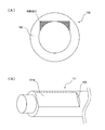
図2は、固定プーリ15a及び可動プーリ15bの断面図である。なお、図2(a)はプライマリプーリ15の断面図、図2(B)は図2(A)のA−A断面図である。
FIG. 2 is a cross-sectional view of the fixed
前述のように固定プーリ15aと可動プーリ15bとは、プライマリ軸13の軸方向に摺動可能に構成される。
As described above, the fixed
ここで、固定プーリ15aに対して可動プーリ15bが周方向に相対回転した場合には、ベルト17を構成する駒が回転方向に変位し、ベルト17を構成する金属製のベルトが破損してしまう場合がある。そのため、固定プーリと可動プーリとの相対回転を防止するためにこれらを精度良く管理する必要がある。
Here, when the
そこで、本実施の形態では、この図2に示すような特徴的な構成を備えた。すなわち、固定プーリ15aと可動プーリ15bとの間に、平板110を介在した摺動構造により、摺動可能に構成されている。
Therefore, the present embodiment has a characteristic configuration as shown in FIG. That is, it is configured to be slidable by a sliding structure in which the
具体的には、固定プーリ15aには、プライマリ軸13の外周面に略平面を有する平面部101aが形成されている。そして、この平面部101aに対して略垂直の立設面を有する突当部102が、平面部101aの固定プーリ15a側に形成されている。
Specifically, the fixed
可動プーリ15bは、プライマリ軸13を外周で囲繞する可動プーリ軸部150を備える。この可動プーリ軸部150には、固定プーリ15a側の平面部101aと略並行に、略平面を有する平面部101bが形成されている。
The
そして、この平面部101aと平面部101bとの間に、平板110が狭持される。
And the
平板110は、直方体形状を有しており、平面部101aに対峙する面と、平面部101bに対峙する面とが略並行に形成されている。この平板110は、プライマリ軸13の軸方向に関して、一方がプランジャ隔壁21に接触させて、プランジャ隔壁21よりその動きが規制される。他方が突当部102に接触させて、突当部102によりその動きが規制されている。すなわち、平板110は、プランジャ隔壁21と突当部102とに狭持されて軸方向への移動が係止されている。言い換えると、平板110は、固定プーリ15aに固定され、可動プーリ15bに対して摺動可能に構成されている。
The
なお、プライマリ軸13において、平板110は、軸中心から近い(すなわち面圧が高い)平面部101aではなく、軸中心から離れている(すなわち面圧が低い)平面部101bで摺動可能に構成されている。このように構成することにより、平板110の要求高度を低くすることができる。
In the
図2(B)に示すように、平面部101aと、平面部101bとによって狭持された平板110によって、固定プーリ15aの回転トルクが可動プーリ15bに伝達される。
As shown in FIG. 2B, the rotational torque of the fixed
特に、固定プーリ15a側の平面部101a、可動プーリ15b側の平面部10b及び平板110は、全て略平面によって構成されるため、ボールやローラ等のような点や線で接する構成よりも、トルクを受け持つ面積が大きくなると共に、加工精度を高めることにより回転ガタの発生を小さく管理することができる。
In particular, since the
回転ガタを精度よく管理することができる。 Rotational play can be managed accurately.
なお、図2(B)において、平板110の左右には若干の空間が示されているが、これは、トルクを受け持たない部分である平板110の左右部分は、可動プーリ軸部150の内壁の左右立設部に接触させる必要がないことを示す。
2B, a slight space is shown on the left and right sides of the
すなわち、固定プーリ15aの回転トルクを可動プーリ15bへと伝えるのは平面部101aと平面部101bとに狭持された平板110の上下面のみである。これらの各面は回転ガタが発生しないように加工精度を高く管理する必要がある。すなわち、平板110の厚み方向の加工精度を高く管理する必要がある。
That is, only the upper and lower surfaces of the
一方、平板110の左右面及び、軸方向に並行かつ平面部101bに対して垂直に形成された左右立設部は、回転トルクを受け持たないため、予め所定の間隙を隔てるように加工する。すなわち、平板110の左右の大きさが、平面部101bの左右立設部よりも小さくなるように加工する。この左右方向の大きさ加工精度の高さが要求されないため、平面部101a及び101bに対峙する面と左右立設部とを含めた四辺の加工精度を高く管理するよりも加工コストを低く抑えることができる。
On the other hand, the left and right surfaces of the
なお、プーリ組立ての際の作業性を考慮して、可動プーリ15bの可動プーリ軸部150の平面部101bの端部(図2(A)においてXで示す部分)に、面取りやR面等の加工を施すと、組立て性の向上のために好適である。
In consideration of workability at the time of pulley assembly, chamfering, R surface, etc. are provided at the end of the
図3は、固定プーリ15a及び可動プーリ15bの加工方法の説明図である。なお、図3(A)は、可動プーリ15bの可動プーリ軸部150の加工方法の説明図であり、図3(B)は、固定プーリ15a側のプライマリ軸13の加工方法の説明図である。
FIG. 3 is an explanatory diagram of a method for processing the fixed
可動プーリ15bにおいて、可動プーリ軸部150は、中空円筒状に予め加工されている。これに対して、例えばブローチ加工により、可動プーリ軸部150の内面に略矩形の形状を切削加工することによって、平面部101bが形成される。
In the
また、図3(B)に示すように、プライマリ軸13に、略平面及び立設面を切削加工することによって、平面部101a及び突当部102が形成される。
Further, as shown in FIG. 3B, the
以上のように構成された本発明の実施の形態について、次に効果を説明する。 Next, effects of the embodiment of the present invention configured as described above will be described.
本発明の実施の形態では、固定プーリ15aと可動プーリ15bと狭持される平板110を備えた。このように構成することによって、スプライン加工よりも加工が容易な平面部のみによって、固定プーリ15a及び可動プーリ15bを構成することができ、加工コストを小さくすることが可能となる。
In the embodiment of the present invention, the
また、平板110を、固定プーリ15a側の平面部101aと、可動プーリ15b側の平面部101bとによって狭持するように構成したので、スプライン加工によるボール軸受やローラ軸受等と比較して、平面部の加工精度を高くすることができる。また、ボールやローラ等で必要となる外れ防止のためのピンやリング等が不要となる。従って、固定プーリ15aと可動プーリ15bとの回転ガタを、高い精度で管理することが可能となると共に、加工コスト及び組立てコストを低く抑えることが可能となる。
Further, since the
また、平板110の板厚を変更することによって、固定プーリ15aと可動プーリ15bとのガタ量を容易に調整することが可能となる。例えば、異なる板厚の平板110を予め用意しておき、固定プーリ15aの平面部101aと可動プーリ15bの平面部101bとの間隔に応じて適切な板厚の平板110を選択することにより、回転ガタ量を精度良く管理することが可能となる。
Further, by changing the plate thickness of the
また、スプライン加工によるボール軸受やローラ軸受等と比較して、平板110は、回転トルクの負荷を受け持つ面積を大きくとることが可能となる。このため、平板110は、単位面積当たりにかかる面圧が小さくなるので、平板110、固定プーリ15aの平面部101a及び可動プーリ15bの平面部101bの面積を小さくすることができる。これにより、プライマリ軸13(またはセカンダリ軸14)の軸方向の長さを小さくすることが可能となり、その結果、ベルト式無段変速機を軸方向に小型化することが可能となる。
Further, as compared with a ball bearing or a roller bearing by spline processing, the
また、平板110は、単位面積当たりにかかる面圧が小さくなるので、平板110、固定プーリ15aの平面部101a及び可動プーリ15bの平面部101bの要求硬度を小さくすることができ、加工コストを小さくすることが可能となる。
Further, since the
なお、可動プーリ15bにおいて、可動プーリ15bの変速比が最大(可動プーリ15bがプランジャ隔壁21側に最も移動した状態)では、可動プーリ軸部150の端部は何処にも接触させない、又は、プランジャ隔壁21に接触させることが一般的である。これに対して、変速比が最大時に、可動プーリ軸部150の内周奥手側を平板110の端部に突き当たるように構成してもよい。このように構成することによって、余分な空間が少なくなり、プライマリ軸13(またはセカンダリ軸14)の軸方向の長さを小さくすることができる。なお、このように構成する場合は、平板110、プランジャ隔壁21、可動プーリ15b等の強度を高くする必要がある。
In the
本発明は上記した実施形態に限定されるものではなく、その技術的思想の範囲内でなしうるさまざまな変更、改良が含まれることは言うまでもない。 It goes without saying that the present invention is not limited to the above-described embodiments, and includes various modifications and improvements that can be made within the scope of the technical idea.
1 出力軸
2 トルクコンバータ
13 入力軸(プライマリ軸)
14 出力軸(セカンダリ軸)
15 プライマリプーリ
15a 固定プーリ
15b 可動プーリ
16 セカンダリプーリ
16a 固定プーリ
16b 可動プーリ
17 ベルト
21 プランジャ隔壁
26 プランジャ隔壁
101a 平面部
101b 平面部
102 突当部
110 平板
150 可動プーリ軸部
1 Output shaft 2
14 Output shaft (secondary shaft)
DESCRIPTION OF
Claims (6)
前記回転軸の外周に配置され、前記回転軸の軸方向に摺動可能に勘合された可動プーリと、
前記回転軸に設けられた第1の平面部と、
前記可動プーリの内周に設けられた第2の平面部と、
前記第1の平面部と前記第2の平面部との間に介在する平板と、
を備え、
前記平板によって、前記固定プーリと前記可動プーリとを回転不能に支持し、
前記平板の軸方向への移動を係止する突当部を、前記回転軸に設けたことを特徴とするベルト式無段変速機。 A rotating shaft having a fixed pulley;
A movable pulley disposed on the outer periphery of the rotary shaft and fitted so as to be slidable in the axial direction of the rotary shaft;
A first planar portion provided on the rotating shaft;
A second flat surface provided on the inner periphery of the movable pulley;
A flat plate interposed between the first plane portion and the second plane portion;
With
By the flat plate, the fixed pulley and the movable pulley are supported so as not to rotate,
A belt type continuously variable transmission characterized in that an abutting portion for locking the movement of the flat plate in the axial direction is provided on the rotating shaft.
前記第2の平面部は、前記可動プーリーの内周に、前記可動プーリの軸方向と並行に形成されることを特徴とする請求項1に記載のベルト式無段変速機。 The first plane portion is formed on the outer periphery of the rotating shaft from the end of the rotating shaft to the abutting portion in parallel with the axial direction,
2. The belt-type continuously variable transmission according to claim 1, wherein the second planar portion is formed on an inner periphery of the movable pulley in parallel with an axial direction of the movable pulley.
前記突当部と前記プランジャ部とにより、前記平板の軸方向への移動を係止することを特徴とする請求項1から3の何れか一つに記載のベルト式無段変速機。 A cylindrical portion and a disk portion provided in a fixed state on the rotating shaft, and a plunger portion that forms an oil chamber with the movable pulley,
The belt-type continuously variable transmission according to any one of claims 1 to 3, wherein movement of the flat plate in an axial direction is stopped by the abutting portion and the plunger portion.
前記可動プーリ軸の内周に、前記第2の平面部と、軸方向に並行かつ前記第2の平面部に対して垂直に形成された左右立設部と、を備え、
前記平板は、前記左右立設部と所定の間隔を隔てて、前記第1の平面部と第2の平面部との間に介在することを特徴とする請求項1から5の何れか一つに記載のベルト式無段変速機。 The movable pulley includes a movable pulley shaft that surrounds the rotating shaft and has the same shaft as the rotating shaft,
On the inner periphery of the movable pulley shaft, the second plane portion, and a left and right standing portion formed in parallel to the axial direction and perpendicular to the second plane portion,
The said flat plate is interposed between the said 1st plane part and the 2nd plane part at a predetermined space | interval with the said right-and-left standing part, The any one of Claim 1 to 5 characterized by the above-mentioned. The belt type continuously variable transmission described in 1.
Priority Applications (1)
| Application Number | Priority Date | Filing Date | Title |
|---|---|---|---|
| JP2007273726A JP2009103166A (en) | 2007-10-22 | 2007-10-22 | Belt type continuously variable transmission |
Applications Claiming Priority (1)
| Application Number | Priority Date | Filing Date | Title |
|---|---|---|---|
| JP2007273726A JP2009103166A (en) | 2007-10-22 | 2007-10-22 | Belt type continuously variable transmission |
Publications (1)
| Publication Number | Publication Date |
|---|---|
| JP2009103166A true JP2009103166A (en) | 2009-05-14 |
Family
ID=40705058
Family Applications (1)
| Application Number | Title | Priority Date | Filing Date |
|---|---|---|---|
| JP2007273726A Pending JP2009103166A (en) | 2007-10-22 | 2007-10-22 | Belt type continuously variable transmission |
Country Status (1)
| Country | Link |
|---|---|
| JP (1) | JP2009103166A (en) |
Cited By (1)
| Publication number | Priority date | Publication date | Assignee | Title |
|---|---|---|---|---|
| JP2018076939A (en) * | 2016-11-11 | 2018-05-17 | 日産自動車株式会社 | Vehicle transmission system |
Citations (3)
| Publication number | Priority date | Publication date | Assignee | Title |
|---|---|---|---|---|
| JP2003301904A (en) * | 2002-04-09 | 2003-10-24 | Bando Chem Ind Ltd | Transmission pulley device and belt type continuously variable transmission |
| JP2004162732A (en) * | 2002-11-08 | 2004-06-10 | Denso Corp | Torque transmission implement |
| JP2006132549A (en) * | 2004-11-02 | 2006-05-25 | Daihatsu Motor Co Ltd | Continuously variable transmission |
-
2007
- 2007-10-22 JP JP2007273726A patent/JP2009103166A/en active Pending
Patent Citations (3)
| Publication number | Priority date | Publication date | Assignee | Title |
|---|---|---|---|---|
| JP2003301904A (en) * | 2002-04-09 | 2003-10-24 | Bando Chem Ind Ltd | Transmission pulley device and belt type continuously variable transmission |
| JP2004162732A (en) * | 2002-11-08 | 2004-06-10 | Denso Corp | Torque transmission implement |
| JP2006132549A (en) * | 2004-11-02 | 2006-05-25 | Daihatsu Motor Co Ltd | Continuously variable transmission |
Cited By (1)
| Publication number | Priority date | Publication date | Assignee | Title |
|---|---|---|---|---|
| JP2018076939A (en) * | 2016-11-11 | 2018-05-17 | 日産自動車株式会社 | Vehicle transmission system |
Similar Documents
| Publication | Publication Date | Title |
|---|---|---|
| US7753814B2 (en) | Belt type continuously variable transmission | |
| JP2021021479A (en) | Clutch device | |
| WO2021020315A1 (en) | Clutch device | |
| JPH02154848A (en) | Belt type continuously variable transmission | |
| WO2011148474A1 (en) | Belt type continuously variable transmission | |
| JP2010249214A (en) | Continuously variable transmission | |
| KR101978576B1 (en) | Continuously variable transmission | |
| JP2010127382A (en) | Belt type continuously variable transmission | |
| EP1582768A2 (en) | Belt type continuously variable transmission | |
| JP4891284B2 (en) | Belt type continuously variable transmission | |
| JP2009103166A (en) | Belt type continuously variable transmission | |
| JP2007303562A (en) | Belt type continuously variable transmission | |
| WO2011151916A1 (en) | Belt-type continuously variable transmission for vehicle | |
| JP2006300233A (en) | Shaft supporting structure and belt-type continuously variable transmission | |
| JP5969431B2 (en) | Continuously variable transmission | |
| JP4039272B2 (en) | Belt type continuously variable transmission | |
| JP6379216B2 (en) | Belt type continuously variable transmission | |
| JP4560769B2 (en) | Belt type continuously variable transmission | |
| JP5282748B2 (en) | Belt type continuously variable transmission | |
| JP2010216613A (en) | Driving device for vehicle | |
| JP6845093B2 (en) | Winding transmission device | |
| JP2007263285A (en) | Actuator for continuously variable transmission | |
| JP4562410B2 (en) | Pulley unit and dry-type continuously variable transmission | |
| JPH11336862A (en) | Variable diametral pulley | |
| JPH10274319A (en) | Belt type transmission for vehicle |
Legal Events
| Date | Code | Title | Description |
|---|---|---|---|
| A621 | Written request for application examination |
Free format text: JAPANESE INTERMEDIATE CODE: A621 Effective date: 20100210 |
|
| A977 | Report on retrieval |
Free format text: JAPANESE INTERMEDIATE CODE: A971007 Effective date: 20110824 |
|
| A131 | Notification of reasons for refusal |
Free format text: JAPANESE INTERMEDIATE CODE: A131 Effective date: 20110830 |
|
| A02 | Decision of refusal |
Free format text: JAPANESE INTERMEDIATE CODE: A02 Effective date: 20120104 |