JP2005291265A - Part tightening structure by resin-made claw - Google Patents
Part tightening structure by resin-made claw Download PDFInfo
- Publication number
- JP2005291265A JP2005291265A JP2004104072A JP2004104072A JP2005291265A JP 2005291265 A JP2005291265 A JP 2005291265A JP 2004104072 A JP2004104072 A JP 2004104072A JP 2004104072 A JP2004104072 A JP 2004104072A JP 2005291265 A JP2005291265 A JP 2005291265A
- Authority
- JP
- Japan
- Prior art keywords
- engagement
- claw
- resin
- engaging
- fastening structure
- Prior art date
- Legal status (The legal status is an assumption and is not a legal conclusion. Google has not performed a legal analysis and makes no representation as to the accuracy of the status listed.)
- Pending
Links
- 210000000078 claw Anatomy 0.000 title claims abstract description 54
- 239000011347 resin Substances 0.000 claims description 18
- 229920005989 resin Polymers 0.000 claims description 18
- 230000002787 reinforcement Effects 0.000 claims description 2
- 241000755266 Kathetostoma giganteum Species 0.000 claims 1
- 230000003014 reinforcing effect Effects 0.000 description 4
- 238000007796 conventional method Methods 0.000 description 1
- 238000000354 decomposition reaction Methods 0.000 description 1
- 238000010586 diagram Methods 0.000 description 1
- 238000003780 insertion Methods 0.000 description 1
- 230000037431 insertion Effects 0.000 description 1
Images


Landscapes
- Connection Of Plates (AREA)
Abstract
Description
本発明は、樹脂爪による部品締結構造に関し、さらに詳しく述べると、例えば自動車に用いられているセンタークラスターとヒーターコントロールとの結合を、組立及び解体を容易にすることができるようにした樹脂爪による部品締結構造に関する。 The present invention relates to a component fastening structure using a resin nail, and more specifically, for example, a resin nail that can easily assemble and disassemble a center cluster used in an automobile and a heater control. It relates to a component fastening structure.
従来、自動車のセンタークラスターとヒーターコントロールとの結合は図3に示すように、センタークラスター1の4箇所にボス2を設けると共に、このボス2に対応してヒーターコントロール3には座面4を設けておき、センタークラスター1に対してヒーターコントロール3を図示なき位置決め十字ピンにて仮位置決めした後、ビス5により締結している。
Conventionally, as shown in FIG. 3, the center cluster of the automobile and the heater control are coupled with four bosses 2 in the center cluster 1, and the
上記のようなビスによる2部品の締結においては、組立時にビス締めに要する工数、及び解体時にかかる解体作業工数が大きく、また、解体後のビスの廃却などに費用がかかる等の問題があった。また、組立が容易な締結構造として図4に示すような締結構造が提案されている。 The fastening of two parts with screws as described above has a problem that the number of man-hours required for screw tightening during assembly and the dismantling man-hours required for disassembly are large, and the cost of disposing of the screws after disassembly is high. It was. Also, a fastening structure as shown in FIG. 4 has been proposed as a fastening structure that is easy to assemble.
この締結構造は、被係合対象物6と、ベース部材7上に突設され且つ該被係合対象物6に対して着脱自在に係合する係合爪8とを備え、前記係合爪8は、前後方向へ変形可能な状態で前記ベース部材7上に突設された柱部材9と、該柱部材9の先端前面部に突設され且つ該被係合対象物6に係合するアゴ部10と、該柱部材9の背面に沿って配置された柱部材変形量調整手段としての除去可能な複数のリブ11とを備えている。しかし、この締結構造も、係合爪8の差込み又は抜き方向に直交する方向の力を爪の引っかかり位置と同じ部分で支えており、応力が集中し易いため強度的に不安があるという問題がある。
This fastening structure includes an
本発明は、上記のような従来の技術の問題点を解決することを目的とする。
本発明の目的は、2つの部品、例えば、自動車に用いられているセンタークラスターとヒーターコントロールとの結合を、組立及び解体を容易にすることができるようにした樹脂爪による部品締結構造を提供することにある。
本発明の上記したような目的は、以下の詳細な説明から容易に理解することができるであろう。
An object of the present invention is to solve the problems of the conventional techniques as described above.
An object of the present invention is to provide a component fastening structure using resin claws that can easily assemble and disassemble two parts, for example, a center cluster used in an automobile and a heater control. There is.
The above objects of the present invention will be readily understood from the following detailed description.
本発明の請求項1の樹脂爪による部品締結構造は、一方の部品20に他方の部品30を結合するため、前記一方の部品20に樹脂製係合爪21を設け、他方の部品30に前記係合爪21を係止する受け部31を設けた樹脂爪による部品締結構造であって、前記係合爪21は、一方の部品20より延設され、且つ先端近傍に係合孔22が穿設された板状片であり、前記受け部31は、前記係合爪21を案内するゲート部33と、前記係合爪21の係合孔22に係合して係止する係合突起34と、を有することを特徴とする。
In the component fastening structure using the resin claws according to the first aspect of the present invention, in order to couple the
また、請求項2は、前記係合爪21には、その長手方向に沿って補強用のリブ23が設けられたことを特徴とする。また、請求項3は、前記係合孔22と、該係合孔22に係合する係合突起34の互いの係合面22a,34aには、係合を解除するときに、係合を解除し易くするための傾斜が形成されていることを特徴とする。また、請求項4は、前記係合突起34の係合面34aの下方には、前記係合孔22と係合突起34の係合をマイナスドライバーを用いて解除するときに該マイナスドライバーを案内する小斜面部35が設けられたことを特徴とする。
Further, claim 2 is characterized in that the
本発明によれば、以下の詳細な説明から理解されるように、自動車部品等の2つ部品を締結する場合に、一方の部品に樹脂製の係合用の爪を設け、他方の部品に係合用の突起を設けた構造により、爪と突起の係合は簡単であり、分解はドライバーにより係合用の爪を持ち上げることにより容易に分解することができる。またビスを用いないため、分解後のビスの廃棄が不要となり、その費用を削減することができる。さらにビスを分別する必要がないため樹脂のリサイクルを容易に行うことができる。 According to the present invention, as will be understood from the following detailed description, when two parts such as automobile parts are fastened, a resin engaging claw is provided on one part and the other part is engaged. Due to the structure provided with the joint protrusion, the engagement between the claw and the protrusion is simple, and the disassembly can be easily disassembled by lifting the engaging claw with a screwdriver. Further, since no screws are used, it is unnecessary to dispose of the screws after the decomposition, and the cost can be reduced. Furthermore, since it is not necessary to separate the screws, the resin can be easily recycled.
引き続いて、本発明をその実施例をセンタークラスターとヒーターコントロールとの結合に例をとり説明する。なお、本発明は、これらの実施例によって限定されるものでないことは言うまでもない。
本発明の樹脂爪による部品締結構造は一方の部品(センタークラスター)に設けられた係合爪と、他方の部品(ヒーターコントロール)に設けられた受け部とよりなる。
Subsequently, the present invention will be described by taking an example of the combination of the center cluster and the heater control. Needless to say, the present invention is not limited to these examples.
The component fastening structure using the resin claws of the present invention includes an engagement claw provided on one component (center cluster) and a receiving portion provided on the other component (heater control).
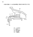
図1は本発明の樹脂爪による部品締結構造の実施例を示す図で、(a)は他方の部品(ヒーターコントロール)に設けられた受け部を示す平面図、(b)は(a)図のZ矢示図、(c)は一方の部品(センタークラスター)に設けられた係合爪を示す平面図、(d)は(c)図のY方向より見た図を一方の部品(センタークラスター)と共に示す図である。 1A and 1B are diagrams showing an embodiment of a component fastening structure using a resin nail according to the present invention. FIG. 1A is a plan view showing a receiving portion provided on the other component (heater control), and FIG. (C) is a plan view showing an engaging claw provided on one part (center cluster), (d) is a part viewed from the Y direction of (c) figure. It is a figure shown with a cluster.
本実施例は図1に示すように、一方の部品20(センタークラスター)に他方の部品30(ヒーターコントロール)とを締結するための締結構造であり、一方の部品20には、所定幅を有する板状の係合爪21が延設され、他方の部品30には前記係合爪21を係合保持する受け部31が設けられている。そして(c)(d)図に示すように、前記係合爪21の先端の左右は後述するゲート部33を通過し易いように斜めに切り落されて斜面21aが形成されている。
As shown in FIG. 1, the present embodiment is a fastening structure for fastening one part 20 (center cluster) to the other part 30 (heater control), and one
また該係合爪21の先端近傍には後述する他方の部品の係合突起34に係合するための係合孔22が穿設されている。更に、該係合爪21の左右の上面及び下面にはその長手方向に沿って補強用のリブ23が形成されている。また、前記係合孔22の係合突起34に係合する面22aには、係合を解除するとき円滑に解除できるように僅かな傾斜がつけられている。
Further, an
また、受け部31は図1(a)(b)に示すように、他方の部品30に取り付けられたブラケット32に前記係合爪21を案内するためのゲート部33と、前記係合爪21の係合孔22に係合して係止する係合突起34とが設けられている。
As shown in FIGS. 1A and 1B, the
そして、前記ゲート部33は図1(a)(b)に示すように、八の字状に開いた入り口部33aと前記係合爪21を案内する案内部33bとよりなり、該案内部33bは前記係合爪21をガタなく案内できる大きさとなっている。また、係合突起34は前記係合爪21の先端を案内する斜面34bと前記係合孔22の係合面22aに対応した斜面34aを有する変形山形状をなしている。また、該突起34の斜面34aの下方には突起34と係合爪21との係合を解除する際に、係合爪21の下方にドライバーを案内するための小斜面部35が3個設けられている。
As shown in FIGS. 1 (a) and 1 (b), the
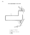
このように構成された本実例の作用を図1及び図2により説明する。先ず、図1(b)(d)の状態から他方の部品30を一方の部品20に向かって矢印A方向に移動させ、そのゲート部33に一方の部品20の係合爪21を挿入させれば、該係合爪21はその左右及び補強リブ23により上下左右を入り口部33a及び案内部33bに案内されて進行し、さらに係合爪21の先端が係合突起34の斜面34bを乗り越えて係合孔22が係合突起34の斜面34aに係合する。このようにして両部品20,30は図2の如く締結状態となる。
The operation of this example configured as described above will be described with reference to FIGS. First, the
なお、締結を解除するには、図2において、係合爪21の先端と小斜面部35との間に矢印B方向から図示なきマイナスドライバーを差込み、捩じることにより係合突起34と係合孔22の係合を容易に解除することができる。
In order to release the fastening, in FIG. 2, a minus driver (not shown) is inserted between the tip of the
以上、本発明を特にその最良の形態について説明した。最後のまとめとして、本発明の構成及びそのバリエーションを以下に付記として列挙する。
前記実施例は自動車のセンタークラスターとヒーターコントロールとの結合を対象に説明したが、その他の、2つの部品を結合する場合にも応用可能である。
The present invention has been particularly described with respect to its best mode. As a final summary, the configurations of the present invention and variations thereof are listed below as supplementary notes.
Although the above embodiment has been described with respect to the combination of the vehicle center cluster and the heater control, the present invention can also be applied to the combination of two other components.
20、30…部品
21…係合爪
21a…斜面
22…係合孔
22a…係合面
23…補強リブ
23a,34a,34b…斜面
31…受け部
32…ブラケット
33…ゲート部
33a…入り口部
33b…案内部
34…係合突起
35…小斜面部
20, 30 ...
Claims (4)
前記係合爪(21)は、一方の部品(20)より延設され、且つ先端近傍に係合孔(22)が穿設された板状片であり、
前記受け部(31)は、前記係合爪(21)を案内するゲート部(33)と、前記係合爪(21)の係合孔(22)に係合して係止する係合突起(34)とを有することを特徴とする樹脂爪による部品締結構造。 In order to connect the other part (30) to one part (20), the one part (20) is provided with a resin engaging claw (21), and the other part (30) is provided with the engaging claw (21). ) Is a component fastening structure with a resin nail provided with a receiving portion (31) for locking,
The engaging claw (21) is a plate-like piece extending from one component (20) and having an engaging hole (22) formed near the tip.
The receiving portion (31) includes a gate portion (33) for guiding the engagement claw (21) and an engagement protrusion that engages and engages with the engagement hole (22) of the engagement claw (21). (34) A component fastening structure using a resin nail.
Priority Applications (1)
| Application Number | Priority Date | Filing Date | Title |
|---|---|---|---|
| JP2004104072A JP2005291265A (en) | 2004-03-31 | 2004-03-31 | Part tightening structure by resin-made claw |
Applications Claiming Priority (1)
| Application Number | Priority Date | Filing Date | Title |
|---|---|---|---|
| JP2004104072A JP2005291265A (en) | 2004-03-31 | 2004-03-31 | Part tightening structure by resin-made claw |
Publications (1)
| Publication Number | Publication Date |
|---|---|
| JP2005291265A true JP2005291265A (en) | 2005-10-20 |
Family
ID=35324438
Family Applications (1)
| Application Number | Title | Priority Date | Filing Date |
|---|---|---|---|
| JP2004104072A Pending JP2005291265A (en) | 2004-03-31 | 2004-03-31 | Part tightening structure by resin-made claw |
Country Status (1)
| Country | Link |
|---|---|
| JP (1) | JP2005291265A (en) |
Cited By (2)
| Publication number | Priority date | Publication date | Assignee | Title |
|---|---|---|---|---|
| JP2009127732A (en) * | 2007-11-22 | 2009-06-11 | Oki Joho Systems:Kk | Securing structure |
| JP2014151678A (en) * | 2013-02-05 | 2014-08-25 | Toyota Motor Corp | Coupling structure and bumper cover structure of resin component |
-
2004
- 2004-03-31 JP JP2004104072A patent/JP2005291265A/en active Pending
Cited By (3)
| Publication number | Priority date | Publication date | Assignee | Title |
|---|---|---|---|---|
| JP2009127732A (en) * | 2007-11-22 | 2009-06-11 | Oki Joho Systems:Kk | Securing structure |
| JP2014151678A (en) * | 2013-02-05 | 2014-08-25 | Toyota Motor Corp | Coupling structure and bumper cover structure of resin component |
| US9598034B2 (en) | 2013-02-05 | 2017-03-21 | Toyota Jidosha Kabushiki Kaisha | Structure for joining resin parts and bumper cover structure |
Similar Documents
| Publication | Publication Date | Title |
|---|---|---|
| US8046880B2 (en) | Clip | |
| CN101688549B (en) | Latching device | |
| CN101421524B (en) | Article fixture | |
| JP2009047305A (en) | Fixation device, structure for fixing member, method of fixing fixed member, and method of releasing fixation effected by fixation device | |
| US20040105720A1 (en) | One-touch cap for fixing a control cable | |
| WO2007126201A1 (en) | Automotive fastener | |
| JP2006046537A (en) | Fastener | |
| JP6000068B2 (en) | Cover attachment / detachment structure for vehicle bumper | |
| JP4283136B2 (en) | Fixed structure, protector and electrical junction box | |
| JP2005291265A (en) | Part tightening structure by resin-made claw | |
| JP2010144830A (en) | Fastener | |
| JP6115945B2 (en) | Clamp structure for battery fixed holding | |
| JP5138019B2 (en) | Equalizer for parking brake | |
| JP3459769B2 (en) | Footrest device | |
| JP2007510576A (en) | Unit carrier with integral locking device for vehicle doors | |
| JP4950674B2 (en) | clip | |
| JP2006066155A (en) | Lever switch mounting structure | |
| KR101476857B1 (en) | Band Cable | |
| JP2007143274A (en) | Clamp | |
| JP2001173614A (en) | Clip | |
| JP3828752B2 (en) | Wiring clip | |
| JP2007320373A (en) | Vehicular lamp, mounting method for vehicle lamp, mounting structure for vehicle lamp, and vehicle | |
| JP2008123899A (en) | Connector having cover | |
| JP2009142128A (en) | Electrical connection box | |
| JP2002120662A (en) | Mounting structure of vehicular exterior part |
Legal Events
| Date | Code | Title | Description |
|---|---|---|---|
| A621 | Written request for application examination |
Free format text: JAPANESE INTERMEDIATE CODE: A621 Effective date: 20061016 |
|
| A131 | Notification of reasons for refusal |
Free format text: JAPANESE INTERMEDIATE CODE: A131 Effective date: 20090210 |
|
| A977 | Report on retrieval |
Free format text: JAPANESE INTERMEDIATE CODE: A971007 Effective date: 20090212 |
|
| A02 | Decision of refusal |
Free format text: JAPANESE INTERMEDIATE CODE: A02 Effective date: 20090630 |