JP2005291242A - Joint member - Google Patents
Joint member Download PDFInfo
- Publication number
- JP2005291242A JP2005291242A JP2004103515A JP2004103515A JP2005291242A JP 2005291242 A JP2005291242 A JP 2005291242A JP 2004103515 A JP2004103515 A JP 2004103515A JP 2004103515 A JP2004103515 A JP 2004103515A JP 2005291242 A JP2005291242 A JP 2005291242A
- Authority
- JP
- Japan
- Prior art keywords
- housing
- pipe
- joint member
- joint
- pin
- Prior art date
- Legal status (The legal status is an assumption and is not a legal conclusion. Google has not performed a legal analysis and makes no representation as to the accuracy of the status listed.)
- Pending
Links
Images


Landscapes
- Joining Of Building Structures In Genera (AREA)
- Mutual Connection Of Rods And Tubes (AREA)
Abstract
Description
本発明は、パイプ部材を接合するためのジョイント部材に関する。 The present invention relates to a joint member for joining pipe members.
例えばクリーンルーム等の構造体を組み立てる際の骨格材料として、ステンレス等の金属を材質とする中空角パイプが一般的に用いられている。中空角パイプは、板状の金属部材が折り曲げられると共に折り曲げの隙間部分が溶接にて接合されている。このような中空角パイプは、広く市販されている。かかる中空角パイプを用いて上述の構造体を組み立てる場合、現状では中空角パイプ同士を溶接により接合している。 For example, a hollow square pipe made of a metal such as stainless steel is generally used as a skeleton material for assembling a structure such as a clean room. In the hollow square pipe, the plate-like metal member is bent and the bent gap portion is joined by welding. Such hollow square pipes are widely commercially available. When assembling the above-described structure using such a hollow square pipe, at present, the hollow square pipes are joined together by welding.
また、中空角パイプ同士を接合するための手法が、種々考案されている。このうち、特許文献1には、中空角パイプの切り欠き角度を左右で異なる状態で裁断して切欠部を形成し、その後屈曲接合部が形成される状態に屈曲部を折り曲げた後に、レーザ光線を介して該屈曲接合部を接合する手法が開示されている。また、特許文献2には、中空角パイプに切欠部を形成し、2本の中空角パイプの切欠部同士が嵌合する状態で溶接すると共に、上述の特許文献1記載のような屈曲/溶接による中空角パイプの接合方法が開示されている。 Various methods for joining hollow square pipes have been devised. Among them, Patent Document 1 discloses a laser beam after cutting a hollow angle pipe with a notch angle different between right and left to form a notch, and then bending the bent part into a state where a bent joint is formed. A technique for joining the bent joints via a wire is disclosed. Further, in Patent Document 2, a notch is formed in a hollow square pipe and welding is performed in a state where the notches of the two hollow square pipes are fitted with each other, and bending / welding as described in Patent Document 1 described above is performed. Discloses a method for joining hollow square pipes.
ところで、溶接を行う場合、溶接箇所の全周に亘って均等に溶接する必要がある。また、溶接を行うと、温度変化(冷却)に伴なって、溶接箇所に変形が生じることが多く、そのような変形が生じると、2つのパイプ部材の間で曲がりが生じたり、ねじれが生じて、接合精度が悪化する等の問題がある。かかる問題を少なくするためには、熟練した作業者が溶接作業を行う必要がある。しかしながら、溶接作業に熟練した作業者は、年々減少しており、確保し難くなっているという問題がある。 By the way, when performing welding, it is necessary to weld uniformly over the perimeter of a welding location. In addition, when welding is performed, the welded portion is often deformed with a change in temperature (cooling). When such a deformation occurs, the two pipe members are bent or twisted. As a result, there is a problem that the joining accuracy deteriorates. In order to reduce such a problem, it is necessary for a skilled worker to perform welding work. However, there is a problem that the number of workers skilled in welding work is decreasing year by year, and it is difficult to secure.
また、上述の溶接を行う場合、接合精度を出すために専用冶具が必要となる。しかしながら、かかる専用冶具は、組み立てられる構造体の形状等に合わせて製作する必要があり、1つのタイプの構造体が組み立てられた後には、他のタイプの構造体に対して該専用冶具を再利用することが難しい。すなわち、一つの構造体を組み立てた後に、専用冶具を破棄する等の無駄が生じている。また、上述のように、溶接により中空角パイプを精度良く接合する場合、作業時間が掛かるという問題がある。そのため、構造体の製作コストがかさむ、という問題も生じている。 Moreover, when performing the above-mentioned welding, in order to take out joining precision, an exclusive jig is needed. However, such a dedicated jig needs to be manufactured in accordance with the shape of the structure to be assembled. After one type of structure is assembled, the dedicated jig is re-mounted with respect to another type of structure. It is difficult to use. That is, there is a waste such as discarding the dedicated jig after assembling one structure. In addition, as described above, there is a problem that it takes work time to join the hollow square pipes with high accuracy by welding. Therefore, the problem that the manufacturing cost of a structure increases is also produced.
また、溶接により2つの中空角パイプを接合した場合、その表面には溶加材等が盛り上がり隆起部分が形成されるのが通常である。そのため、該隆起部分を除去すべく、作業者が仕上げ加工を行う場合が多い。それにより、溶接により接合する場合には一層工数がかさむ、という問題がある。さらに、仕上げ加工に伴なう隆起部分の除去、および溶接ムラ等によって、溶接箇所の肉厚にバラツキが生じることが多い。すなわち、仕上げ加工および溶接ムラ等によって、溶接箇所の肉厚寸法が小さい(薄い)箇所が形成される場合もあり、その場合には、外部衝撃の負荷によって、溶接箇所に割れが生じる、という問題もある。 Moreover, when two hollow square pipes are joined by welding, it is normal that a filler material or the like rises on the surface and a raised portion is formed. Therefore, an operator often performs a finishing process in order to remove the raised portion. As a result, there is a problem that man-hours are further increased when joining by welding. Further, the thickness of the welded portion often varies due to the removal of the raised portion accompanying the finishing process and welding unevenness. That is, there may be a case where the thickness of the welded portion is small (thin) due to finishing and welding unevenness, and in that case, a crack occurs in the welded portion due to an external impact load. There is also.
また、構造体を設置する場所(環境)の中には、溶接を行うことができない場所も多く、現状では構造体を組み立てた後に、搬送するケースも多い。しかしながら、構造体は、大きなサイズを有しているのが通常であり、該構造体の搬送にコストがかかる、という問題も生じている。さらに、溶接に先立って中空角パイプを切断する場合、例えば垂直等に中空角パイプを精度良く切断する必要がある。この場合、精度の良い切断のために、時間やコストが掛かる等の問題も生じる。 In addition, there are many places where the structure is installed (environment) where welding cannot be performed, and there are many cases where the structure is assembled and then transported. However, the structure usually has a large size, and there is a problem that it is expensive to transport the structure. Furthermore, when a hollow square pipe is cut prior to welding, it is necessary to cut the hollow square pipe with high accuracy, for example, vertically. In this case, there is a problem that time and cost are required for accurate cutting.
以上、まとめると、現状の溶接による接合では、(1)職人技術が必要である、(2)専用冶具が必要であるが、使用後廃棄する必要がある、(3)仕上げ工程が必要である、(4)組み立てが難しい、(5)精度を出すのが難しい、(6)搬送コストがかかる、(7)強度面でバラツキがある、という問題点がある。 In summary, the current welding joints (1) require craftsmanship, (2) special tools are required, but must be discarded after use, (3) a finishing step is required. (4) Difficult to assemble, (5) Difficult to obtain accuracy, (6) High transportation cost, (7) Variation in strength.
なお、上述の特許文献1および2では、中空角パイプを所定の長さに切断し、または切欠部を形成し、その後に溶接により中空角パイプ同士を接合している。そのため、上述した各課題は、解決されていない。 In Patent Documents 1 and 2 described above, the hollow rectangular pipes are cut into a predetermined length or a notch is formed, and then the hollow rectangular pipes are joined together by welding. Therefore, each subject mentioned above is not solved.
本発明は上記の事情にもとづきなされたもので、その目的とするところは、容易に組み立てられると共に、強度面および精度面で優れ、かつコストを低減できるパイプ部材のジョイント部材を提供しよう、とするものである。 The present invention has been made on the basis of the above circumstances, and its object is to provide a joint member for a pipe member that can be easily assembled, is excellent in strength and accuracy, and can reduce costs. Is.
上記課題を解決するために、本発明は、複数の金属製のパイプ部材を接合するジョイント部材であって、金属製のパイプ部材のうち隣り合う2つのパイプ部材の中空部に差し掛かる状態で充填される躯体を有すると共に、パイプ部材と躯体とを接合する接合部が設けられているものである。 In order to solve the above-described problems, the present invention is a joint member for joining a plurality of metal pipe members, and is filled in a state where the metal pipe members reach the hollow portions of two adjacent pipe members. In addition to having a housing to be provided, a joint portion for joining the pipe member and the housing is provided.
このように構成した場合、2つのパイプ部材の中空部に差し掛かる状態で、躯体が配置される。また、接合部の存在により、2つのパイプ部材のそれぞれと躯体とが接合される。このため、2つのパイプ部材は、ジョイント部材を介して接合される状態となる。このようにすれば、溶接を行わずに、2つのパイプ部材を接合することができる。 When comprised in this way, a housing is arrange | positioned in the state which approaches the hollow part of two pipe members. Moreover, each of two pipe members and a housing are joined by presence of a junction part. For this reason, two pipe members will be in the state joined via a joint member. If it does in this way, two pipe members can be joined, without performing welding.
そのため、職人技術が不要となり、しかも職人技術によらずとも接合精度を出すことができる。また専用冶具も必要とせず、該専用冶具を使用後に廃棄する必要もない。また、仕上げ工程も不要であり、しかも中空部への躯体を挿入するだけのため、組み立ても簡単である。さらに、構造体を現地で組み立てることができるため、搬送コストも安価となる。また、強度面でのバラツキが生じるのを抑えることができる。 This eliminates the need for craftsmanship and can achieve joining accuracy without relying on craftsmanship. Moreover, no special jig is required, and it is not necessary to discard the special jig after use. In addition, a finishing process is unnecessary, and the assembly is easy because only the casing is inserted into the hollow portion. Furthermore, since the structure can be assembled locally, the transportation cost is also low. Moreover, it is possible to suppress the occurrence of variations in strength.
また、他の発明は、上述の発明に加えて更に、躯体は、樹脂を材質とし、該躯体の外周面は中空部の内壁面と接触すると共に、接合部は、躯体から延伸しかつ該躯体と一体的なフック部から構成されると共に、このフック部は、パイプ部材に形成されている係止孔に係止される、こととしたものである。 Further, in addition to the above-described invention, in another invention, the casing is made of resin, the outer peripheral surface of the casing is in contact with the inner wall surface of the hollow portion, and the joint extends from the casing and the casing And the hook portion is locked in a locking hole formed in the pipe member.
このように構成した場合には、フック部が係止孔に係止されることにより、パイプ部材と躯体とが接合される。このため、フック部と係止孔との係止により、2つのパイプ部材は、ジョイント部材を介して接合される状態となる。このようにすれば、溶接を行わずに、2つのパイプ部材を接合することができる。また、フック部と係止孔との間の係止を解くことにより、ジョイント部材を中空部から抜くことができ、他のパイプ部材の接合のために、該ジョイント部材を再度利用することが可能となる。 When comprised in this way, a pipe member and a housing are joined because a hook part is latched by a latching hole. For this reason, two pipe members will be in the state joined via a joint member by latching with a hook part and a latching hole. If it does in this way, two pipe members can be joined, without performing welding. Also, by releasing the locking between the hook part and the locking hole, the joint member can be removed from the hollow part, and the joint member can be reused for joining other pipe members. It becomes.
かかる構成の場合も、職人技術が不要となり、しかも職人技術によらずとも接合精度を出すことができる。また専用冶具も必要とせず、該専用冶具を使用後に廃棄する必要もない。また、仕上げ工程も不要であり、しかも中空部への躯体を挿入するだけのため、組み立ても簡単である。さらに、構造体を現地で組み立てることができるため、搬送コストも安価となる。また、強度面でのバラツキが生じるのを抑えることができる。 Even in such a configuration, the craftsman technique is not required, and the joining accuracy can be achieved without using the craftsman technique. Moreover, no special jig is required, and it is not necessary to discard the special jig after use. In addition, a finishing process is unnecessary, and the assembly is easy because only the casing is inserted into the hollow portion. Furthermore, since the structure can be assembled locally, the transportation cost is also low. Moreover, it is possible to suppress the occurrence of variations in strength.
さらに、他の発明は、上述の発明に加えて更に、躯体の外周面は中空部の内壁面と接触し、かつ躯体はパイプ部材に設けられているピン孔と位置合わせが為される挿通孔を備えると共に、接合部は、挿通孔と、この挿通孔に挿通されるピン部材により構成され、該ピン部材が挿通状態においてピン孔に差し掛かった状態となることにより、パイプ部材と躯体とが接合される、こととしたものである。 Furthermore, in addition to the above-mentioned invention, the invention further includes an insertion hole in which the outer peripheral surface of the housing is in contact with the inner wall surface of the hollow portion, and the housing is aligned with a pin hole provided in the pipe member. And the joint portion is configured by an insertion hole and a pin member inserted into the insertion hole, and the pipe member and the housing are joined by the pin member entering the pin hole in the insertion state. It is supposed to be.
このように構成した場合には、ピン孔と挿通孔とを位置合わせした状態で、ピン部材を両者に差し掛かる状態で挿通させる。すると、ピン部材がピン孔に差し掛かることによって抜け止めとなり、躯体はパイプ部材から抜けずにピン部材により接合された状態となる。すなわち、2つのパイプ部材はジョイント部材を介して接合された状態となる。このようにすれば、溶接を行わずに、2つのパイプ部材を接合することができる。また、ピン部材をピン孔および挿通孔から抜くことにより、ジョイント部材を中空部から抜くことができ、他のパイプ部材の接合のために、該ジョイント部材を再度利用することが可能となる。 When comprised in this way, in the state which aligned the pin hole and the penetration hole, the pin member is inserted in the state which approaches both. Then, when the pin member reaches the pin hole, the pin member is prevented from coming off, and the housing is joined by the pin member without coming off the pipe member. That is, the two pipe members are joined via the joint member. If it does in this way, two pipe members can be joined, without performing welding. Further, by removing the pin member from the pin hole and the insertion hole, the joint member can be extracted from the hollow portion, and the joint member can be reused for joining other pipe members.
かかる構成の場合も、職人技術が不要となり、しかも職人技術によらずとも接合精度を出すことができる。また専用冶具も必要とせず、該専用冶具を使用後に廃棄する必要もない。また、仕上げ工程も不要であり、しかも中空部への躯体を挿入するだけのため、組み立ても簡単である。さらに、構造体を現地で組み立てることができるため、搬送コストも安価となる。また、強度面でのバラツキが生じるのを抑えることができる。 Even in such a configuration, the craftsman technique is not required, and the joining accuracy can be achieved without using the craftsman technique. Moreover, no special jig is required, and it is not necessary to discard the special jig after use. In addition, a finishing process is unnecessary, and the assembly is easy because only the casing is inserted into the hollow portion. Furthermore, since the structure can be assembled locally, the transportation cost is also low. Moreover, it is possible to suppress the occurrence of variations in strength.
また、他の発明は、上述の発明に加えて更に、躯体は、中空部の内壁面と接触すると共に、該内壁面との接触部分に凹部を有していて、接合部は、凹部と、この凹部に貯留される接着剤とによって構成され、該接着剤が硬化することにより、躯体と中空部の内壁面との間で接着力を及ぼす、こととしたものである。 Further, in addition to the above-mentioned invention, the other invention further has a recess in contact with the inner wall surface of the hollow portion and a contact portion with the inner wall surface. The adhesive is stored in the recess, and when the adhesive is cured, an adhesive force is exerted between the housing and the inner wall surface of the hollow portion.
このように構成した場合には、凹部に接着剤が貯留された状態で、中空部に躯体を差し込む。すると、接着剤が硬化すれば、接合部が形成され、この接合部が躯体と中空部の内壁面との間で接着力を及ぼす状態となる。すなわち、2つのパイプ部材はジョイント部材を介して接合された状態となる。このようにすれば、溶接を行わずに、2つのパイプ部材を接合することができる。 When comprised in this way, a housing is inserted in a hollow part in the state by which the adhesive agent was stored by the recessed part. Then, if an adhesive agent hardens | cures, a junction part will be formed and this junction part will be in the state which exerts adhesive force between a housing and the inner wall face of a hollow part. That is, the two pipe members are joined via the joint member. If it does in this way, two pipe members can be joined, without performing welding.
かかる構成の場合も、職人技術が不要となり、しかも職人技術によらずとも接合精度を出すことができる。また専用冶具も必要とせず、該専用冶具を使用後に廃棄する必要もない。また、仕上げ工程も不要であり、しかも中空部への躯体を挿入するだけのため、組み立ても簡単である。さらに、構造体を現地で組み立てることができるため、搬送コストも安価となる。また、強度面でのバラツキが生じるのを抑えることができる。 Even in such a configuration, the craftsman technique is not required, and the joining accuracy can be achieved without using the craftsman technique. Moreover, no special jig is required, and it is not necessary to discard the special jig after use. In addition, a finishing process is unnecessary, and the assembly is easy because only the casing is inserted into the hollow portion. Furthermore, since the structure can be assembled locally, the transportation cost is also low. Moreover, it is possible to suppress the occurrence of variations in strength.
さらに、他の発明は、上述の発明に加えて更に、躯体は、ポリウレタンフォームが硬化した発泡生成物から構成されると共に、躯体の外周面が中空部の内壁面と接合する接合部となっている、こととしたものである。 Furthermore, in addition to the above-described invention, in another invention, the casing is composed of a foamed product obtained by curing polyurethane foam, and the outer peripheral surface of the casing serves as a joint portion that joins the inner wall surface of the hollow portion. It is what it is.
このように構成した場合には、硬化した発泡生成物が中空部の内部で形成されることにより、該発泡生成物の外周面が接合部となって、中空部の内壁面と接合する。それにより、2つのパイプ部材は、この発泡生成物を介して接合された状態となる。このようにすれば、溶接を行わずに、2つのパイプ部材を接合することができる。 When comprised in this way, when the hardened foamed product is formed inside a hollow part, the outer peripheral surface of this foamed product becomes a junction part, and it joins with the inner wall surface of a hollow part. Thereby, two pipe members will be in the state joined via this foaming product. If it does in this way, two pipe members can be joined, without performing welding.
かかる構成の場合も、職人技術が不要となり、しかも職人技術によらずとも接合精度を出すことができる。また専用冶具も必要とせず、該専用冶具を使用後に廃棄する必要もない。また、仕上げ工程も不要であり、しかも中空部への躯体を挿入するだけのため、組み立ても簡単である。さらに、構造体を現地で組み立てることができるため、搬送コストも安価となる。また、発泡生成物の充填により、パイプ部材の強度も向上すると共に、接合部位における強度面でのバラツキが生じるのを抑えることができる。 Even in such a configuration, the craftsman technique is not required, and the joining accuracy can be achieved without using the craftsman technique. Moreover, no special jig is required, and it is not necessary to discard the special jig after use. In addition, a finishing process is unnecessary, and the assembly is easy because only the casing is inserted into the hollow portion. Furthermore, since the structure can be assembled locally, the transportation cost is also low. Moreover, the filling of the foamed product can improve the strength of the pipe member, and can suppress the occurrence of variations in strength at the joint site.
本発明によると、ジョイント部材を用いることで、パイプ部材を容易に接合することができる。また、強度面および精度面で優れた接合を実現でき、かつコストを低減することができる。 According to the present invention, the pipe member can be easily joined by using the joint member. Further, it is possible to realize excellent bonding in terms of strength and accuracy, and to reduce costs.
(第1の実施の形態)
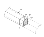
以下、本発明の第1の実施の形態に係るジョイント部材について、図1および図2に基づいて説明する。図1は、ジョイント部材10の構成を示す斜視図である。また、図2は、ジョイント部材10を用いてパイプ部材50を接合するイメージを示す分解斜視図である。
(First embodiment)
Hereinafter, a joint member according to a first embodiment of the present invention will be described with reference to FIGS. 1 and 2. FIG. 1 is a perspective view showing the configuration of the
図1に示すジョイント部材10は、躯体20と、フック部30と、フランジ部40と、を有している。ジョイント部材10は、例えばABS樹脂(アクリロニトリル、ブタジエン、スチレンからなる熱可塑性樹脂)を材質として形成されている。しかしながら、強度に優れる樹脂であれば、かかるABS樹脂には限定されない。他の材質の樹脂の例としては、RENY(ガラス繊維50%強化ポリアミドMXD6)、PEEK(ポリエーテルエーテルケトン)、PPS(ポリフェニレンサルファイド)、PC(ポリカーボネード)等がある。
The
躯体20は、その外観が略直方体形状を為している。また、躯体20の平面形状は、略正方形となっている。この躯体20の側面21a〜21dのうち、平行を為す2つの側面21a,21cには、溝部22が設けられている。溝部22は、躯体20の長手に沿うように設けられていると共に、側面21a,21cを突っ切って、開放した状態となっている。
The
溝部22は、本実施の形態では、それぞれの側面21a,21cに2つずつ、合計4つ設けられている。溝部22は、中空角パイプ(以下、パイプ部材50とする。)の中空部51に存在する、溶接による肉盛り部分を逃がすための部分である。すなわち、パイプ部材50は、金属の板状部材の折り曲げ、溶接等により形成されるが、通常、中空部51には隆起している肉盛り部分が残存した状態となっている。そのため、溝部22の存在により、躯体20は肉盛り部分を逃がすことが可能となっている。
In the present embodiment, a total of four
また、躯体20の上端面23aおよび下端面23bには、それぞれフック部30が設けられている。フック部30は、接合部に対応するものであり、ロッド部31と、鍵部32とを有している。このうちロッド部31は、断面が矩形状となっている長尺部材である。ロッド部31のうち一側面31aは、躯体20の側面21b,21dと面一となるように設けられている。
Moreover, the
また、鍵部32は、ロッド部31の先端側に設けられている。鍵部32は、ロッド部31の一側面31aから隆起する突出部33を有している。突出部33のうち躯体20側の部位には、上述の一側面31aに対して略垂直となる係止面33aが設けられている。この係止面33aは、後述するパイプ部材50の係止孔52の側縁52aに係止される。また、突出部33のうち突出の頂部33bよりも躯体20から離間する側には、ガイド面33cが設けられている。ガイド面33cは、躯体20から離間するにつれて、突出高さが低くなるテーパ形状を為している。このガイド面33cは、後述するパイプ部材50の中空部51に対するロッド部31の挿入を、ガイドする部分である。
The
本実施の形態では、このようなフック部30が、溝部22が設けられていない、互いに平行を為す側面21b,21dに沿うように設けられている。また、フック部30は、上端面23aおよび下端面23bのそれぞれから、2つずつ突出している。それにより、ジョイント部材10は、パイプ部材50に対して略均等な状態で係止される。
In the present embodiment, such a
また、躯体20のうち、上端面23aと下端面23bの中間に位置する部位には、該上端面23aおよび下端面23bに対して略平行となる状態で、フランジ部40が設けられている。フランジ部40は、4つの側面21a〜21dから突出して設けられている。それにより、フランジ部40の平面形状は、躯体20よりも縦横の寸法の大きな矩形状に設けられている。また、フランジ部40の突出の程度は、パイプ部材50の表面と同程度か、僅かに凹む程度に設けられている。しかしながら、外観上および機能上問題とならない場合には、フランジ部40がパイプ部材50の表面より突出する状態であっても良い。なお、フランジ部40を省略する構成を採用しても良い。なお、同一面に形成されている溝部22は、フランジ部40によって長さ方向で2つに区切られている。
Moreover, the
また、フランジ部40を設ける代わりに、例えばピン形状の突起を設けることも可能である。この場合、後述するパイプ部材50には、ピン形状の突起に対応した、図5の挿通孔24aと同様の挿通孔を形成する必要がある。この場合、ピン形状の突起は、フランジ部40よりも、外観上、ユーザ等の目に触れる機会を少なくする(目立たなくする)ことができる。なお、挿通孔にピン形状の突起が位置する場合、該突起を挿通孔から外方に突出させないようにするのが好ましい。
Further, instead of providing the
次に、パイプ部材50の構造について説明する。図2に示すパイプ部材50は、中空角パイプであり、冷間圧延ステンレス鋼帯を素材とし、該鋼帯を折り曲げると共に、例えばTIG(イナートガスタングステンアーク)溶接または高周波誘導溶接により、断面が中空角形状となるように造管した管部材である。
Next, the structure of the
このパイプ部材50には、その長手方向に沿って内部を貫く空間部分である、中空部51が設けられている。また、パイプ部材50には、係止孔52が設けられている。係止孔52は、上述した鍵部32を位置させる(嵌め込む)ための部分である。そのため、係止孔52は、上述の鍵部32の寸法に対応した寸法を有している。それによって、鍵部32をこの係止孔52に嵌め込んだ場合、当該鍵部32がガタ付かない状態で嵌合状態を維持可能となっている。
The
なお、係止孔52は、上述の鍵部32を該鍵部32の上方から見た形状(略矩形状)に対応して、矩形状の孔となっている。この係止孔52は、例えば3次元レーザ加工装置を用いた孔開け加工により形成されている。また、係止孔52の個数は、上述の鍵部32の個数に対応して、パイプ部材50のうち平行を為す2つの側面50a,50cのそれぞれに1つずつ、合計2つ設けられている。
The locking
また、係止孔52は、パイプ部材50の一端部の側縁53から、所定の寸法だけ離間した部位に設けられている。ここで、パイプ部材50の側縁53には、上述のフランジ部40が当接する。このため、フランジ部40が側縁53に当接した状態で、係止面33aが一端部寄りに位置する係止孔52の側縁52aに当接する位置となるように、係止孔52が位置決めされている。
Further, the locking
なお、パイプ部材50の一端側および他端側に存在する側縁53は、例えばデフォルトで、長手方向に垂直に切断された状態となっている。
In addition, the
以上のような構成を有するジョイント部材10を用いて、パイプ部材50を接合する方法について、以下に説明する。
A method of joining the
まず、不図示の構造体を組み立てる設置場所において、作業者は、パイプ部材50の中空部51にフック部30を差し込む。この場合、まずガイド面33cが側縁53の内周側角部に衝突し、その状態でさらにジョイント部材10を中空部51に押し込むと、ロッド部31が内壁面によって押圧され、ロッド部31同士が互いに近接する方向に向かって曲がる撓み変形が生じる。ガイド面33cに続いて、頂部33bが中空部51の内壁面に衝突する状態とし、その状態でジョイント部材10を押し込むと、該頂部33bが内壁面を擦り動きつつ、係止孔52に向かって進行する。
First, an operator inserts the
そして、頂部33bが係止孔52に差し掛かり、該頂部33bが係止孔52を通過し終えると、頂部33bと内壁面との押圧状態が解除され、ロッド部31の撓み変形が取り除かれて、ロッド部31は元の状態に戻る。このとき、係止孔52の側縁52aには、係止面33aが係止する状態となる。すなわち、係止孔52には、鍵部32が嵌まり込む状態となる。また、このとき、フランジ部40には、パイプ部材50の側縁53が当接する状態となる。以上のような嵌まり込みが、全ての係止孔52と鍵部32との間で、ほぼ同時に生じる。それにより、パイプ部材50とジョイント部材10とが接合される。
Then, when the
なお、係止面33aは、パイプ部材50の長手方向に対して略垂直な状態で係止孔52の側縁53と係合している。このため、かかる係止面33aによって、ジョイント部材10の抜け防止が図られる。また、フランジ部40から躯体20の一端までの長さをL1とし、躯体20の幅をW1とし、フック部30の長さをL2とした場合、W1/3≦L1≦W1とするのが、取付強度がコスト等の面から好ましく、L1/2≦L2≦L1とするのが、組み立て易さやフック部30の弾性力等の面から好ましい。
The locking
また、フランジ部40を挟んで、パイプ部材50が上述のようにして取り付けられた側と反対側においても、同様の手順で、ジョイント部材10を中空部51に押し込むことにより、パイプ部材50とジョイント部材10とが接合される。なお、パイプ部材50の他端側にも同様のジョイント部材10を差し込むことにより、複数のパイプ部材50を連結することが可能となる。また、ジョイント部材10を中央にして、2つのパイプ部材50,50を両側から押し込んでいく方法を採用することもできる。
Further, the
次に、上述のジョイント部材10の変形例について説明する。なお、かかる変形例においては、上述のジョイント部材10と同様の部分に対しては、同一の符号を用いて説明する。
Next, a modified example of the
図3に示すジョイント部材11は、その全体がL字形状を為す状態に設けられていて、躯体20が一方向(図3におけるX方向)に沿って設けられているのみならず、該一方向と直交する方向(図3におけるY方向)にも沿うように躯体20が設けられている。すなわち、躯体20がL字形状を為している。なお、図3に示す構成では、フランジ部40は設けられていないが、フランジ部40を、躯体20の折れ曲がりの境界部分において、上述のX方向およびY方向に対してそれぞれ略45度を為すように設けても良い。
The joint member 11 shown in FIG. 3 is provided in an L-shaped state as a whole, and the
このような構成のジョイント部材11を用いる場合、パイプ部材50の一端部も、該パイプ部材50の長手方向およびパイプ部材50の幅方向に対して、略45度を為す平面で切断されるようにしても良い(図3は、このような場合を想定)。この場合、2つのパイプ部材50の中空部51にジョイント部材11が挿入され、側縁53が当接する状態となると、パイプ部材50も互いに垂直を為す状態となる。
When the joint member 11 having such a configuration is used, one end of the
また、図4に示すジョイント部材12は、X方向およびY方向に加えて、さらにZ方向に延伸している。すなわち、3方向に延伸している。そのため、ジョイント部材12においては、上述のようにして中空部51にジョイント部材12を挿入すれば、3本のパイプ部材50を接合することが可能となる。なお、この場合も、フランジ部40を設けるようにしても良く、該フランジ部40を省略する構成を採用しても良い。
Further, the
その他、躯体20を適宜の方向に向けて延伸させることにより、4本のパイプ部材50を接合可能なジョイント部材、5本のパイプ部材50を接合可能なジョイント部材、および6本のパイプ部材50を接合可能なジョイント部材を、適宜用いることが可能である。また、躯体20を適宜の傾斜角度に折り曲げることにより、2つのパイプ部材50が傾斜する状態で、接合させることもできる。
In addition, by extending the
このような構成のジョイント部材10およびジョイント部材10を用いた接合方法によれば、ジョイント部材10が中空部51に差し込まれると、2つのパイプ部材50の中空部51に躯体20が差し掛かる状態となる。このとき、係止孔52に鍵部32が嵌め込まれ、係止面33aと側縁53とが係合するため、複数のパイプ部材50を、溶接せずに接合することができる。
According to the
そのため、溶接に際して必要である、精度の良い位置決め状態を維持しながら、溶接箇所に生じる変形を考慮した溶接作業が不要となる。すなわち、職人技術によらずとも、2つのパイプ部材50の間における接合精度を出すことができる。また、溶接の際の精度出しのために、専用冶具も必要としないため、溶接に際して組み立てられる構造体毎に必要となる専用冶具を使用後に廃棄する必要もない。
This eliminates the need for a welding operation that takes into account the deformation that occurs in the welded part while maintaining a highly accurate positioning state that is necessary for welding. That is, the joining accuracy between the two
さらに、溶接を行わずにジョイント部材10を挿入するだけのため、パイプ部材50の接合に必要な時間の短縮を図ることができる。そのため、単位時間当たりに、より多くの接合を実現でき、製作コストを削減することができる。さらに、溶接を行う場合に生じる、溶加材の盛り上がり(肉盛り部分)も生じない。そのため、肉盛り部分を除去する仕上げ加工も不要となり、一層接合のための時間を短縮することができる。また、仕上げ加工および溶接ムラ等により、溶接箇所の肉厚寸法が小さい(薄い)箇所が形成されることもなく、耐衝撃性が接合箇所の周方向において均等となる。
Furthermore, since only the
また、仕上げ加工の際には、通常バフ磨きが行われ、それに伴なってバフ粉が発生する。ここで、バフ粉を除去するのは工数が非常にかかり、その完全な除去は困難であるが、上述のように仕上げ加工が不要となるため、バフ粉を除去作業が不要となり、工数を大幅に削減することができる。また、バフ粉が発生しないため、パイプ部材30により組み立てられる構造体を、例えばクリーンルームに用いても、クリーン度に悪影響を及ぼすことがない。
In finishing processing, buffing is usually performed, and buff powder is generated accordingly. Here, it takes a lot of man-hours to remove the buffing powder, and it is difficult to completely remove the buffing powder. However, as described above, the finishing process is unnecessary, so the buffing powder is not required to be removed and the man-hour is greatly increased. Can be reduced. Moreover, since buff powder does not occur, even if the structure assembled by the
さらに、ジョイント部材10を中空部51に挿入するだけのため、構造体が設置される現地で接合作業を行うことが可能となる。そのため、構造体が組み立てられた状態で搬送する必要がなく、パイプ部材50およびジョイント部材10を搬送するだけで済む。そのため、搬送に要するコストも低減することができる。
Furthermore, since only the
また、3次元レーザ加工装置を用いて、係止孔52を形成(切断)した場合には、その切断により形成される切断面は、垂直度が高い状態となる。この場合、係止面33aが一端部寄りに位置する係止孔52の側縁52aに対して、精度の良い状態で係止される。
In addition, when the locking
また、ジョイント部材10には、フランジ部40が設けられていて、このフランジ部40は躯体20の長手方向における中途部分に位置している。そのため、2つのパイプ部材50がジョイント部材10を介して接合された場合、最も応力が集中する、長手方向の中途部分が、フランジ部40の存在によって強化される。それにより、ジョイント部材10は、一層外部衝撃に対して破損し難い構成となっている。
Further, the
さらに、ジョイント部材10は、フック部30を具備している。そのため、フック部30を中空部51に挿入する場合、このフック部30に撓み変形が生じ、容易に挿入することができる。また、鍵部32が係止孔52に係止している状態においては、該鍵部32と係止孔52との係合状態を外すことにより、中空部51からジョイント部材10を容易に抜くことができる。そのため、抜き取ったジョイント部材10を、他のパイプ部材50との接合において再利用することが可能となる。
Further, the
(第2の実施の形態)
以下、本発明の第2の実施の形態について説明する。図5は、本発明の第2の実施の形態に係るジョイント部材100の構成を示す側面図である。この図5に示すジョイント部材100は、躯体20と、ピン部材110との2部材から構成されている。なお、本実施の形態における躯体20には、上述のフック部30が突出して設けられていない。
(Second Embodiment)
Hereinafter, a second embodiment of the present invention will be described. FIG. 5 is a side view showing the configuration of the
また、躯体20には、その側面21a,21cから接合部の一部となる3つの挿通孔24a〜24cが形成されている。挿通孔24a〜24cは、躯体20を貫通するように形成されている。しかしながら、挿通孔24a〜24cは、躯体20を必ずしも貫通する必要はなく、例えば中途部まで存在する状態であっても良い。なお、挿通孔24が躯体20を貫通しない場合、例えば挿通孔24をネジ孔に形成するようにしても良い。
Further, the
また、挿通孔24a〜24cは、図5においては、躯体20の短手方向のうち略中央部分に設けられていると共に、躯体20の長手方向に沿って3つ設けられている。挿通孔24a〜24cには、後述するピン部材110が挿入される。本実施の形態では、略中央に位置する挿通孔24aから長手方向の一端側に向かい、所定の間隔を経て挿通孔24bが1つ設けられていると共に、略中央に位置する挿通孔24aから長手方向の他端側に向かい、該一端側の挿通孔24とb同じ間隔を経て挿通孔24cが1つ設けられている。
In addition, in FIG. 5, the insertion holes 24 a to 24 c are provided at a substantially central portion in the short direction of the
また、パイプ部材50には、上述した係止孔52が設けられていない。その代わり、パイプ部材50には、上述の挿通孔24a〜24cに対応するピン孔54a,54bが設けられている。ピン孔54a,54bは、上述の挿通孔24a〜24cと同程度の直径を有している。また、ピン孔54a,54bには、後述するピン部材110が挿入される。また、図5に示すように、長手方向の略中央に位置するピン孔54aは、2つのパイプ部材50に跨るように、分割されている。すなわち、長手方向の略中央に位置するピン孔54は、それぞれのパイプ部材50の縁部53を半円状に切り欠いて構成されている(以下、半円状の切り欠きを半円部55とする)。そして、2つの半円部55が合わされることで、円形のピン孔54aが構成される。
Further, the above-described
また、ピン孔54a,54bおよび挿通孔24a〜24cには、接合部の一部となるピン部材110が挿入される。ピン部材110は、パイプ部材50の縦横の寸法と同程度の長さを有しているが、該パイプ部材50の縦横の寸法よりも若干短くても良い。しかしながら、若干短い場合でも、ピン孔54a,54bにパイプ部材50が差し掛かる必要がある。
Moreover, the
なお、挿通孔24aを設けずに、この部分に突出ピンを設けるようにしても良い。この場合、突出ピンに対して半円部55が当接することで、パイプ部材50の挿入の位置決めが為される。また、ピン部材110としては、時計のバンド用バネ棒のように、先端ピン部分が棒状部分に出入可能な部材(以下、バネ棒とする。)を用いても良い。かかるバネ棒を用いる場合、先端ピン部分の直径は、棒状部分よりも小径となる。そのため、ピン孔54a,54bの直径は、挿通孔24a〜24cの直径よりも小径にする必要がある。
In addition, you may make it provide a protrusion pin in this part, without providing the
以上のような構成を有するジョイント部材100を用いて、パイプ部材50を接合する方法について、以下に説明する。
A method of joining the
まず、長手方向の略中央に位置する挿通孔24aに、ピン部材110を挿通させる。この場合、ピン部材110は、挿通孔24aが設けられている躯体20の表面よりも、突出した状態とする。この状態で、パイプ部材50の中空部51に、ジョイント部材100を差し込む。それにより、半円部55に、ピン部材110のうち挿通孔24aから突出している部分が当接し、ジョイント部材100の中空部51の内部へ向かう進行が規制される。
First, the
以上のような差し込みを、ジョイント部材100の一端側および他端側において同時かまたは前後して行う。それにより、半円部55の内周縁には、ピン部材110が当接すると共に、2つのパイプ部材50の縁部53が互いに当接する状態となる。なお、半円部55とピン部材110または2つのパイプ部材50の縁部53は、互いに当接する状態ではなく、僅かな隙間を有して近接する状態としても良い。
The above insertion is performed simultaneously or before and after at one end side and the other end side of the
略中央のピン孔54(以下、ピン孔54aとする)および挿通孔24aにピン部材110が差し込まれている状態では、一端側および他端側に位置するピン孔54(以下、ピン孔54bとする)と挿通孔24b,24cとが位置合わせされる。すなわち、略中央のピン孔54aおよび挿通孔24aに、ピン部材110を差し込むことにより、一端側および他端側に位置するピン孔54bと挿通孔24b,24cとの位置決めが、簡単に為される。かかる位置合わせが為された状態で、パイプ部材50のうち一方の表面に存在するピン孔54b,54bから、ピン部材110,100を差し込む。すると、各ピン部材110は挿通孔24b,24cの内部にも位置すると共に、該挿通孔24b,24cを貫通して、パイプ部材50のうち他方の表面に存在するピン孔54b,54bから突出する。
In a state where the
ここで、この後に、ピン部材110が挿通孔24a〜24cおよびピン孔54a,54bから抜けないように、接着剤等でピン部材110を接着固定するようにしても良い。以上のようにして、ジョイント部材100およびピン部材110を介して、2つのパイプ部材50が接合される。また、例えば、ピン部材110が挿通孔24a〜24cに対して、嵌め合いがきつくなる状態で打ち込むようにしても良い。この場合、ピン部材110の打ち込みのために、専用の冶具を用いるのが好ましい。
Here, after this, the
なお、挿通孔24aの代わりに、突出ピンを設ける場合、該突出ピンに半円部55が当接するまで、パイプ部材50の中空部51に、ジョイント部材100を差し込むようにする。それ以外のピン部材110の差し込み等は、上述したのと同様である。
When providing a protruding pin instead of the
このような構成のジョイント部材100およびジョイント部材100を用いた接合方法によれば、かかるジョイント部材100およびピン部材110を用いた場合でも、上述の第1の実施の形態における場合と同様に、溶接せずにパイプ部材50を接合することができる。そのため、職人技術が不要となり、しかも職人技術によらずとも接合精度を出すことができる。また専用冶具も必要とせず、該専用冶具を使用後に廃棄する必要もない。また、仕上げ工程も不要であり、しかも中空部51への躯体20を挿入するだけのため、組み立ても簡単である。さらに、構造体を現地で組み立てることができるため、搬送コストも安価となる。また、強度面でのバラツキが生じるのを抑えることができる。
According to the
また、本実施の形態では、躯体20の挿通孔24a〜24cに、ピン部材110を差し込むだけで、2つのパイプ部材50を接合することができる。そのため、簡易に接合することができる。また、一度挿入されたピン部材110を挿通孔24a〜24cおよびピン孔54bから抜くことにより、中空部51から躯体20を容易に抜くことができる。そのため、抜き取った躯体20を、他のパイプ部材50との接合において再利用することが可能となる。
Moreover, in this Embodiment, the two
(第3の実施の形態)
以下、本発明の第3の実施の形態について説明する。なお、上述の第1の実施の形態で述べたのと同一の部材については、同一の符号を付して説明する。以下、このジョイント部材について説明する。
(Third embodiment)
Hereinafter, a third embodiment of the present invention will be described. The same members as those described in the first embodiment will be described with the same reference numerals. Hereinafter, the joint member will be described.
本実施の形態では、図6に示すようなジョイント部材200を用いている。ジョイント部材200は、躯体20と、接着剤(不図示)とによって構成されている。このジョイント部材200は、上述の第1の実施の形態のようなジョイント部材10とは異なり、フック部30が設けられていない。しかしながら、このジョイント部材200を構成する躯体20には、複数の凹部25(図6においては、1つの側面に2つ)が設けられている。凹部25は、躯体20の表面から所定深さのだけ窪んだ窪み形状を有していて、躯体20を貫通していない。この凹部25には、硬化することにより接合部を構成する接着剤が貯留される。そのため、躯体20の表面において凹部25が占める面積は、躯体20とパイプ部材50との間の接合に適した面積に設定される。
In the present embodiment, a
なお、かかる凹部25は、パイプ部材50の4つの内壁面と接触する全ての表面に設けられていても良く、互いに平行を為す2つの表面のみに設けるようにしても良い。また、凹部25は、躯体20の表面の1つにつき、1つ設けられていても良く、複数設けられていても良い。また、凹部25の平面形状は、円形状、楕円形状、三角形状等、種々の形状に形成することが可能である。
The
凹部25には、接着剤が貯留される。接着剤として適当なものには、エポキシ系接着剤、ポリウレタン系接着剤、シアノアクリレート系接着剤等があるが、これ以外にも種々の接着剤を用いることが可能である。
An adhesive is stored in the
以上のような構成を有するジョイント部材200を用いて、パイプ部材50を接合する方法について、以下に説明する。
A method of joining the
本実施の形態では、躯体20を中空部51に差し込む場合において、凹部25に予め接着剤を貯留させる。そして、該凹部25に接着剤が貯留されている状態で、この躯体20が2つのパイプ部材50の中空部51の両方に差し掛かる状態とする。すると、凹部25に貯留されている接着剤は、時間の経過と共に硬化を開始し、該硬化が為されると躯体20と中空部51の内壁面とは、接合される。
In the present embodiment, when the
なお、上述の凹部25は、躯体20の長手方向において、少なくとも2つ以上設けられるのが好ましい。すなわち、一方のパイプ部材50の中空部51に、長手方向の一端側の凹部25が位置する状態とすると共に、他方のパイプ部材50の中空部51に、長手方向の他端側の凹部25が位置する状態とする。このようにすれば、最初に長手方向の一端側の凹部25に接着剤が貯留された状態で、一方のパイプ部材50の中空部51に、躯体20の半分を差し込む。次に、他方のパイプ部材50の中空部51に、躯体20の残り半分を差し込み、一方のパイプ部材50の側縁53と、他方のパイプ部材50の側縁53とが当接する状態とする。この状態で、所定時間経過すると、2つのパイプ部材50のそれぞれは、共にジョイント部材200に対して接合された状態となる。
In addition, it is preferable that at least two
なお、パイプ部材50に対する躯体20の位置決めを行うために、躯体20に位置決め孔を形成すると共に、上述のピン部材110と同様なピン部材を、位置決め孔に差し込む構成としても良い。また、躯体20の差し込み深さを規定するために、上述の第1の実施の形態のような、フランジ部40を設けるようにしても良い。
In addition, in order to position the
このような構成のジョイント部材200およびジョイント部材200を用いた接合方法によれば、躯体20および接着剤を用いて接合した場合でも、上述の第1の実施の形態における場合と同様に、溶接せずにパイプ部材50を接合することができる。そのため、職人技術が不要となり、しかも職人技術によらずとも接合精度を出すことができる。また専用冶具も必要とせず、該専用冶具を使用後に廃棄する必要もない。また、仕上げ工程も不要であり、しかも中空部51への躯体20を挿入するだけのため、組み立ても簡単である。さらに、構造体を現地で組み立てることができるため、搬送コストも安価となる。また、強度面でのバラツキが生じるのを抑えることができる。
According to the
さらに、接着剤を用いて接合するため、該接着剤が躯体20との間に存在する隙間に入り込むことにより、強固な接合状態を実現できる。このため、2つのパイプ部材50の間においてガタつきが生じずに、強度の高い構造体を製作することが可能となる。
Furthermore, since it joins using an adhesive agent, when this adhesive agent enters the clearance gap which exists between the
(第4の実施の形態)
以下、本発明の第4の実施の形態について、図7に基づいて説明する。本実施の形態では、中空部51の内部においてウレタン発泡を行うことにより、2つのパイプ部材50を接合している。以下、その詳細について説明する。
(Fourth embodiment)
Hereinafter, a fourth embodiment of the present invention will be described with reference to FIG. In the present embodiment, two
本実施の形態では、2つのパイプ部材50の側縁53が、互いに接合した状態とすると共に、2つのパイプ部材50の内部に、混合溶液を注入する。混合溶液は、ポリオールを主成分とする一方の溶液と、イソシアネートを主成分とする他方の溶液とを混合し、それを混ぜ合わせることにより作成される。かかる混合溶液が発泡し後に硬化すると、発泡生成物300(硬質ポリウレタンフォーム)を構成する。なお、この発泡生成物300が、ジョイント部材および躯体に対応する。
In the present embodiment, the side edges 53 of the two
かかる接合を行う場合、パイプ部材50の側面に形成されている孔部等(不図示)に漏斗等の注入ガイドを差し込み、該注入ガイドから、混合溶液を適量だけ注入する。すると、中空部51において混合溶液が発泡し、発泡生成物300が形成される。発泡生成物300は、時間が経過すると、中空部51の内部において硬化する。以上のようにして、発泡生成物300が硬化すると、該発泡生成物300が2つのパイプ部材50の中空部51に跨る状態で存在すると共に、この発泡生成物300と2つのパイプ部材50の中空部51の内壁面とが接合される。なお、この場合、発泡生成物300の外面が、接合部となる。
When performing such joining, an injection guide such as a funnel is inserted into a hole or the like (not shown) formed on the side surface of the
なお、かかる構成においては、発泡生成物300の中空部51における係止を良好にするために、パイプ部材50に複数の孔部を形成したり、中空部51の内壁面に凹凸を形成するようにしても良い。この場合、孔部や凹凸に入り込む状態で発泡生成物300が硬化することにより、該発泡生成物300が中空部51から抜け難くなる。
In such a configuration, a plurality of holes are formed in the
このような構成のジョイント部材(発泡生成物300)および発泡生成物300を用いた接合方法によれば、かかる発泡生成物300を用いて接合した場合でも、上述の第1の実施の形態における場合と同様に、溶接せずにパイプ部材50を接合することができる。そのため、職人技術が不要となり、しかも職人技術によらずとも接合精度を出すことができる。また専用冶具も必要とせず、該専用冶具を使用後に廃棄する必要もない。また、仕上げ工程も不要であり、しかも中空部51へ混合溶液を注入するだけのため、組み立ても簡単である。さらに、構造体を現地で組み立てることができるため、搬送コストも安価となる。また、強度面でのバラツキが生じるのを抑えることができる。
According to the joining method using the joint member (foamed product 300) and the foamed
さらに、硬質ポリウレタンフォームからなる発泡生成物300は、例えば合成枕木、車の補強材としても使用される等、強度的にも優れるものであるため、2つのパイプ部材50の接合状態が強固なものとなる。また、発泡生成物300が中空部51に充填されることにより、パイプ部材50で構成される構造体の強度も向上する。
Further, the foamed
以上、本発明の一実施の形態について説明したが、本発明はこれ以外にも種々変形可能となっている。以下、それについて述べる。 Although one embodiment of the present invention has been described above, the present invention can be variously modified in addition to this. This will be described below.
上述の第1の実施の形態では、フック部30は躯体20と一体的に設けられている。しかしながら、フック部30は躯体20と一体的とはせずに、別体的に設けるようにしても良い。また、上述の第1〜第3の実施の形態においては、樹脂を材質とするジョイント部材10,100,200について説明している。しかしながら、ジョイント部材10,100,200は、必ずしも樹脂を材質とする構成には限られず、例えば金属を材質とする構成であっても良い。なお、金属材質の一例としては、各種のSUS(ステンレス)がある。
In the above-described first embodiment, the
また、上述の第1の実施の形態においては、フック部30の上端面23aおよび下端面23bにおける付け根部分に、なだらかに幅の広がる補強部を設けるようにしても良い。また、上述の第1の実施の形態では、溝部22を凹状となる形状としていたが、各側面21a〜21dの短手方向の端部を削り取る切削部を設けることにより、溝部22の代わりに溶接による肉盛り部分を逃がすようにしても良い。
Further, in the first embodiment described above, reinforcing portions that gradually increase in width may be provided at the base portions of the
また、上述の各実施の形態では、パイプ部材50として中空角パイプを用いた場合について説明している。しかしながら、パイプ部材は、中空角パイプには限られず、例えば平面形状が円形である中空パイプを接合する場合にも、本発明を適用することができる。
In each of the above-described embodiments, a case where a hollow square pipe is used as the
さらに、上述の各実施の形態における、ジョイント部材を用いた接合を行った後に、他の接合方法を組み合わせて、強度を向上させても良い。例えば、上述の各実施の形態におけるジョイント部材を用いた接合を行った後、補強のために、2つまたはそれ以上のパイプ部材50の突合せ部分を溶接するようにしても良い。
Furthermore, after joining using the joint member in each of the above-described embodiments, the strength may be improved by combining other joining methods. For example, after joining using the joint member in each of the above-described embodiments, the butted portions of two or
本発明のジョイント部材は、パイプ部材を接合する加工/組み立ての分野において利用することができる。 The joint member of the present invention can be used in the field of processing / assembly for joining pipe members.
10,11,12,100,200…ジョイント部材
20…躯体
21a〜21d…側面
22…溝部
24a〜24c…挿通孔(接合部の一部)
25…凹部
30…フック部(接合部に対応)
31…ロッド部
32…鍵部
33…突出部
33a…係止面
40…フランジ部
50…パイプ部材
51…中空部
52…係止孔
54a〜54c…ピン孔
110…ピン部材(ジョイント部材の一部、接合部の一部)
300…発泡生成物(ジョイント部材に対応)
DESCRIPTION OF
25 ...
DESCRIPTION OF
300 ... Foamed product (corresponding to joint member)
Claims (5)
上記金属製のパイプ部材のうち隣り合う2つの上記パイプ部材の中空部に差し掛かる状態で充填される躯体を有すると共に、上記パイプ部材と上記躯体とを接合する接合部が設けられていることを特徴とするジョイント部材。 A joint member for joining a plurality of metal pipe members,
It has a housing filled in a state of reaching the hollow portion of two adjacent pipe members among the metal pipe members, and a joint for joining the pipe member and the housing is provided. Characteristic joint member.
前記接合部は、前記躯体から延伸しかつ該躯体と一体的なフック部から構成されると共に、このフック部は、前記パイプ部材に形成されている係止孔に係止される、
ことを特徴とするジョイント部材。 The casing is made of resin, and the outer peripheral surface of the casing is in contact with the inner wall surface of the hollow portion.
The joint portion includes a hook portion that extends from the housing and is integral with the housing, and the hook portion is locked in a locking hole formed in the pipe member.
A joint member characterized by that.
前記接合部は、上記挿通孔と、この挿通孔に挿通されるピン部材により構成され、該ピン部材が挿通状態において上記ピン孔に差し掛かった状態となることにより、前記パイプ部材と前記躯体とが接合される、
ことを具備することを特徴とする請求項1記載のジョイント部材。 The outer peripheral surface of the casing is in contact with the inner wall surface of the hollow portion, and the casing includes an insertion hole that is aligned with a pin hole provided in the pipe member,
The joint portion includes the insertion hole and a pin member inserted into the insertion hole. When the pin member reaches the pin hole in the insertion state, the pipe member and the housing are connected to each other. Joined,
The joint member according to claim 1, further comprising:
前記接合部は、上記凹部と、この凹部に貯留される接着剤とによって構成され、該接着剤が硬化することにより、前記躯体と前記中空部の内壁面との間で接着力を及ぼす、
ことを特徴とする請求項1記載のジョイント部材。 The housing is in contact with the inner wall surface of the hollow portion and has a recess in a contact portion with the inner wall surface,
The joint is constituted by the recess and an adhesive stored in the recess, and the adhesive is cured to exert an adhesive force between the housing and the inner wall surface of the hollow part.
The joint member according to claim 1.
前記躯体の外周面が前記中空部の内壁面と接合する接合部となっている、
ことを特徴とする請求項1記載のジョイント部材。
The casing is composed of a foamed product obtained by curing polyurethane foam,
The outer peripheral surface of the housing is a joint part that joins the inner wall surface of the hollow part,
The joint member according to claim 1.
Priority Applications (1)
| Application Number | Priority Date | Filing Date | Title |
|---|---|---|---|
| JP2004103515A JP2005291242A (en) | 2004-03-31 | 2004-03-31 | Joint member |
Applications Claiming Priority (1)
| Application Number | Priority Date | Filing Date | Title |
|---|---|---|---|
| JP2004103515A JP2005291242A (en) | 2004-03-31 | 2004-03-31 | Joint member |
Publications (1)
| Publication Number | Publication Date |
|---|---|
| JP2005291242A true JP2005291242A (en) | 2005-10-20 |
Family
ID=35324418
Family Applications (1)
| Application Number | Title | Priority Date | Filing Date |
|---|---|---|---|
| JP2004103515A Pending JP2005291242A (en) | 2004-03-31 | 2004-03-31 | Joint member |
Country Status (1)
| Country | Link |
|---|---|
| JP (1) | JP2005291242A (en) |
Cited By (14)
| Publication number | Priority date | Publication date | Assignee | Title |
|---|---|---|---|---|
| JP2008045727A (en) * | 2006-08-17 | 2008-02-28 | Yky:Kk | System equipment and material for display |
| KR101026774B1 (en) | 2008-07-09 | 2011-04-11 | 태성고무화학주식회사 | Flexible connector for automobile circulation pipe connection and manufacturing method thereof |
| CN103133469A (en) * | 2012-11-12 | 2013-06-05 | 奥卡威科技(大连)有限公司 | Fixing component of cylindrical members |
| KR101325331B1 (en) * | 2006-12-19 | 2013-11-08 | 재단법인 포항산업과학연구원 | Appratus for Connecting Steel Pipe Struts |
| CN103764936A (en) * | 2011-07-01 | 2014-04-30 | 立川窗饰工业株式会社 | Connectors and roller blinds |
| JP5876547B1 (en) * | 2014-08-20 | 2016-03-02 | 東芝プラントシステム株式会社 | Connected structure |
| WO2016167512A1 (en) * | 2015-04-15 | 2016-10-20 | 김나경 | Assembly-type building structure |
| CN104452979B (en) * | 2014-08-11 | 2017-01-11 | 美国国绿投资集团 | Built-in self-locking type butting connector and construction method thereof |
| JP2018204778A (en) * | 2017-06-09 | 2018-12-27 | コイズミ照明株式会社 | Connecting tool and luminaire |
| JP2019507264A (en) * | 2016-02-01 | 2019-03-14 | ウォーストーン イノヴェーションズ, リミテッド ライアビリティー カンパニーWarstone Innovations, Llc | Repair shell continuous connection system |
| JP2020061981A (en) * | 2018-10-18 | 2020-04-23 | 美信 稲葉 | Pipe integrated type spiral pile, production method of pipe integrated type spiral pile and structure |
| JP2022027316A (en) * | 2020-07-31 | 2022-02-10 | ヒロホー株式会社 | Rod body fixing structure and conveyance container using the same |
| CN114087265A (en) * | 2021-12-09 | 2022-02-25 | 泰东机械(上海)有限公司 | Square tube joint |
| US11352781B2 (en) | 2020-09-15 | 2022-06-07 | Nano And Advanced Materials Institute Limited | Reversible self-locking interconnection system for modular integrated construction |
-
2004
- 2004-03-31 JP JP2004103515A patent/JP2005291242A/en active Pending
Cited By (16)
| Publication number | Priority date | Publication date | Assignee | Title |
|---|---|---|---|---|
| JP2008045727A (en) * | 2006-08-17 | 2008-02-28 | Yky:Kk | System equipment and material for display |
| KR101325331B1 (en) * | 2006-12-19 | 2013-11-08 | 재단법인 포항산업과학연구원 | Appratus for Connecting Steel Pipe Struts |
| KR101026774B1 (en) | 2008-07-09 | 2011-04-11 | 태성고무화학주식회사 | Flexible connector for automobile circulation pipe connection and manufacturing method thereof |
| CN103764936A (en) * | 2011-07-01 | 2014-04-30 | 立川窗饰工业株式会社 | Connectors and roller blinds |
| CN103764936B (en) * | 2011-07-01 | 2015-06-24 | 立川窗饰工业株式会社 | Connectors and roller blinds |
| CN103133469A (en) * | 2012-11-12 | 2013-06-05 | 奥卡威科技(大连)有限公司 | Fixing component of cylindrical members |
| CN104452979B (en) * | 2014-08-11 | 2017-01-11 | 美国国绿投资集团 | Built-in self-locking type butting connector and construction method thereof |
| JP5876547B1 (en) * | 2014-08-20 | 2016-03-02 | 東芝プラントシステム株式会社 | Connected structure |
| WO2016167512A1 (en) * | 2015-04-15 | 2016-10-20 | 김나경 | Assembly-type building structure |
| JP2019507264A (en) * | 2016-02-01 | 2019-03-14 | ウォーストーン イノヴェーションズ, リミテッド ライアビリティー カンパニーWarstone Innovations, Llc | Repair shell continuous connection system |
| JP2018204778A (en) * | 2017-06-09 | 2018-12-27 | コイズミ照明株式会社 | Connecting tool and luminaire |
| JP2020061981A (en) * | 2018-10-18 | 2020-04-23 | 美信 稲葉 | Pipe integrated type spiral pile, production method of pipe integrated type spiral pile and structure |
| JP2022027316A (en) * | 2020-07-31 | 2022-02-10 | ヒロホー株式会社 | Rod body fixing structure and conveyance container using the same |
| JP7213496B2 (en) | 2020-07-31 | 2023-01-27 | ヒロホー株式会社 | Rod-shaped body fixing structure and transport container using the same |
| US11352781B2 (en) | 2020-09-15 | 2022-06-07 | Nano And Advanced Materials Institute Limited | Reversible self-locking interconnection system for modular integrated construction |
| CN114087265A (en) * | 2021-12-09 | 2022-02-25 | 泰东机械(上海)有限公司 | Square tube joint |
Similar Documents
| Publication | Publication Date | Title |
|---|---|---|
| JP2005291242A (en) | Joint member | |
| JP5000226B2 (en) | clip | |
| CN103797196B (en) | The connected structure of beam and column and mating part | |
| KR101537874B1 (en) | Steel pipe stiffening brace member and manufacturing method thereof | |
| JP5558633B2 (en) | Fitting frame structure and casing using the same | |
| CN107856509B (en) | Door frame for vehicle | |
| US20180127214A1 (en) | Profiled Belt and Method for Manufacturing Same | |
| JP5574316B2 (en) | Assembled storage furniture and connector used therefor | |
| EP2065166A1 (en) | Vibrational welding unit structure | |
| JP6555415B2 (en) | Member joining method | |
| JP4958230B2 (en) | Connection structure of partition unit | |
| JP5974132B2 (en) | System and method for coupling hook fastener structures | |
| JP2009150070A (en) | Temporary connection structure of horizontal frame material and vertical frame material in door frame, and door frame structure using the temporary connection structure | |
| JP3615422B2 (en) | Hollow metal pipe assembly structure and assembly method | |
| US9655274B1 (en) | Perforated panel connection | |
| JP2009052211A (en) | End bending device for sandwich panel face material | |
| JP4926028B2 (en) | Connection structure of horizontal frame material and vertical frame material in door frame | |
| JP4709000B2 (en) | Thin display frame | |
| JP4926027B2 (en) | Connection structure of horizontal frame material and vertical frame material in door frame | |
| JP2006153266A (en) | Joint structure | |
| JP4965241B2 (en) | Joining parts for in-wall construction, assembly method of unit type room using joining parts for in-wall construction, and unit type room | |
| KR200399754Y1 (en) | Corner joint structure of plastic window frame | |
| JP4725999B2 (en) | Joint | |
| JP2009050925A (en) | Method for manufacturing sandwich panel | |
| JP2007120679A (en) | Plate material joint structure |
Legal Events
| Date | Code | Title | Description |
|---|---|---|---|
| A621 | Written request for application examination |
Effective date: 20060621 Free format text: JAPANESE INTERMEDIATE CODE: A621 |
|
| A711 | Notification of change in applicant |
Free format text: JAPANESE INTERMEDIATE CODE: A711 Effective date: 20061226 |
|
| A871 | Explanation of circumstances concerning accelerated examination |
Free format text: JAPANESE INTERMEDIATE CODE: A871 Effective date: 20061226 |
|
| A521 | Written amendment |
Free format text: JAPANESE INTERMEDIATE CODE: A821 Effective date: 20061226 |
|
| A975 | Report on accelerated examination |
Free format text: JAPANESE INTERMEDIATE CODE: A971005 Effective date: 20070209 |
|
| A131 | Notification of reasons for refusal |
Free format text: JAPANESE INTERMEDIATE CODE: A131 Effective date: 20070313 |
|
| A521 | Written amendment |
Effective date: 20070510 Free format text: JAPANESE INTERMEDIATE CODE: A523 |
|
| A131 | Notification of reasons for refusal |
Effective date: 20070626 Free format text: JAPANESE INTERMEDIATE CODE: A131 |
|
| A02 | Decision of refusal |
Free format text: JAPANESE INTERMEDIATE CODE: A02 Effective date: 20071113 |