JP2005291235A - Chain type continuously variable transmission - Google Patents
Chain type continuously variable transmission Download PDFInfo
- Publication number
- JP2005291235A JP2005291235A JP2004102941A JP2004102941A JP2005291235A JP 2005291235 A JP2005291235 A JP 2005291235A JP 2004102941 A JP2004102941 A JP 2004102941A JP 2004102941 A JP2004102941 A JP 2004102941A JP 2005291235 A JP2005291235 A JP 2005291235A
- Authority
- JP
- Japan
- Prior art keywords
- pulley
- endless chain
- shaft
- continuously variable
- variable transmission
- Prior art date
- Legal status (The legal status is an assumption and is not a legal conclusion. Google has not performed a legal analysis and makes no representation as to the accuracy of the status listed.)
- Pending
Links
Images

Landscapes
- Transmissions By Endless Flexible Members (AREA)
- General Details Of Gearings (AREA)
- Support Of The Bearing (AREA)
Abstract
Description
本発明は、主として車両に搭載するのに適したチェーン式無段変速機に関する。 The present invention relates to a chain type continuously variable transmission mainly suitable for being mounted on a vehicle.
自動車などの車両に用いられるチェーン式無段変速機は、エンジン側に設けられたドライブプーリ(入力側プーリ)と、駆動輪側に設けられたドリブンプーリ(出力側プーリ)と、これら両プーリ間に巻き掛けられる無端チェーンとを備えている。各プーリは、円錐台形状で軸方向に変位しない固定円錐シーブと、同じく円錐台形状で軸方向に変位可能な可動円錐シーブとを、互いの円錐面が対向するよう配置したものである。 Chain type continuously variable transmissions used in vehicles such as automobiles have a drive pulley (input side pulley) provided on the engine side, a driven pulley (output side pulley) provided on the drive wheel side, and between these pulleys. And an endless chain wound around. Each pulley has a frustoconical fixed conical sheave that does not displace in the axial direction and a conical conical shape that can be displaced in the axial direction so that their conical surfaces face each other.
このような無段変速機に用いる無端チェーンには、多数のリンクを第1および第2の2種のピン(第2のピンは、ストリップもしくはインターピースと称されることがある)で相互に連結した構成になっているものがある(例えば特許文献1参照)。
上記構成の無端チェーンでは、一方のピン、例えば無端チェーン構成部材である第1ピンの外端部が無端チェーンの幅方向両側に突出しており、この外端部が固定円錐シーブや可動円錐シーブの円錐面に接触することで両者間に摩擦が生じ、この摩擦力により入力側プーリの回転動力が無端チェーンに伝達され、また無端チェーンから出力側プーリに動力が伝達される。 In the endless chain configured as described above, the outer end of one pin, for example, the first pin, which is an endless chain constituent member, protrudes on both sides in the width direction of the endless chain, and this outer end is the fixed cone sheave or movable cone sheave. Contact between the conical surfaces causes friction between the two, and the frictional force transmits the rotational power of the input pulley to the endless chain, and the power is transmitted from the endless chain to the output pulley.
上記の無端チェーンでは、第1ピンどうしの間には無端チェーンの長さ方向に沿って間隔がある。無端チェーンの回送中、各リンクが無端チェーンの回送経路に沿ってほぼ直線状に移動して来て、入力側もしくは出力側のプーリに巻き付くところでは、第1ピンの外端部が次々と各シーブの円錐面に当たり、打撃音を連続的に発生する。これがチェーン式無段変速機の騒音となる。 In the above endless chain, there is a gap between the first pins along the length direction of the endless chain. While the endless chain is being routed, each link moves almost linearly along the route of the endless chain and winds around the pulley on the input or output side. A hitting sound is continuously generated by hitting the conical surface of each sheave. This is the noise of the chain type continuously variable transmission.
このようにチェーン式無段変速機で発生する騒音を伴う振動は、入力側プーリのプーリ軸に係合する入力軸や、出力側プーリのプーリ軸に係合する出力軸等の動力伝達経路を通じて、車体全体に伝播し騒音を拡大させる、という問題がある。チェーン式無段変速機の振動は、プーリ軸を回転可能に支持する軸受を介してハウジングにも伝わる、という問題もある。 In this way, vibration with noise generated in the chain type continuously variable transmission is transmitted through a power transmission path such as an input shaft that engages with the pulley shaft of the input pulley and an output shaft that engages with the pulley shaft of the output pulley. There is a problem that it propagates to the entire vehicle body and expands noise. There is also a problem that the vibration of the chain type continuously variable transmission is also transmitted to the housing via a bearing that rotatably supports the pulley shaft.
本発明によるチェーン式無段変速機は、入力軸側に係合する継手部を備えかつ軸受を介して固定部材に相対回転可能に支持される入力側プーリ組立体と、出力軸側に係合する継手部を備えかつ軸受を介して固定部材に相対回転可能に支持される出力側プーリ組立体と、両プーリ組立体が備えるプーリ間に巻き掛けられる無端チェーンとを備え、各プーリは、2つの円錐シーブをそれらの円錐面を向き合わせて無端チェーン巻き掛け用周溝を形成し、無端チェーンは、両プーリそれぞれの上記周溝に巻き掛けられ、上記円錐面と無端チェーンの構成部材との摩擦力により動力伝達するチェーン式無段変速機であって、上記入力軸および出力軸とこれら各軸にそれぞれ係合する継手部との係合面間、ならびに上記軸受の被固定面と上記固定部材の固定面との間に、制振部材を設けた、ことを特徴とするものである。 A chain type continuously variable transmission according to the present invention includes an input side pulley assembly that includes a joint portion that engages with an input shaft and is supported by a fixed member via a bearing so as to be relatively rotatable, and is engaged with an output shaft. And an output-side pulley assembly that is supported by a fixing member via a bearing so as to be relatively rotatable, and an endless chain that is wound between pulleys of both pulley assemblies. Two conical sheaves face each other with conical surfaces to form a circumferential groove for winding an endless chain, and the endless chain is wound around the circumferential groove of each of the pulleys, and the conical surface and the constituent members of the endless chain are A chain type continuously variable transmission that transmits power by frictional force, between the engagement surfaces of the input shaft and the output shaft and the joint portions that respectively engage with the shafts, and the fixed surface of the bearing and the fixed Part Between Teimen, provided vibration damping member, it is characterized in.
上記の構成によれば、上記両プーリ組立体のプーリと無端チェーンの構成部材との接触に伴って発生する振動は、上記制振部材により吸収もしくは減衰され、入力軸、出力軸、ハウジング等の固定部材に伝わらないか、あるいは、ほとんど伝わらない。これにより、当該無段変速機のほぼ全体が、騒音や振動に関して、自動車の車体等、無段変速機を搭載している機械装置の本体部分とは分離されることになり、無段変速機で発生する騒音と振動とは、当該無段変速機に閉じ込められ、動力伝達経路や固定部材への支持部を通じて、機械装置の本体部分に伝播されることが抑制される。 According to the above configuration, vibrations generated by contact between the pulleys of the two pulley assemblies and the constituent members of the endless chain are absorbed or damped by the damping member, and the input shaft, the output shaft, the housing, etc. It is not transmitted to the fixed member or hardly transmitted. As a result, almost the entire continuously variable transmission is separated from the main body portion of the mechanical device in which the continuously variable transmission is mounted, such as the body of an automobile, in terms of noise and vibration. The noise and vibration generated in the above are confined in the continuously variable transmission, and are prevented from being transmitted to the main body portion of the mechanical device through the power transmission path and the support portion to the fixed member.
本発明によれば、動力伝達経路や固定部材への支持部を通じての振動の伝播を防止もしくは抑制することで、騒音や振動をその発生個所に閉じ込め、チェーン式無段変速機を搭載する車体等の機械装置の全体において、騒音のレベルを大幅に低減することができる。 According to the present invention, by preventing or suppressing the propagation of vibrations through the power transmission path and the support part to the fixed member, the noise and vibrations are confined at the place where the vibrations are generated, and the vehicle body on which the chain type continuously variable transmission is mounted. The noise level can be greatly reduced in the entire machine.
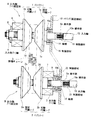
以下、本発明の実施上の最良の形態に係るチェーン式無段変速機を、添付図を参照して説明すると、図1は、同チェーン式無段変速機の構成図、図2は、図1の無段変速機の要部の拡大断面図、図3は、図1の無段変速機の一部である制振部材の分解斜視図である。 The chain type continuously variable transmission according to the best mode for carrying out the present invention will be described below with reference to the accompanying drawings. FIG. 1 is a block diagram of the chain type continuously variable transmission, and FIG. FIG. 3 is an exploded perspective view of a damping member that is a part of the continuously variable transmission of FIG. 1.
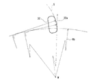
図1に示すチェーン式無段変速機は、入力側プーリ組立体Aと、出力側プーリ組立体Bとを備える。入力側プーリ組立体Aは、円錐台形状をなす固定円錐シーブ1aと可動円錐シーブ1bとからなるドライブプーリ1を備える。出力側プーリ組立体Bは、円錐台形状をなす固定円錐シーブ2aと可動円錐シーブ2bとからなるドリブンプーリ2を備える。ドライブプーリ1とドリブンプーリ2との間に無端チェーン3が巻き掛けられる。
The chain type continuously variable transmission shown in FIG. 1 includes an input side pulley assembly A and an output side pulley assembly B. The input side pulley assembly A includes a
ドライブプーリ1の固定円錐シーブ1aと可動円錐シーブ1bは、それぞれの円錐面1c,1dを向き合わせて両円錐面1c,1d間に無端チェーン3巻き掛け用のV字形周溝を形成した状態で、固定円錐シーブ1aは入力側プーリ軸4に軸方向不動に、可動円錐シーブ1bは入力側プーリ軸4にスプライン嵌合されて一体回転可能かつ軸方向変位可能に取り付けられており、これによって、ドライブプーリ1は、入力側プーリ軸4に一体回転可能に設けられている。
The fixed conical sheave 1a and the movable conical sheave 1b of the
ドリブンプーリ2の固定円錐シーブ2aと可動円錐シーブ2bは、それぞれの円錐面2c,2dを向き合わせて両円錐面1c,1d間に無端チェーン3巻き掛け用のV字形の周溝を形成した状態で、固定円錐シーブ2aは出力側プーリ軸5に軸方向不動に、可動円錐シーブ2bは出力側プーリ軸5にスプライン嵌合されて一体回転可能かつ軸方向変位可能に取り付けられており、これによって、ドリブンプーリ2は、入力側プーリ軸4に平行配置された出力側プーリ軸5に一体回転可能に設けられている。
The fixed conical sheave 2a and the movable conical sheave 2b of the driven pulley 2 face each
ドライブプーリ1において、その可動円錐シーブ1bの図1上左側となる背面側に、軸方向の推力を発生するアクチュエータ6が設けられている。アクチュエータ6の駆動により、可動円錐シーブ1bは、軸方向に無段階に変位し、その円錐面1dは固定円錐シーブ1aの円錐面1cとで形成する無端チェーン3巻き掛け用周溝の溝幅が無段階的に変更される。
In the
ドリブンプーリ2において、その可動円錐シーブ2bの図1上右側となる背面側に、軸方向の推力を発生するアクチュエータ7が設けられている。アクチュエータ7の駆動により、可動円錐シーブ2bは軸方向に無段階に変位し、その円錐面2dは固定円錐シーブ2aの円錐面2cとで形成する無端チェーン3の巻き掛け用周溝の溝幅が無段階に変更される。
In the driven pulley 2, an actuator 7 for generating axial thrust is provided on the back side of the movable conical sheave 2b on the right side in FIG. By driving the actuator 7, the movable conical sheave 2b is displaced stepwise in the axial direction, and the
以上のドライブプーリ1側およびドリブンプーリ2側それぞれの無端チェーン3の巻き掛け用周溝の溝幅の無段階変更に伴って無端チェーン3の巻き掛け径が無段階に変更されて無段階の変速が行われる。
With the stepless change of the groove width of the winding circumferential groove of the
アクチュエータ6,7としては、例えば、ボールねじ装置や油圧シリンダ、あるいは、入力側プーリ軸4や出力側プーリ軸5の回転に伴う遠心力を利用して軸方向の推力を発生する機構などとすることができる。各アクチュエータ6,7それぞれの一端は、入力側プーリ軸4および出力側プーリ軸5それぞれに設けられた受止め環8,9に受止められている。
The
アクチュエータ6は、アクチュエータ7とは逆動作するようになっており、アクチュエータ6が可動円錐シーブ1bを、無端チェーン3巻き掛け用周溝の溝幅を狭くする方向に変位させるときには、アクチュエータ7は、可動円錐シーブ2bを、無端チェーン3巻き掛け用周溝の溝幅を広くする方向に変位させる。
The
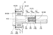
以上の構成を備えた無段変速機において、入力側プーリ軸4は、ハウジング(固定部材)10に、軸受11を介して相対回転可能に片持ち支持され、かつ、端部に備えた筒状のプーリ側継手部4aがエンジン側の入力軸13の端部に備えた入力軸側継手部13aに同軸にスプライン等で係合されている。そして、プーリ側継手部4aと入力軸側継手部13aとの係合面S1,S2間には制振部材15が介装されている。
In the continuously variable transmission having the above configuration, the input-
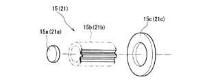
制振部材15は、入力側プーリ軸4から入力軸13への振動伝播を遮断するためのもので、入力側プーリ軸4と入力軸13との対向部に沿って一体に形成されてもよいが、本実施形態では、図3に明示するように、プーリ側継手部4aの内端面と入力軸側継手部13aの先端面との間に介装される円板部15aと、プーリ側継手部4aのスプラインと入力軸側継手部13aのスプラインとの間に介装されるスプライン部15bと、プーリ側継手部4aの先端面と入力軸側継手部13aの段落面との間に介装される環状円板部15cとに分割して形成されている。
The
制振部材15は、樹脂系、ゴム系、アスファルト系、金属系等の粘弾性材料からなる。金属系の材料には、Mn−Cu系合金、Ni−Ti系合金、Fe−Al系合金、ジュラルミン系等がある。Mn−Cu系合金は、制振性だけでなく成形性、加工性、非磁性等に優れている。Fe−Al系合金は高温制振性に優れている。樹脂系の材料には、フッ素系、シリコン系、ウレタン系、エステル系、アミド系等が挙げられる。
The damping
入力側プーリ軸4は、軸受11を介してハウジング10の筒部10aに相対回転可能に支持される。このハウジング10の筒部10aの内周面S3(固定面)と軸受10の外輪の外周面S4(被固定面)との間に、筒状の制振部材16が介装されている。この制振部材16は、上記制振部材15と同様の材料で構成される。
The input-
出力側プーリ軸5は、端部に備えた筒状のプーリ側継手部5aが出力軸19の端部に備えた出力軸側継手部19aに同軸にスプライン等で係合されている。そして、プーリ側継手部5aと出力軸側継手部19aとの係合面S5,S6間には制振部材21が介装されている。
The output-
制振部材21は、出力側プーリ軸5から出力軸19への振動伝播を遮断するためのもので、出力側プーリ軸5と出力軸19との対向部に沿って一体に形成されてもよいが、本実施形態では、図3に明示するように、プーリ側継手部5aの内端面と出力軸側継手部19aの先端面との間に介装される円板部21aと、プーリ側継手部5aのスプラインと出力軸側継手部19aとの間に介装されるスプライン部21bと、プーリ側継手部5aの先端面と出力軸側継手部19aの段落面との間に介装される環状円板部21cとに分割して形成されている。この制振部材21も、上記制振部材15と同様の材料で構成される。
The damping
入力側プーリ軸4と同様に、出力側プーリ軸5も、ハウジング(固定部材)10の筒部10bに、軸受17を介して相対回転可能に片持ち支持される。このハウジング10の筒部10bの内周面S7(固定面)と軸受17の外輪の外周面S8(被固定面)との間に、筒状の制振部材22が介装されている。この制振部材22も、上記制振部材15と同様の材料で構成される。
Similar to the input-
入力側プーリ軸4の軸受11による支持部に設ける制振部材16は、軸受11の内輪の内周面と入力側プーリ軸4との間に介装してもよいし、出力側プーリ軸5の軸受17による支持部に設ける制振部材21は、軸受17の内輪の内周面と出力側プーリ軸5との間に介装してもよい。
The damping
入力側プーリ軸4および出力側プーリ軸5は、図示例のように片持ち支持に限らず、軸方向両側に軸受を設けて、これら軸受により各軸4,5の両端部を回転可能に支持するようにしてもよい。その場合、各軸の軸受による支持部にそれぞれ制振部材を介装させることが望ましい。
The input-
次に、図4ないし図7を参照して、図1の無端チェーン3の構成部材を説明する。図4は無端チェーン3の部分平面図、図5は無端チェーン3の部分斜視図、図6は、無端チェーン3を構成するリンクの側面図、図7は、図6のリンクに挿通される第1ピンの側面図である。
Next, components of the
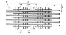
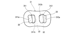
無端チェーン3は、長さ方向両端部に貫通孔311,312を有する複数のリンク31(31A,31B,31C)を、無端チェーン3の長さ方向L(図1では回送方向と同じ)にも幅方向Wにも配列して、第1ピン32と第2ピン33とにより、屈曲自在に連結したものである。なお、以下の説明では、各リンク31にある2個の貫通孔311,312のうち、無端チェーン3の回送方向Lの前方に位置する貫通孔311を前貫通孔、後方に位置する貫通孔312を後貫通孔という。
In the
リンク31は、複数のものを互いに間隔をおいて無端チェーンの幅方向Wに配列してリンク列(例えば、リンク31Aの列、リンク31Bの列)とし、このリンク列を複数、互いに無端チェーン3の長さ方向Lに位置をずらせて無端チェーン3の長さ方向Lに配列して、一のリンク列のリンク(例えば、31A)の後貫通孔312と他のリンク列のリンク(31Bもしくは31C)の前貫通孔311とを無端チェーン3の幅方向Wに整列対向させている。各貫通孔311,312には、第1ピン32および第2ピン33に対する固定部311a,312aと可動部311b,312bとが形成されている。
A plurality of
第1ピン32と第2ピン33とは、2本一組として互いに接触する状態で、無端チェーン3の幅方向Wに整列する貫通孔311,312に挿通されている。そして、第1ピン32は、一のリンク列のリンク31(例えば31A)の後貫通孔312の固定部312aに圧入により固定され、他のリンク列のリンク31(例えば31B)の前貫通孔311の可動部311b内に、第2ピン33の対向面と転がりもしくはすべり接触可能に挿通されている。これに対して、第2ピン33は、一のリンク列のリンク31(例えば31A)の後貫通孔312の可動部312b内に、第1ピン32の対向面と転がりもしくはすべり接触可能に挿通され、他のリンク列のリンク31(例えば31B)の前貫通孔311の固定部311aに圧入により固定されている。
The
第1と第2の両ピン32,33のうち、第2ピン33は、ストリップもしくはインターピースとして第1ピン32よりも僅かに短くされており、これにより、第1ピン32の外端面のみがプーリ1,2の円錐面1c,2c,1d,2dに摩擦接触可能になっている。第1ピン32の外端面は凸面形状を有し、無端チェーン3の引張力を摩擦力でプーリ1,2に伝達できるようになっている。
Of both the first and
第1と第2の両ピン32,33の組において、第1ピン32を基準とした場合、この第1ピン32と第2ピン33との接触位置の軌跡は、円のインボリュートSとされている。この実施形態では、第1ピン32の接触面32aが、図7に示すように、断面において半径Rb、中心Mの基礎円を持つインボリュート形状を有し、第2ピン33の接触面が平坦面(断面形状が直線)とされている。第1ピン32と第2ピン33との接触位置の軌跡からなるインボリュートSは、第1ピン32と第2ピン33の各組において一定ではなく、インボリュートSの基礎円半径が異なる2種以上のピンの組が用意されて、これらのピンの組が無端チェーン3の長さ方向Lに沿ってランダムに配置されている。
When the
これにより、各リンク31が無端チェーン3の回送経路の直線部分からプーリ1,2周りの円弧部分へ、また円弧部分から直線部分へ移行する際、前貫通孔311の可動部311bにおいて、第2ピン33が第1ピン32に対して転がり接触(厳密には、若干のすべり接触を含む)しながら回転し、後貫通孔312の可動部312bにおいては、第1ピン32が第2ピン33に対して転がり接触(厳密には、若干のすべり接触を含む)しながら回転する。
As a result, when each link 31 moves from the straight part of the routing path of the
図示の実施形態では、第1ピン32および第2ピン33のうち、長尺である第1ピン32の接触面をインボリュート形状とし、第2ピン33の接触面を平坦面としたが、短寸である第2ピン33の接触面をインボリュート形状としてもよく、また、第1ピン32および第2ピン33の各接触面をそれぞれ曲面に形成してもよく、要するに、第1ピン32と第2ピン33との接触位置の軌跡が円のインボリュートとなればよい。
In the illustrated embodiment, of the
また、図示の実施形態では、前貫通孔311と後貫通孔312とのピッチ(正確には、前貫通孔311での第1ピン32と第2ピン33との接触位置から、後貫通孔312での第1ピン32と第2ピン33との接触位置までのピッチ)が一定であるリンク31を用いたが、上記ピッチが異なる複数種類のリンクを用いてもよい。その場合、ピッチが大きいリンクについて、その貫通孔311,312に挿通されるピンの組に対して設定されるインボリュートの基礎円は、ピッチの小さなリンクの貫通孔311,312に挿通されるピンの組のインボリュートの基礎円より大きくするのが好ましい。
In the illustrated embodiment, the pitch between the front through-
A 入力側プーリ組立体
B 出力側プーリ組立体
1 ドライブプーリ
2 ドリブンプーリ
3 無端チェーン
4 入力側プーリ軸
4a プーリ側継手部
5 出力側プーリ軸
5a プーリ側継手部
10 ハウジング(固定部材)
13 入力軸
13a 入力軸側継手部
15 制振部材
16 制振部材
19 出力軸
19a 出力軸側継手部
21 制振部材
22 制振部材
A Input side pulley assembly B Output
13
Claims (2)
Each of the pulley assemblies includes a pulley shaft that is rotatably supported by a cylindrical portion of a housing as a fixed member via the bearing, a fixed conical sheave fixed to the pulley shaft, and a pulley shaft. The chain type continuously variable transmission according to claim 1, further comprising a movable conical sheave attached so as to be axially displaceable, wherein the pulley shaft includes the joint at an end thereof.
Priority Applications (1)
| Application Number | Priority Date | Filing Date | Title |
|---|---|---|---|
| JP2004102941A JP2005291235A (en) | 2004-03-31 | 2004-03-31 | Chain type continuously variable transmission |
Applications Claiming Priority (1)
| Application Number | Priority Date | Filing Date | Title |
|---|---|---|---|
| JP2004102941A JP2005291235A (en) | 2004-03-31 | 2004-03-31 | Chain type continuously variable transmission |
Publications (1)
| Publication Number | Publication Date |
|---|---|
| JP2005291235A true JP2005291235A (en) | 2005-10-20 |
Family
ID=35324414
Family Applications (1)
| Application Number | Title | Priority Date | Filing Date |
|---|---|---|---|
| JP2004102941A Pending JP2005291235A (en) | 2004-03-31 | 2004-03-31 | Chain type continuously variable transmission |
Country Status (1)
| Country | Link |
|---|---|
| JP (1) | JP2005291235A (en) |
Cited By (3)
| Publication number | Priority date | Publication date | Assignee | Title |
|---|---|---|---|---|
| CN100425872C (en) * | 2006-08-28 | 2008-10-15 | 上海中纺机通用机械有限公司 | Roller-type step-less speed variator containing shear-like lever plate |
| CN103968062A (en) * | 2013-02-04 | 2014-08-06 | 本田技研工业株式会社 | Control apparatus of continuously Variable Transmission |
| JP2015068375A (en) * | 2013-09-27 | 2015-04-13 | 日産自動車株式会社 | Bearing structure of endless winding transmission |
-
2004
- 2004-03-31 JP JP2004102941A patent/JP2005291235A/en active Pending
Cited By (4)
| Publication number | Priority date | Publication date | Assignee | Title |
|---|---|---|---|---|
| CN100425872C (en) * | 2006-08-28 | 2008-10-15 | 上海中纺机通用机械有限公司 | Roller-type step-less speed variator containing shear-like lever plate |
| CN103968062A (en) * | 2013-02-04 | 2014-08-06 | 本田技研工业株式会社 | Control apparatus of continuously Variable Transmission |
| CN103968062B (en) * | 2013-02-04 | 2016-05-11 | 本田技研工业株式会社 | The control device of buncher |
| JP2015068375A (en) * | 2013-09-27 | 2015-04-13 | 日産自動車株式会社 | Bearing structure of endless winding transmission |
Similar Documents
| Publication | Publication Date | Title |
|---|---|---|
| JP4667342B2 (en) | Endless belt for power transmission | |
| JP2009103151A (en) | Power transmission chain and power transmission device | |
| JP2005291235A (en) | Chain type continuously variable transmission | |
| US9765859B2 (en) | Serial continuously variable transmission | |
| JP2004504573A (en) | Belt type drive ring CVT coupler | |
| JP4335941B2 (en) | Belt type continuously variable transmission and pulley thereof | |
| JP2007270914A (en) | Power transmission chain and power transmission device including the same | |
| JP4761113B2 (en) | Power transmission chain and power transmission device including the same | |
| JP2008101747A (en) | Power transmission chain and power transmission device including the same | |
| JPH02173447A (en) | Continuously variable transmission | |
| JP5409449B2 (en) | Chain type continuously variable transmission | |
| JP2006077847A (en) | Power transmission chain and power transmission device including the same | |
| JP4591764B2 (en) | Power transmission chain and power transmission device including the same | |
| JP2005140225A (en) | Power transmission chain and power transmission device | |
| JP5532788B2 (en) | Power transmission device | |
| JP2008116010A (en) | Endless belt for power transmission | |
| JP2006144855A (en) | Power transmission chain and power transmission device including the same | |
| JP2009144751A (en) | Continuously variable transmission | |
| JP2005207514A (en) | Pulley for continuously variable transmission and continuously variable transmission | |
| JP4939040B2 (en) | Belt type continuously variable transmission | |
| JP5614019B2 (en) | Power transmission device | |
| JP2011069410A (en) | Power transmission device | |
| JP2004509303A (en) | Drive ring CVT coupler | |
| JP2008169879A (en) | Power transmission chain and power transmission device | |
| JP2007100736A (en) | Power transmission chain and power transmission device using the same |
Legal Events
| Date | Code | Title | Description |
|---|---|---|---|
| A621 | Written request for application examination |
Free format text: JAPANESE INTERMEDIATE CODE: A621 Effective date: 20070307 |
|
| A977 | Report on retrieval |
Free format text: JAPANESE INTERMEDIATE CODE: A971007 Effective date: 20090708 |
|
| A131 | Notification of reasons for refusal |
Free format text: JAPANESE INTERMEDIATE CODE: A131 Effective date: 20090818 |
|
| A02 | Decision of refusal |
Free format text: JAPANESE INTERMEDIATE CODE: A02 Effective date: 20100112 |