JP2005291234A - Rolling bearing - Google Patents
Rolling bearing Download PDFInfo
- Publication number
- JP2005291234A JP2005291234A JP2004102940A JP2004102940A JP2005291234A JP 2005291234 A JP2005291234 A JP 2005291234A JP 2004102940 A JP2004102940 A JP 2004102940A JP 2004102940 A JP2004102940 A JP 2004102940A JP 2005291234 A JP2005291234 A JP 2005291234A
- Authority
- JP
- Japan
- Prior art keywords
- press
- outer ring
- inner ring
- axial direction
- end side
- Prior art date
- Legal status (The legal status is an assumption and is not a legal conclusion. Google has not performed a legal analysis and makes no representation as to the accuracy of the status listed.)
- Pending
Links
- 238000005096 rolling process Methods 0.000 title 1
- 239000000725 suspension Substances 0.000 description 10
- 230000002093 peripheral effect Effects 0.000 description 7
- 239000006096 absorbing agent Substances 0.000 description 6
- 239000012212 insulator Substances 0.000 description 6
- 230000035939 shock Effects 0.000 description 6
- 229910000831 Steel Inorganic materials 0.000 description 3
- 239000010959 steel Substances 0.000 description 3
- 238000000034 method Methods 0.000 description 2
- 238000000926 separation method Methods 0.000 description 2
- 238000005452 bending Methods 0.000 description 1
- 230000037396 body weight Effects 0.000 description 1
- 239000004519 grease Substances 0.000 description 1
- 239000000314 lubricant Substances 0.000 description 1
- 229920003002 synthetic resin Polymers 0.000 description 1
- 239000000057 synthetic resin Substances 0.000 description 1
Images

Classifications
-
- F—MECHANICAL ENGINEERING; LIGHTING; HEATING; WEAPONS; BLASTING
- F16—ENGINEERING ELEMENTS AND UNITS; GENERAL MEASURES FOR PRODUCING AND MAINTAINING EFFECTIVE FUNCTIONING OF MACHINES OR INSTALLATIONS; THERMAL INSULATION IN GENERAL
- F16C—SHAFTS; FLEXIBLE SHAFTS; ELEMENTS OR CRANKSHAFT MECHANISMS; ROTARY BODIES OTHER THAN GEARING ELEMENTS; BEARINGS
- F16C33/00—Parts of bearings; Special methods for making bearings or parts thereof
- F16C33/30—Parts of ball or roller bearings
- F16C33/58—Raceways; Race rings
- F16C33/588—Races of sheet metal
-
- F—MECHANICAL ENGINEERING; LIGHTING; HEATING; WEAPONS; BLASTING
- F16—ENGINEERING ELEMENTS AND UNITS; GENERAL MEASURES FOR PRODUCING AND MAINTAINING EFFECTIVE FUNCTIONING OF MACHINES OR INSTALLATIONS; THERMAL INSULATION IN GENERAL
- F16C—SHAFTS; FLEXIBLE SHAFTS; ELEMENTS OR CRANKSHAFT MECHANISMS; ROTARY BODIES OTHER THAN GEARING ELEMENTS; BEARINGS
- F16C19/00—Bearings with rolling contact, for exclusively rotary movement
- F16C19/02—Bearings with rolling contact, for exclusively rotary movement with bearing balls essentially of the same size in one or more circular rows
- F16C19/04—Bearings with rolling contact, for exclusively rotary movement with bearing balls essentially of the same size in one or more circular rows for radial load mainly
- F16C19/06—Bearings with rolling contact, for exclusively rotary movement with bearing balls essentially of the same size in one or more circular rows for radial load mainly with a single row or balls
-
- F—MECHANICAL ENGINEERING; LIGHTING; HEATING; WEAPONS; BLASTING
- F16—ENGINEERING ELEMENTS AND UNITS; GENERAL MEASURES FOR PRODUCING AND MAINTAINING EFFECTIVE FUNCTIONING OF MACHINES OR INSTALLATIONS; THERMAL INSULATION IN GENERAL
- F16C—SHAFTS; FLEXIBLE SHAFTS; ELEMENTS OR CRANKSHAFT MECHANISMS; ROTARY BODIES OTHER THAN GEARING ELEMENTS; BEARINGS
- F16C19/00—Bearings with rolling contact, for exclusively rotary movement
- F16C19/02—Bearings with rolling contact, for exclusively rotary movement with bearing balls essentially of the same size in one or more circular rows
- F16C19/14—Bearings with rolling contact, for exclusively rotary movement with bearing balls essentially of the same size in one or more circular rows for both radial and axial load
- F16C19/16—Bearings with rolling contact, for exclusively rotary movement with bearing balls essentially of the same size in one or more circular rows for both radial and axial load with a single row of balls
- F16C19/163—Bearings with rolling contact, for exclusively rotary movement with bearing balls essentially of the same size in one or more circular rows for both radial and axial load with a single row of balls with angular contact
Landscapes
- Engineering & Computer Science (AREA)
- General Engineering & Computer Science (AREA)
- Mechanical Engineering (AREA)
- Rolling Contact Bearings (AREA)
Abstract
Description
本発明は、鋼板をプレス成形してなるプレス外輪およびプレス内輪を有するプレス形アンギュラ玉軸受に関する。このプレス形アンギュラ玉軸受は、例えば車両のサスペンションの上部に用いられる。 The present invention relates to a press-type angular contact ball bearing having a press outer ring and a press inner ring formed by press-forming a steel plate. This press-type angular ball bearing is used, for example, on the upper part of a vehicle suspension.
例えばストラット式サスペンションは、ショックアブソーバーの周囲にコイルスプリングを装着した構成であり、上部がストラットインシュレータを介して車体(ボディ)に支持され、下部がロアアームに支持される。このようなサスペンション用としての軸受は、車体側に固定されるストラットインシュレータと、コイルスプリングの上端を受けるアッパシートとの間に組み込まれる。この軸受は、プレス製の軌道輪を有するスラスト玉軸受が用いられる。このスラスト玉軸受は、鋼板をプレス成形してなる二つのレースを軸方向に対向配置し、両レース間に複数個の玉を斜めに接触させる状態で介装した構成である(例えば特許文献1参照。)。このスラスト玉軸受は、その各レースが軸方向に分離する構造であるために、取り扱いに注意が必要となる等、使用場所への取り付け作業が面倒になる。
そこで、本発明は、プレス形アンギュラ玉軸受において、部品点数を増やすことなくプレス外輪とプレス内輪とを非分離の構造とし、取り扱いを容易にすることを解決すべき課題とする。 Accordingly, an object of the present invention is to provide a press-type angular contact ball bearing having a non-separated structure between the press outer ring and the press inner ring without increasing the number of parts, and to facilitate handling.
本発明のプレス形アンギュラ玉軸受は、プレス外輪の軸方向一端側とプレス内輪の軸方向他端側とにそれぞれ設けられる湾曲斜面間に複数個の玉を介装し、作用線を回転軸線に対し傾かせたプレス形アンギュラ玉軸受であって、上記プレス外輪の軸方向他端側と上記プレス内輪の軸方向一端側とに、当該両輪が軸方向に相対変位したときにそれぞれ複数個の玉に対する軸方向への移動を制限する制限部を設け、この各制限部に、作用線が上記と逆向きに傾く補助外輪軌道面および補助内輪軌道面を設けたことを特徴とするものである。 The press-type angular contact ball bearing of the present invention has a plurality of balls interposed between curved inclined surfaces provided on one axial end side of the press outer ring and the other axial end side of the press inner ring, and the action line serves as the rotation axis. A press-type angular contact ball bearing tilted relative to the other end side in the axial direction of the outer press ring and one end side in the axial direction of the inner press ring when a plurality of balls are relatively displaced in the axial direction. A restricting portion for restricting movement in the axial direction with respect to is provided, and each restricting portion is provided with an auxiliary outer ring raceway surface and an auxiliary inner ring raceway surface in which the action line is inclined in the opposite direction.
本発明によると、プレス外輪とプレス内輪とが軸方向に相対的に変位したときに、プレス外輪の制限部とプレス内輪の制限部とが玉に引っ掛かって受け止められるので、プレス外輪とプレス内輪とが分離しない。しかも、両制限部には玉の補助的な軌道面を設けているので、プレス外輪の制限部およびプレス内輪の制限部が玉に当接したときに、その作用線がそれまでと逆向きの傾きになるものの、玉の円滑な転がり動作を可能とする等、軸受機能が確保される。このように、プレス外輪とプレス内輪とを非分離としたうえで、プレス外輪とプレス内輪とが軸方向にずれ動いた状態でもプレス外輪とプレス内輪との相対回転を円滑に転がり支持することが可能になる。 According to the present invention, when the press outer ring and the press inner ring are relatively displaced in the axial direction, the press outer ring restricting portion and the press inner ring restricting portion are caught by the ball and are received. Does not separate. In addition, since both the restricting portions are provided with an auxiliary raceway surface of the ball, when the restricting portion of the press outer ring and the restricting portion of the press inner ring abut on the ball, the action line is opposite to the previous one. Although it is inclined, the bearing function is ensured, such as enabling the ball to smoothly roll. As described above, the press outer ring and the press inner ring are not separated from each other, and the relative rotation between the press outer ring and the press inner ring can be smoothly rolled and supported even when the press outer ring and the press inner ring are displaced in the axial direction. It becomes possible.
本発明によると、部品点数を増やすことなくプレス外輪とプレス内輪とを非分離の構造とすることができ、取り扱いが容易となる。しかも、プレス外輪とプレス内輪とが軸方向に相対的に変位した状態でもプレス外輪とプレス内輪との相対回転を円滑に転がり支持することが可能になる。 According to the present invention, the press outer ring and the press inner ring can have a non-separated structure without increasing the number of parts, and the handling becomes easy. Moreover, even when the press outer ring and the press inner ring are relatively displaced in the axial direction, the relative rotation between the press outer ring and the press inner ring can be smoothly rolled and supported.
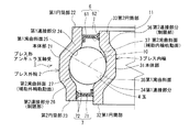
以下、本発明の最良の形態を図面を参照して説明する。図1は、プレス形アンギュラ玉軸受の片半分を示す断面図である。 The best mode of the present invention will be described below with reference to the drawings. FIG. 1 is a sectional view showing a half of a press-type angular contact ball bearing.
同図に示すプレス形アンギュラ玉軸受1は、径方向に同心状に配置されるプレス外輪2およびプレス内輪3と、両輪2,3間に転動自在に介装された複数個の玉4と、複数個の玉4を保持する保持器5とを備える。ここでのプレス形アンギュラ玉軸受1は保持器を用いない総玉軸受となっている。プレス外輪2およびプレス内輪3は、共に、例えばJIS規格のSPCCやSCM等で代表される鋼板をプレス加工することにより製作される。
A press-type angular ball bearing 1 shown in FIG. 1 includes a press
プレス外輪2は、円筒形の本体部21と、本体部21の軸方向一端側に連接される小径の第1円筒部22と、本体部21の軸方向他端側に連接され内径寸法が本体部21よりも小径でかつ第1円筒部22よりも大径とされた第2円筒部23とを有し、第1円筒部22側の第1連接部分24の内周に第1湾曲斜面(玉4の主外輪軌道面)25が設けられ、第2円筒部23側の第2連接部分(制限部)26の内周に第2湾曲斜面(玉4の補助外輪軌道面)27が設けられている。
The press
プレス内輪3は、円筒形の本体部31と、本体部31の軸方向他端側に連接される大径の第1円筒部32と、本体部31の軸方向一端側に連接され外径寸法が本体部31よりも大径でかつ第1円筒部32よりも小径とされた第2円筒部33とを有し、第1円筒部32側の第1連接部分34の外周に第1湾曲斜面(玉4の主内輪軌道面)35が設けられ、第2円筒部32側の第2連接部分(制限部)36の外周に第2湾曲斜面(玉4の補助外輪軌道面)37が設けられている。
The press
プレス外輪2の本体部21がプレス内輪3の本体部31に、また、プレス外輪2の第1円筒部22がプレス内輪3の第2円筒部33に、さらに、プレス外輪2の第2円筒部23がプレス内輪3の第1円筒部32に、それぞれ径方向で所定すきまを介して対向している。
The
玉4は、定常時にプレス外輪2の第1湾曲斜面25とプレス内輪3の第1湾曲斜面35とに接触されることで、プレス外輪2とプレス内輪3とに対し径方向斜めに接触されている。具体的に、玉4の作用線10は、当該玉軸受の回転軸線11を略鉛直方向に沿わせた状態で、図1上、上から下へ向かうに従い回転軸線11に近づくように傾いている。
The
そして、プレス外輪2の第1円筒部22の内周面とプレス内輪3の第1円筒部32の外周面とには、それぞれ、接触シール6,7が取り付けられている。この接触シール6,7は、それぞれ、芯金61,71に例えばゴムや合成樹脂等のシールリップ62,72を被着した構成である。接触シール6のシールリップ62は、プレス内輪3の第2円筒部33の外周面に接触され、接触シール7のシールリップ72は、プレス外輪2の第2円筒部23の内周面に接触されている。この接触シール6,7によって玉4が配置される当該玉軸受内部空間が外部から密封され、この密封された空間内に図示していないがグリース等の潤滑剤が収納される。
Contact
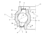
図2を参照して、プレス形アンギュラ玉軸受1の動きを説明する。例えば回転軸線11を鉛直方向に沿わせるとともにプレス内輪3の第1円筒部32を下にした状態において、プレス内輪3に鉛直方向下向きのアキシアル荷重が働いたとき、このプレス内輪3の第2連接部分36が制限部として玉4に引っ掛かって受け止められる。これによって、玉4がプレス内輪3と共に下へ動き、プレス外輪2の第2連接部分(制限部)26に引っ掛かるので、プレス内輪3は、上記下向きのアキシアル荷重が働いても、分離することはない。この状態では、玉4がプレス外輪2の第2湾曲斜面(補助外輪軌道面)27と、プレス内輪3の第2湾曲斜面(補助内輪軌道面)37とに接触し、それにより作用線10は、図1の傾きと逆向きに傾く。このとき、プレス形アンギュラ玉軸受1は鉛直方向下向きのアキシアル荷重を受ける状態になるから、プレス外輪2とプレス内輪3とが円滑に相対回転可能となる。
The movement of the press-type angular ball bearing 1 will be described with reference to FIG. For example, when a vertical downward axial load is applied to the press
このようなプレス形アンギュラ玉軸受1は、例えば公知の偏心組立方法で組み立てることができる。具体的に、プレス外輪2の内周側にプレス内輪3を挿入するとともに、プレス外輪2の内周側においてプレス内輪3を偏心させておき、これらプレス外輪2とプレス内輪3との対向部分において最も大きな対向すきま部分から複数個の玉4を順次挿入する。この偏心組立方法を実施し易くするために、プレス外輪2の第2円筒部23の内径寸法を、第1円筒部22の内径寸法よりも大きくし、また、プレス内輪3の第2円筒部33の最大外径寸法を、第1円筒部32の外径寸法よりも小さくしている。
Such a press-type angular ball bearing 1 can be assembled, for example, by a known eccentric assembly method. Specifically, the press
ところで、上述した構成のプレス形アンギュラ玉軸受1は、図3に示しているように、エアサスペンションの上部に用いられる。なお、エアサスペンションの基本的な一般構成は周知であるから、図3では、本発明に関わるエアサスペンションの要部の構成のみを示している。図に示すように、プレス形アンギュラ玉軸受1は、不図示の車体に取り付けられるインシュレータ15の内周にショックアブソーバのピストンロッド16を回転可能に支持させることに用いられる。具体的に、ピストンロッド16の段壁面16aの上に取り付けたアッパシート17およびカラー18と、ピストンロッド16の上端ねじ部16bに螺合されるナット19とによって、プレス内輪3を軸方向から挟むことにより、ピストンロッド16にプレス形アンギュラ玉軸受1を軸方向で位置決めしている。なお、プレス内輪3の第1円筒部32の端部がカラー18に、また、プレス内輪3の第2円筒部33の端部がナット19の座面にそれぞれ当接している。また、プレス形アンギュラ玉軸受1のプレス外輪2における第1連接部分24の外周部分をインシュレータ15の内周に設けられてあるインナースリーブ20の段差部20aに当接させ、インナースリーブ20の下端を径方向内向きに屈曲してプレス外輪2の下端面に当接させることによりプレス形アンギュラ玉軸受1をインシュレータ15に保持している。
By the way, the press-type angular contact ball bearing 1 having the above-described configuration is used in an upper portion of an air suspension as shown in FIG. Since the basic general configuration of the air suspension is well known, FIG. 3 shows only the configuration of the main part of the air suspension according to the present invention. As shown in the drawing, the press-type
ここで、不図示の車両の車輪を路面に接地した車両の通常使用状態では、車体重量がプレス外輪2に図3の矢印Xで示すように下向きのアキシアル荷重として働き、車体重量の車輪側からの反力がプレス内輪3に図3の矢印Yで示すように上向きのアキシアル荷重として働くので、プレス内輪3が分離することなく、プレス形アンギュラ玉軸受1がアキシアル荷重を負担する。
Here, in a normal use state of a vehicle in which the wheel of a vehicle (not shown) is grounded on the road surface, the vehicle body weight acts as a downward axial load on the press
しかし、例えば車両をリフトアップして車輪を路面から浮かせている状態では、不図示のショックアブソーバの重量がプレス内輪3に図3の矢印Zで示すように下向きのアキシアル荷重として働くので、プレス内輪3が前記ショックアブソーバと共に下がることになる。その場合、上述したように、プレス内輪3の第2連接部分36が玉4に引っ掛かって受け止められるとともに、玉4がプレス内輪3と共に下がり、プレス外輪2の第2連接部分26に引っ掛かるので、プレス内輪3が分離しない。この状態では、玉4がプレス外輪2の第2湾曲斜面27と、プレス内輪3の第2湾曲斜面37とに接触し、それにより作用線10が図3の傾きと逆向きに傾く。このとき、プレス形アンギュラ玉軸受1は下向きのアキシアル荷重を受ける状態になり、プレス外輪2とプレス内輪3とが円滑に相対回転しうるので、前記ショックアブソーバを回転可能に支えることができる。
However, for example, when the vehicle is lifted up and the wheels are lifted off the road surface, the weight of the shock absorber (not shown) acts as a downward axial load on the press
このように、プレス形アンギュラ玉軸受1を非分離構造としているので、その単体での搬送時や使用場所への着脱時における取り扱いが容易となり、好ましい。しかも、この非分離構造のプレス形アンギュラ玉軸受1をエアサスペンションの上部に用いた場合でも、インシュレータ15とショックアブソーバとが非分離となるので、取り扱いが容易となる。
Thus, since the press-type
本発明のプレス形アンギュラ玉軸受1は、エアサスペンションの他に適宜のストラット式サスペンションに用いることができる。
The press-type
1…プレス形アンギュラ玉軸受
2…プレス外輪
3…プレス内輪
4…玉
21…プレス外輪の本体部
22…プレス外輪の第1円筒部
23…プレス外輪の第2円筒部
24…プレス外輪の第1連接部分
25…プレス外輪の第1湾曲斜面(主内輪軌道面)
26…プレス外輪の第2連接部分(制限部)
27…プレス外輪の第2湾曲斜面(補助外輪軌道面)
31…プレス内輪の本体部
32…プレス内輪の第1円筒部
33…プレス内輪の第2円筒部
34…プレス内輪の第1連接部分
35…プレス内輪の第1湾曲斜面(主内輪軌道面)
36…プレス内輪の第2連接部分(制限部)
37…プレス内輪の第2湾曲斜面(補助内輪軌道面)
DESCRIPTION OF
26 ... Second connecting part of press outer ring (restriction part)
27: Second curved slope of the outer ring of press (auxiliary outer ring raceway surface)
DESCRIPTION OF
36 ... Second connecting part of press inner ring (restriction part)
37 ... Second curved slope of the inner ring of press (auxiliary inner ring raceway surface)
Claims (2)
上記プレス外輪の軸方向他端側と上記プレス内輪の軸方向一端側とに、当該両輪が軸方向に相対変位したときにそれぞれ複数個の玉に対する軸方向への移動を制限する制限部を設け、この各制限部に、作用線が上記と逆向きに傾く補助外輪軌道面および補助内輪軌道面を設けたことを特徴とするプレス形アンギュラ玉軸受。 A press-type angular contact ball bearing in which a plurality of balls are interposed between curved inclined surfaces provided on one end side of the press outer ring in the axial direction and the other end side in the axial direction of the press inner ring, and the action line is inclined with respect to the rotation axis. There,
A limiting portion is provided on the other axial end side of the outer press ring and on one axial end side of the inner press ring to restrict the movement of the plurality of balls in the axial direction when the wheels are relatively displaced in the axial direction. A press-type angular contact ball bearing characterized in that an auxiliary outer ring raceway surface and an auxiliary inner ring raceway surface in which the action line is inclined in the opposite direction to the above are provided in each of the restricting portions.
上記プレス内輪は、円筒形の本体部と、該本体部の軸方向他端側に連接される大径の第1円筒部と、該本体部の軸方向一端側に連接され外径寸法が本体部よりも大径でかつ第1円筒部よりも小径とされた第2円筒部とを有し、上記第1円筒部側の連接部分の外周に玉の主内輪軌道面となる湾曲斜面が設けられ、上記第2円筒部側の連接部分が上記制限部とされるとともに当該連接部分の外周に補助外輪軌道面となる湾曲斜面が設けられていることを特徴とする請求項1に記載のプレス形アンギュラ玉軸受。 The press outer ring includes a cylindrical main body portion, a small-diameter first cylindrical portion connected to one end side in the axial direction of the main body portion, and an inner diameter dimension connected to the other axial end side of the main body portion. And a curved inclined surface serving as a main outer ring raceway surface of the ball is provided on the inner periphery of the connecting portion on the first cylindrical portion side. The connecting portion on the second cylindrical portion side is the limiting portion, and a curved slope serving as an auxiliary outer ring raceway surface is provided on the inner periphery of the connecting portion,
The inner ring has a cylindrical main body, a first cylindrical portion having a large diameter connected to the other axial end of the main body, and an outer diameter dimension connected to one axial end of the main body. A curved slope that is the main inner ring raceway surface of the ball is provided on the outer periphery of the connecting portion on the first cylindrical portion side. 2. The press according to claim 1, wherein the connecting portion on the second cylindrical portion side is the restricting portion, and a curved inclined surface serving as an auxiliary outer ring raceway surface is provided on an outer periphery of the connecting portion. Angular contact ball bearings.
Priority Applications (1)
| Application Number | Priority Date | Filing Date | Title |
|---|---|---|---|
| JP2004102940A JP2005291234A (en) | 2004-03-31 | 2004-03-31 | Rolling bearing |
Applications Claiming Priority (1)
| Application Number | Priority Date | Filing Date | Title |
|---|---|---|---|
| JP2004102940A JP2005291234A (en) | 2004-03-31 | 2004-03-31 | Rolling bearing |
Publications (1)
| Publication Number | Publication Date |
|---|---|
| JP2005291234A true JP2005291234A (en) | 2005-10-20 |
Family
ID=35324413
Family Applications (1)
| Application Number | Title | Priority Date | Filing Date |
|---|---|---|---|
| JP2004102940A Pending JP2005291234A (en) | 2004-03-31 | 2004-03-31 | Rolling bearing |
Country Status (1)
| Country | Link |
|---|---|
| JP (1) | JP2005291234A (en) |
-
2004
- 2004-03-31 JP JP2004102940A patent/JP2005291234A/en active Pending
Similar Documents
| Publication | Publication Date | Title |
|---|---|---|
| JP5365557B2 (en) | Thrust slide bearing and combination mechanism of this thrust slide bearing and piston rod | |
| JP5029058B2 (en) | Thrust slide bearing and combination mechanism of this thrust slide bearing and piston rod | |
| JPH026279Y2 (en) | ||
| JP5157210B2 (en) | Thrust slide bearing and combination mechanism of this thrust slide bearing with piston rod and coil spring | |
| US9194431B2 (en) | Suspension thrust bearing device and suspension strut equipped with such a thrust bearing | |
| US8740233B2 (en) | Thrust sliding bearing and mounting structure of a strut-type suspension using the thrust sliding bearing | |
| JP5950623B2 (en) | Thrust sliding bearing and combination mechanism of thrust sliding bearing and piston rod | |
| CN102822542A (en) | Axial thrust bearing device with a mobile sealing ring | |
| US6814496B2 (en) | Suspension thrust bearing with retaining means | |
| JP2004245413A (en) | Suspension thrust bearing device | |
| CN106958592A (en) | synthetic resin sliding bearing | |
| US20180328404A1 (en) | Synthetic resin-made sliding bearing | |
| JP5328136B2 (en) | Wheel bearing | |
| JP2005291234A (en) | Rolling bearing | |
| JP2946268B2 (en) | Sealed thrust ball bearing | |
| JP4385823B2 (en) | Strut ball bearing | |
| JP2006162019A (en) | Strut thrust bearing and strut thrust bearing device | |
| JP2005291233A (en) | Angular ball bearing for suspension | |
| JP2008232174A (en) | Suspension bearing | |
| US7021612B2 (en) | Roller bearing | |
| JPH0645693Y2 (en) | Strut thrust bearing | |
| JP2006322505A (en) | Thrust bearing | |
| JP4940805B2 (en) | Thrust slide bearing and combination mechanism of this thrust slide bearing and piston rod | |
| JPS6246932Y2 (en) | ||
| JP2521950Y2 (en) | Bearing for strut type suspension |