JP2005291233A - Angular ball bearing for suspension - Google Patents
Angular ball bearing for suspension Download PDFInfo
- Publication number
- JP2005291233A JP2005291233A JP2004102939A JP2004102939A JP2005291233A JP 2005291233 A JP2005291233 A JP 2005291233A JP 2004102939 A JP2004102939 A JP 2004102939A JP 2004102939 A JP2004102939 A JP 2004102939A JP 2005291233 A JP2005291233 A JP 2005291233A
- Authority
- JP
- Japan
- Prior art keywords
- shoulder
- inner ring
- ring
- ball bearing
- suspension
- Prior art date
- Legal status (The legal status is an assumption and is not a legal conclusion. Google has not performed a legal analysis and makes no representation as to the accuracy of the status listed.)
- Pending
Links
Images

Landscapes
- Mounting Of Bearings Or Others (AREA)
- Rolling Contact Bearings (AREA)
Abstract
Description
本発明は、例えば車両のサスペンションに用いるアンギュラ玉軸受に関する。 The present invention relates to an angular ball bearing used, for example, in a vehicle suspension.
例えばストラット式サスペンションは、ショックアブソーバーの周囲にコイルスプリングを装着した構成であり、上部がストラットインシュレータを介して車体(ボディ)に支持され、下部がロアアームに支持される。このようなサスペンション用としての軸受は、車体側に固定されるストラットインシュレータと、コイルスプリングの上端を受けるアッパシートとの間に組み込まれる。この軸受は、プレス製の軌道輪を有するスラスト玉軸受が用いられる。このスラスト玉軸受は、鋼板をプレス成形してなる二つのレースを軸方向に対向配置し、両レース間に複数個の玉を斜めに接触させる状態で介装した構成である(例えば特許文献1参照。)。 For example, a strut suspension has a configuration in which a coil spring is mounted around a shock absorber, and an upper part is supported by a vehicle body (body) via a strut insulator and a lower part is supported by a lower arm. Such a suspension bearing is incorporated between a strut insulator fixed to the vehicle body side and an upper seat that receives the upper end of the coil spring. As this bearing, a thrust ball bearing having a press ring is used. This thrust ball bearing has a configuration in which two races formed by press-forming steel plates are arranged opposite to each other in the axial direction, and a plurality of balls are disposed in an oblique contact between both races (for example, Patent Document 1). reference.).
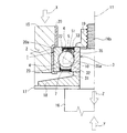
ところで、車体重量の比較的重い車両に使用する場合には、アキシアル負荷容量の比較的大きな転がり軸受を用いる必要がある。例えば車体重量の比較的重い車両に使用するサスペンションとして、例えばエアサスペンションがあり、このエアサスペンションは上記コイルスプリングに替えてエアスプリングを用いた構成である(例えば特許文献2参照。)。このようなエアサスペンションの上部に用いる転がり軸受には、削り加工で造った軌道輪を持つソリッド形の深溝玉軸受やアンギュラ玉軸受を用いることが考えられる。但し、深溝玉軸受の場合、アキシアル負荷容量が比較的小さい関係よりサイズの大きいタイプを用いなければならず、コスト的にも設置スペース的にも好ましくないので、アンギュラ玉軸受を用いるのが好ましい。このソリッド形のアンギュラ玉軸受をエアサスペンションに組み込んだ状態を、図7に示す。図中、81はショックアブソーバのピストンロッド、82は車体に取り付けられるインシュレータ、83は不図示のエアスプリングの上端を受けるアッパシート、84はアンギュラ玉軸受、85はナット、86はカラーである。アンギュラ玉軸受84は、軌道溝を有する外輪91と、肩おとし内輪92と、複数個の玉93と、保持器94とを備えた構成であり、回転軸線95を略鉛直方向に沿わせた姿勢にするとともに、肩おとし内輪92の正面を上に配置することにより、作用線96を上から下へ向かうに従い回転軸線95に近づけるような傾きにしている。また、肩おとし内輪92の肩おとし部92aの外径寸法は、玉93の内輪軌道となる外周斜面92bの最小径部の外径寸法と同じになっている。このようなアンギュラ玉軸受84では、肩おとし内輪92が軸方向に分離してしまうので、取り扱いに注意が必要となる等、作業が面倒になる。
そこで、本発明は、サスペンション用のアンギュラ玉軸受において、肩おとし内輪を非分離として、取り扱いを容易にできるようにすることを解決すべき課題とする。 SUMMARY OF THE INVENTION Accordingly, it is an object of the present invention to solve the problem that an angular ball bearing for a suspension can be handled easily by making the shoulder ring and the inner ring non-separable.
本発明のサスペンション用のアンギュラ玉軸受は、外輪と内輪との間に複数個の玉を斜接させた構成であり、かつサスペンションの上部に回転軸線が略鉛直方向に沿う姿勢で用いられるアンギュラ玉軸受であって、上記内輪を、肩おとし内輪とし、かつ、その肩おとし部に、玉または玉を保持する保持器の上記内輪に対する軸方向の移動を制限する制限部材に対する軸方向での引っ掛かりとなる制限部材を設けたことを特徴とするものである。 An angular contact ball bearing for a suspension according to the present invention has a configuration in which a plurality of balls are obliquely contacted between an outer ring and an inner ring, and an angular contact ball used in a posture in which a rotation axis is substantially along the vertical direction on the upper part of the suspension. A bearing, wherein the inner ring is a shoulder inner ring, and a ball or a retainer holding the ball is held on the shoulder base in an axial direction with respect to a restricting member that restricts axial movement of the inner ring with respect to the inner ring. The limiting member is provided.
なお、「回転軸線を略鉛直方向に沿わせる」という記載の「略」は、回転軸線が鉛直方向に対して一致する場合や、若干傾いた場合も含む意味で用いている。例えば肩おとし内輪の正面を上にした状態では、アンギュラ玉軸受の作用線が上から下へ向かうに従い回転軸線に近づくような傾きになる。 Note that “substantially” in the description “make the rotation axis substantially along the vertical direction” is used to include the case where the rotation axis coincides with the vertical direction and the case where the rotation axis is slightly inclined. For example, in a state where the front of the shoulder inner ring is facing up, the acting line of the angular ball bearing is inclined so as to approach the rotational axis as it goes from top to bottom.
本発明によると、例えば肩おとし内輪の正面を上にした状態で、肩おとし内輪に下向きのアキシアル荷重が働くと、この肩おとし内輪の制限部材が玉または保持器に引っ掛かって受け止められるので、肩おとし内輪が分離しない。 According to the present invention, for example, when a downward axial load is applied to the shoulder heel inner ring with the front surface of the shoulder heel inner ring facing upward, the shoulder rim inner ring restricting member is caught by the ball or the cage and is received. The inner ring does not separate.
好ましくは、上記制限部材を、上記内輪の肩おとし部に取り付けられる止め輪とし、この止め輪の外径寸法を保持器の内径寸法よりも大きくする。この場合、制限部材としての止め輪を外輪と肩おとし内輪と複数個の玉と保持器とを組み合わせた状態で、最終的に肩おとし内輪に取り付けるような組立作業が可能となるので、例えば外輪を焼き嵌めする等の手間を省くことができる。 Preferably, the restricting member is a retaining ring attached to the shoulder portion of the inner ring, and the outer diameter of the retaining ring is larger than the inner diameter of the cage. In this case, since the retaining ring as the restricting member can be assembled to the outer ring, the inner ring, the inner ring, the plurality of balls, and the cage, and finally attached to the inner ring of the shoulder, for example, the outer ring It is possible to save the trouble of shrink fitting.
好ましくは、上記制限部材を、上記内輪の肩おとし部に一体に形成される径方向外向きの隆起部とし、上記外輪を肩おとし外輪とし、かつ、その肩おとし部に玉の上記外輪に対する軸方向の移動を制限する制限部材を設け、上記外輪を、上記内輪に保持器で保持した複数個の玉を取り付けた組品に対し焼き嵌めにより組み付ける。この場合、制限部材としての隆起部を肩おとし内輪と一体に形成しているから、上記止め輪を用いる場合のように止め輪の取り付け作業を不要にできる。この場合、外輪を肩おとし外輪としなければ、この肩おとし外輪を、肩おとし内輪に保持器で保持した複数個の玉を取り付けた組品に対し組み付けることができない。そこで、外輪を肩おとし外輪として、その肩おとし部に制限部材を設けることで、それを上記組品に焼き嵌めにより組み付けできるようにしたうえで、肩おとし外輪の分離を防止するようにしている。 Preferably, the restricting member is a radially outwardly raised portion formed integrally with a shoulder skirt portion of the inner ring, the outer ring is a shoulder rim and an outer ring, and a ball shaft with respect to the outer ring is formed on the shoulder ridge portion. A restricting member for restricting the movement in the direction is provided, and the outer ring is assembled by shrink fitting to an assembly in which a plurality of balls held by a cage are attached to the inner ring. In this case, since the raised portion as the restricting member is formed integrally with the inner ring with the shoulder as a shoulder, it is possible to eliminate the need for attaching the retaining ring as in the case of using the retaining ring. In this case, if the outer ring is not a shoulder ring and an outer ring, the shoulder ring and outer ring cannot be assembled to an assembly in which a plurality of balls held by a cage are attached to the shoulder ring and the inner ring. Therefore, the outer ring is used as a shoulder ring and an outer ring, and a restriction member is provided on the shoulder collar part so that the outer ring can be assembled to the above assembly by shrink fitting, and separation of the shoulder ring and outer ring is prevented. .
本発明によれば、肩おとし内輪を非分離にしているので、使用場所への設置作業を容易に行うことができる。 According to the present invention, the shoulder and inner ring are not separated, so that the installation work at the place of use can be easily performed.
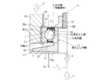
以下、本発明の最良の形態を図面を参照して説明する。図1は、例えばエアサスペンション用のソリッド形アンギュラ玉軸受の片半分を示す断面図である。なお、エアサスペンションの基本的な一般構成は周知であるから、図1では、本発明に関わるエアサスペンションの要部の構成のみを示している。 The best mode of the present invention will be described below with reference to the drawings. FIG. 1 is a cross-sectional view showing a half of a solid angular contact ball bearing for air suspension, for example. Since the basic general configuration of the air suspension is well known, FIG. 1 shows only the configuration of the main part of the air suspension according to the present invention.
同図に示すソリッド形アンギュラ玉軸受1は、径方向に同心状に配置される外輪2および肩おとし内輪3と、両輪2,3間に転動自在に介装された複数個の玉4と、複数個の玉4を保持する保持器5とを備える。外輪2および肩おとし内輪3は、共に、例えば軸受鋼等の金属を削り加工して製作されるものである。
The solid angular ball bearing 1 shown in FIG. 1 includes an
外輪2は、内周面に軌道溝21を有している。肩おとし内輪3は、軸方向一端側に径方向外向きに隆起して湾曲斜面32を形成する肩部31を有し、湾曲斜面32の最小径部から軸方向他端側にへ向けて軸方向に沿う肩おとし部33を有している。
The
玉4は、外輪2の軌道溝21と肩おとし内輪3の湾曲斜面32との間に介装され、外輪2と肩おとし内輪3とに対し斜めに接触されている。具体的に、玉4の作用線10は、肩おとし内輪3の正面を上にした状態で、上から下へ向かうに従い回転軸線11に近づくように傾いている。
The
保持器5は、冠型保持器とされており、環状本体部51が肩おとし内輪3の肩おとし部33側に配置されている。
The
そして、外輪2の両肩部には、接触シール6,7が取り付けられている。この接触シール6,7は、芯金(符号省略)に例えばゴムや合成樹脂等のシールリップ(符号省略)を被着した構成である。接触シール6,7のシールリップ(符号省略)が肩おとし内輪3の肩部31と肩おとし部33の外周面に接触される。この接触シール6,7によって玉4が配置される空間が外部から密封され、この密封された空間内に図示していないがグリース等の潤滑剤が収納される。
Contact
ここで、ソリッド形アンギュラ玉軸受1の肩おとし内輪3の肩おとし部33に、玉4の肩おとし内輪3に対する軸方向の移動を制限する制限部材として止め輪8が取り付けられている。この止め輪8は、スナップリング等であり、肩おとし内輪3の肩おとし部33に設けられている周溝34に係合されている。この止め輪8の外径寸法は、複数個の玉4の内接円径よりも大きくかつ保持器5の環状本体部51の内径寸法よりも小さく設定されている。このため、図2に示すように、肩おとし内輪3の正面を上にした状態において、肩おとし内輪3に下向きのアキシアル荷重が働いたとき、この肩おとし内輪3の止め輪8が玉4に引っ掛かって受け止められるので、肩おとし内輪3が分離することがない。
Here, a
なお、この実施形態のソリッド形アンギュラ玉軸受1の場合、次のようにして組み立てる必要がある。まず、外輪2に保持器5で保持した複数個の玉4を取り付けて組品とし、この組品に対し止め輪8を取り付けていない肩おとし内輪3を組み付ける。この後、肩おとし内輪3の周溝34に止め輪8を係合する。このように、制限部材として止め輪8を用いる場合には、外輪2を焼き嵌めする必要がなく、組立工程が簡単かつ迅速に行える等、製造コストダウンに貢献できる。
In addition, in the case of the solid angular ball bearing 1 of this embodiment, it is necessary to assemble as follows. First, a plurality of
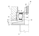
ところで、上述した構成のソリッド形アンギュラ玉軸受1は、図1に示しているように、エアサスペンションの上部に用いられる。つまり、ソリッド形アンギュラ玉軸受1は、不図示の車体に取り付けられるインシュレータ15の内周にショックアブソーバのピストンロッド16を回転可能に支持させることに用いられる。具体的に、ピストンロッド16の段壁面16aの上に取り付けたアッパシート17およびカラー18と、ピストンロッド16の上端ねじ部16bに螺合されるナット19とによって、肩おとし内輪3を軸方向から挟むことにより、ピストンロッド16にソリッド形アンギュラ玉軸受1を軸方向で位置決めしている。なお、肩おとし内輪3の背面がカラー18に、また、肩おとし内輪3の正面がナット19の座面にそれぞれ当接している。また、ソリッド形アンギュラ玉軸受1の外輪2の上端面をインシュレータ15の内周に設けられてあるインナースリーブ20の段差部20aに当接し、インナースリーブ20の下端を屈曲することによりソリッド形アンギュラ玉軸受1をインシュレータ15に保持している。
Incidentally, the solid angular ball bearing 1 having the above-described configuration is used in an upper portion of an air suspension, as shown in FIG. That is, the solid angular ball bearing 1 is used to rotatably support the
ここで、不図示の車両の車輪を路面に接地した車両の通常使用状態では、車体重量が外輪2に図1の矢印Xで示すように下向きのアキシアル荷重として働き、車体重量の車輪側からの反力が肩おとし内輪3に図1の矢印Yで示すように上向きのアキシアル荷重として働くので、肩おとし内輪3が分離することなく、ソリッド形アンギュラ玉軸受1がアキシアル荷重を負担する。
Here, in a normal use state of a vehicle in which the wheel of a vehicle (not shown) is in contact with the road surface, the vehicle body weight acts as a downward axial load on the
しかし、例えば車両をリフトアップして車輪を路面から浮かせている状態では、不図示のショックアブソーバの重量が肩おとし内輪3に図1の矢印Zで示すように下向きのアキシアル荷重として働くので、肩おとし内輪3が前記ショックアブソーバと共に下がることになる。その場合、上述したように、肩おとし内輪3の肩おとし部33に取り付けている止め輪8が玉4に引っ掛かるので、肩おとし内輪3の分離を防止できるとともに、前記ショックアブソーバを支えることができる。
However, for example, in the state where the vehicle is lifted up and the wheels are lifted from the road surface, the weight of the shock absorber (not shown) acts as a downward axial load on the
このように、ソリッド形アンギュラ玉軸受1を非分離構造としているので、その単体での搬送時や使用場所への着脱時における取り扱いが容易となり、好ましい。しかも、この非分離構造のソリッド形アンギュラ玉軸受1をエアサスペンションの上部に用いた場合でも、インシュレータ15とショックアブソーバとが非分離となるので、取り扱いが容易となる。
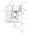
(他の実施形態)
図3および図4を参照して、本発明の他の実施形態を説明する。上記止め輪8の外径寸法を保持器5の環状本体部51の内径寸法よりも大きくしている。この場合、図4に示すように、肩おとし内輪3の正面を上にした状態において、肩おとし内輪3に下向きのアキシアル荷重が働いたとき、この肩おとし内輪3の止め輪8が保持器5に引っ掛かって受け止められるので、肩おとし内輪3は分離しない。なお、この実施形態では、肩おとし内輪3に下向きのアキシアル荷重が働いたときに止め輪8が保持器5に当接して玉4に当接しないので、玉4が損傷しない。
(他の実施形態)
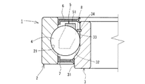
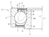
図5および図6を参照して、本発明の他の実施形態を説明する。肩おとし内輪3の肩おとし部33に、玉4の肩おとし内輪3に対する軸方向の移動を制限する制限部材として径方向外向きに隆起する隆起部35を設けている。この隆起部35の外径寸法を、複数個の玉4の内接円径よりも大きくかつ保持器5の環状本体部51の内径寸法よりも小さくしている。また、隆起部35の内側面を湾曲斜面35aとし、この湾曲斜面35aの曲率を玉4の曲率とほぼ同じにしている。これにより、隆起部35が玉4に当接したときに玉4が損傷しにくくなる。さらに、外輪2を肩おとし外輪とするとともに、この肩おとし外輪2の背面を上に配置している。この肩おとし外輪2の肩おとし部23は、その内径寸法を外輪軌道部21の最小径部よりも若干大きくすることによりこの肩おとし部23そのものを玉4に対する軸方向での引っ掛かりとなる制限部材としている。この肩おとし外輪2を用いる場合、ソリッド形アンギュラ玉軸受1の組み立て手順としては、まず、肩おとし内輪3に保持器5で保持した複数個の玉4を取り付けて組品とし、この組品に対し肩おとし外輪2を焼き嵌めにより組み付ける必要がある。
As described above, the solid
(Other embodiments)
With reference to FIGS. 3 and 4, another embodiment of the present invention will be described. The outer diameter of the retaining
(Other embodiments)
Another embodiment of the present invention will be described with reference to FIGS. A
この実施形態のソリッド形アンギュラ玉軸受1では、図6に示すように、肩おとし内輪3の正面を上にするとともに、肩おとし外輪2の背面を上にした状態において、肩おとし内輪3に下向きのアキシアル荷重が働いたとき、この肩おとし内輪3の隆起部35が玉4に引っ掛かって受け止められるので、肩おとし内輪3が分離しない。なお、肩おとし外輪2は、その肩部22と肩おとし部23とが玉4に対する軸方向での引っ掛かりとなるので、この肩おとし外輪2も分離しない。
In the solid-type angular
本発明のソリッド形アンギュラ玉軸受1は、エアサスペンションの他に適宜のストラット式サスペンションに用いることができる。
The solid
1…ソリッド形アンギュラ玉軸受、2…外輪、3…肩おとし内輪、4…玉、5…保持器、8…止め輪(制限部材)、15…インシュレータ、16…ピストンロッド、17…アッパシート、31…肩おとし内輪の肩部、32…肩おとし内輪の湾曲斜面、33…肩おとし内輪の肩おとし部。
DESCRIPTION OF
Claims (3)
上記内輪を、肩おとし内輪とし、かつ、その肩おとし部に、玉または玉を保持する保持器の上記内輪に対する軸方向の移動を制限する制限部材を設けたことを特徴とするサスペンション用のアンギュラ玉軸受。 An angular contact ball bearing for suspension that has a configuration in which a plurality of balls are obliquely contacted between an outer ring and an inner ring, and is used in a posture in which the rotation axis is substantially along the vertical direction on the upper part of the suspension,
An angular for suspension, wherein the inner ring is a shoulder inner ring, and a restricting member for restricting movement of the ball or a retainer for holding the ball in the axial direction with respect to the inner ring is provided on the shoulder base portion. Ball bearing.
Priority Applications (1)
| Application Number | Priority Date | Filing Date | Title |
|---|---|---|---|
| JP2004102939A JP2005291233A (en) | 2004-03-31 | 2004-03-31 | Angular ball bearing for suspension |
Applications Claiming Priority (1)
| Application Number | Priority Date | Filing Date | Title |
|---|---|---|---|
| JP2004102939A JP2005291233A (en) | 2004-03-31 | 2004-03-31 | Angular ball bearing for suspension |
Publications (1)
| Publication Number | Publication Date |
|---|---|
| JP2005291233A true JP2005291233A (en) | 2005-10-20 |
Family
ID=35324412
Family Applications (1)
| Application Number | Title | Priority Date | Filing Date |
|---|---|---|---|
| JP2004102939A Pending JP2005291233A (en) | 2004-03-31 | 2004-03-31 | Angular ball bearing for suspension |
Country Status (1)
| Country | Link |
|---|---|
| JP (1) | JP2005291233A (en) |
Cited By (3)
| Publication number | Priority date | Publication date | Assignee | Title |
|---|---|---|---|---|
| JP2009520937A (en) * | 2005-12-23 | 2009-05-28 | シエフレル・コマンデイトゲゼルシヤフト | Radial rolling bearings, especially single row spherical roller bearings |
| EP2458235A2 (en) | 2010-11-25 | 2012-05-30 | Aktiebolaget SKF | Angular contact ball bearing |
| US9041058B2 (en) | 2006-12-11 | 2015-05-26 | Sony Corporation | Metal oxide semiconductor having epitaxial source drain regions and method of manufacturing same using dummy gate process |
-
2004
- 2004-03-31 JP JP2004102939A patent/JP2005291233A/en active Pending
Cited By (12)
| Publication number | Priority date | Publication date | Assignee | Title |
|---|---|---|---|---|
| JP2009520937A (en) * | 2005-12-23 | 2009-05-28 | シエフレル・コマンデイトゲゼルシヤフト | Radial rolling bearings, especially single row spherical roller bearings |
| US9041058B2 (en) | 2006-12-11 | 2015-05-26 | Sony Corporation | Metal oxide semiconductor having epitaxial source drain regions and method of manufacturing same using dummy gate process |
| US9419096B2 (en) | 2006-12-11 | 2016-08-16 | Sony Corporation | Metal oxide semiconductor having epitaxial source drain regions and a method of manufacturing same using dummy gate process |
| US9502529B2 (en) | 2006-12-11 | 2016-11-22 | Sony Corporation | Metal oxide semiconductor having epitaxial source drain regions and a method of manufacturing same using dummy gate process |
| US9673326B2 (en) | 2006-12-11 | 2017-06-06 | Sony Corporation | Metal oxide semiconductor having epitaxial source drain regions and a method of manufacturing same using dummy gate process |
| US9865733B2 (en) | 2006-12-11 | 2018-01-09 | Sony Corporation | Metal oxide semiconductor having epitaxial source drain regions and a method of manufacturing same using dummy gate process |
| US10128374B2 (en) | 2006-12-11 | 2018-11-13 | Sony Corporation | Metal oxide semiconductor having epitaxial source drain regions and a method of manufacturing same using dummy gate process |
| US10868176B2 (en) | 2006-12-11 | 2020-12-15 | Sony Corporation | Metal oxide semiconductor having epitaxial source drain regions and a method of manufacturing same using dummy gate process |
| US11404573B2 (en) | 2006-12-11 | 2022-08-02 | Sony Group Corporation | Metal oxide semiconductor having epitaxial source drain regions and a method of manufacturing same using dummy gate process |
| US11901454B2 (en) | 2006-12-11 | 2024-02-13 | Sony Group Corporation | Metal oxide semiconductor having epitaxial source drain regions and a method of manufacturing same using dummy gate process |
| EP2458235A2 (en) | 2010-11-25 | 2012-05-30 | Aktiebolaget SKF | Angular contact ball bearing |
| DE102010061930A1 (en) * | 2010-11-25 | 2012-05-31 | Aktiebolaget Skf | Angular contact ball bearings |
Similar Documents
| Publication | Publication Date | Title |
|---|---|---|
| JP5365557B2 (en) | Thrust slide bearing and combination mechanism of this thrust slide bearing and piston rod | |
| JP5157210B2 (en) | Thrust slide bearing and combination mechanism of this thrust slide bearing with piston rod and coil spring | |
| JP5029058B2 (en) | Thrust slide bearing and combination mechanism of this thrust slide bearing and piston rod | |
| EP3385554B1 (en) | Synthetic resin thrust sliding bearing | |
| JPH026279Y2 (en) | ||
| US20060156511A1 (en) | Caster | |
| US20120251024A1 (en) | Ball Bearing and Corresponding Bump Stop | |
| JP2006513374A (en) | Plastic ring bearings especially for use in McPherson struts | |
| US10422374B2 (en) | Synthetic resin-made sliding bearing | |
| JP5328136B2 (en) | Wheel bearing | |
| JP2005291233A (en) | Angular ball bearing for suspension | |
| EP3372857B1 (en) | Synthetic resin slide bearing | |
| JP2008014463A (en) | Thrust sliding bearing, and thrust sliding bearing and piston rod combined mechanism | |
| JP4385823B2 (en) | Strut ball bearing | |
| CN215110060U (en) | Long-life plane bearing for vehicle suspension | |
| JP6968044B2 (en) | Bearing device for wheels | |
| JP2006322505A (en) | Thrust bearing | |
| US20130301968A1 (en) | Hub spindle bearing unit for wheel | |
| JP2005291234A (en) | Rolling bearing | |
| CN222772522U (en) | A suspension bearing suitable for complex working conditions | |
| CN112797082B (en) | Spring shock absorber bearing | |
| JPS6035795Y2 (en) | thrust bearing | |
| JP2005233304A (en) | Ball bearing for strut | |
| JPH0645693Y2 (en) | Strut thrust bearing | |
| JP2010069906A (en) | Thrust bearing |
Legal Events
| Date | Code | Title | Description |
|---|---|---|---|
| A621 | Written request for application examination |
Free format text: JAPANESE INTERMEDIATE CODE: A621 Effective date: 20070307 |
|
| A977 | Report on retrieval |
Effective date: 20090226 Free format text: JAPANESE INTERMEDIATE CODE: A971007 |
|
| A131 | Notification of reasons for refusal |
Effective date: 20090303 Free format text: JAPANESE INTERMEDIATE CODE: A131 |
|
| A02 | Decision of refusal |
Effective date: 20090630 Free format text: JAPANESE INTERMEDIATE CODE: A02 |