JP2005291212A - Ceramic-based bushing for variable-pitch vane system in turbomachine - Google Patents
Ceramic-based bushing for variable-pitch vane system in turbomachine Download PDFInfo
- Publication number
- JP2005291212A JP2005291212A JP2005107283A JP2005107283A JP2005291212A JP 2005291212 A JP2005291212 A JP 2005291212A JP 2005107283 A JP2005107283 A JP 2005107283A JP 2005107283 A JP2005107283 A JP 2005107283A JP 2005291212 A JP2005291212 A JP 2005291212A
- Authority
- JP
- Japan
- Prior art keywords
- bushing
- ceramic
- pivot
- turbomachine
- brazing
- Prior art date
- Legal status (The legal status is an assumption and is not a legal conclusion. Google has not performed a legal analysis and makes no representation as to the accuracy of the status listed.)
- Granted
Links
- 239000000919 ceramic Substances 0.000 title claims abstract description 30
- 238000005219 brazing Methods 0.000 claims abstract description 18
- 229910052751 metal Inorganic materials 0.000 claims abstract description 13
- 239000002184 metal Substances 0.000 claims abstract description 13
- XEEYBQQBJWHFJM-UHFFFAOYSA-N Iron Chemical compound [Fe] XEEYBQQBJWHFJM-UHFFFAOYSA-N 0.000 claims description 12
- PXHVJJICTQNCMI-UHFFFAOYSA-N Nickel Chemical compound [Ni] PXHVJJICTQNCMI-UHFFFAOYSA-N 0.000 claims description 12
- 239000010941 cobalt Substances 0.000 claims description 6
- 229910017052 cobalt Inorganic materials 0.000 claims description 6
- GUTLYIVDDKVIGB-UHFFFAOYSA-N cobalt atom Chemical compound [Co] GUTLYIVDDKVIGB-UHFFFAOYSA-N 0.000 claims description 6
- 229910052742 iron Inorganic materials 0.000 claims description 6
- 229910052759 nickel Inorganic materials 0.000 claims description 6
- 238000003780 insertion Methods 0.000 claims description 4
- 230000037431 insertion Effects 0.000 claims description 4
- 239000007769 metal material Substances 0.000 claims description 2
- 230000007547 defect Effects 0.000 abstract 1
- 239000000463 material Substances 0.000 description 10
- 239000000956 alloy Substances 0.000 description 2
- 229910045601 alloy Inorganic materials 0.000 description 2
- 238000009434 installation Methods 0.000 description 2
- 238000002844 melting Methods 0.000 description 2
- 230000008018 melting Effects 0.000 description 2
- 230000009466 transformation Effects 0.000 description 2
- 239000004642 Polyimide Substances 0.000 description 1
- 229910000831 Steel Inorganic materials 0.000 description 1
- RTAQQCXQSZGOHL-UHFFFAOYSA-N Titanium Chemical compound [Ti] RTAQQCXQSZGOHL-UHFFFAOYSA-N 0.000 description 1
- PNEYBMLMFCGWSK-UHFFFAOYSA-N aluminium oxide Inorganic materials [O-2].[O-2].[O-2].[Al+3].[Al+3] PNEYBMLMFCGWSK-UHFFFAOYSA-N 0.000 description 1
- 238000005452 bending Methods 0.000 description 1
- 230000001627 detrimental effect Effects 0.000 description 1
- 239000000314 lubricant Substances 0.000 description 1
- 230000001050 lubricating effect Effects 0.000 description 1
- 238000000034 method Methods 0.000 description 1
- 229920001721 polyimide Polymers 0.000 description 1
- 230000000717 retained effect Effects 0.000 description 1
- 239000010959 steel Substances 0.000 description 1
- 239000010936 titanium Substances 0.000 description 1
- 229910052719 titanium Inorganic materials 0.000 description 1
Images


Classifications
-
- F—MECHANICAL ENGINEERING; LIGHTING; HEATING; WEAPONS; BLASTING
- F16—ENGINEERING ELEMENTS AND UNITS; GENERAL MEASURES FOR PRODUCING AND MAINTAINING EFFECTIVE FUNCTIONING OF MACHINES OR INSTALLATIONS; THERMAL INSULATION IN GENERAL
- F16C—SHAFTS; FLEXIBLE SHAFTS; ELEMENTS OR CRANKSHAFT MECHANISMS; ROTARY BODIES OTHER THAN GEARING ELEMENTS; BEARINGS
- F16C33/00—Parts of bearings; Special methods for making bearings or parts thereof
- F16C33/02—Parts of sliding-contact bearings
- F16C33/04—Brasses; Bushes; Linings
- F16C33/043—Sliding surface consisting mainly of ceramics, cermets or hard carbon, e.g. diamond like carbon [DLC]
-
- F—MECHANICAL ENGINEERING; LIGHTING; HEATING; WEAPONS; BLASTING
- F01—MACHINES OR ENGINES IN GENERAL; ENGINE PLANTS IN GENERAL; STEAM ENGINES
- F01D—NON-POSITIVE DISPLACEMENT MACHINES OR ENGINES, e.g. STEAM TURBINES
- F01D17/00—Regulating or controlling by varying flow
- F01D17/10—Final actuators
- F01D17/12—Final actuators arranged in stator parts
- F01D17/14—Final actuators arranged in stator parts varying effective cross-sectional area of nozzles or guide conduits
- F01D17/16—Final actuators arranged in stator parts varying effective cross-sectional area of nozzles or guide conduits by means of nozzle vanes
- F01D17/162—Final actuators arranged in stator parts varying effective cross-sectional area of nozzles or guide conduits by means of nozzle vanes for axial flow, i.e. the vanes turning around axes which are essentially perpendicular to the rotor centre line
-
- F—MECHANICAL ENGINEERING; LIGHTING; HEATING; WEAPONS; BLASTING
- F05—INDEXING SCHEMES RELATING TO ENGINES OR PUMPS IN VARIOUS SUBCLASSES OF CLASSES F01-F04
- F05C—INDEXING SCHEME RELATING TO MATERIALS, MATERIAL PROPERTIES OR MATERIAL CHARACTERISTICS FOR MACHINES, ENGINES OR PUMPS OTHER THAN NON-POSITIVE-DISPLACEMENT MACHINES OR ENGINES
- F05C2201/00—Metals
- F05C2201/04—Heavy metals
- F05C2201/0433—Iron group; Ferrous alloys, e.g. steel
- F05C2201/0463—Cobalt
-
- F—MECHANICAL ENGINEERING; LIGHTING; HEATING; WEAPONS; BLASTING
- F05—INDEXING SCHEMES RELATING TO ENGINES OR PUMPS IN VARIOUS SUBCLASSES OF CLASSES F01-F04
- F05C—INDEXING SCHEME RELATING TO MATERIALS, MATERIAL PROPERTIES OR MATERIAL CHARACTERISTICS FOR MACHINES, ENGINES OR PUMPS OTHER THAN NON-POSITIVE-DISPLACEMENT MACHINES OR ENGINES
- F05C2201/00—Metals
- F05C2201/04—Heavy metals
- F05C2201/0433—Iron group; Ferrous alloys, e.g. steel
- F05C2201/0466—Nickel
-
- F—MECHANICAL ENGINEERING; LIGHTING; HEATING; WEAPONS; BLASTING
- F05—INDEXING SCHEMES RELATING TO ENGINES OR PUMPS IN VARIOUS SUBCLASSES OF CLASSES F01-F04
- F05D—INDEXING SCHEME FOR ASPECTS RELATING TO NON-POSITIVE-DISPLACEMENT MACHINES OR ENGINES, GAS-TURBINES OR JET-PROPULSION PLANTS
- F05D2230/00—Manufacture
- F05D2230/20—Manufacture essentially without removing material
- F05D2230/23—Manufacture essentially without removing material by permanently joining parts together
- F05D2230/232—Manufacture essentially without removing material by permanently joining parts together by welding
- F05D2230/237—Brazing
-
- F—MECHANICAL ENGINEERING; LIGHTING; HEATING; WEAPONS; BLASTING
- F05—INDEXING SCHEMES RELATING TO ENGINES OR PUMPS IN VARIOUS SUBCLASSES OF CLASSES F01-F04
- F05D—INDEXING SCHEME FOR ASPECTS RELATING TO NON-POSITIVE-DISPLACEMENT MACHINES OR ENGINES, GAS-TURBINES OR JET-PROPULSION PLANTS
- F05D2300/00—Materials; Properties thereof
- F05D2300/20—Oxide or non-oxide ceramics
- F05D2300/21—Oxide ceramics
-
- F—MECHANICAL ENGINEERING; LIGHTING; HEATING; WEAPONS; BLASTING
- F05—INDEXING SCHEMES RELATING TO ENGINES OR PUMPS IN VARIOUS SUBCLASSES OF CLASSES F01-F04
- F05D—INDEXING SCHEME FOR ASPECTS RELATING TO NON-POSITIVE-DISPLACEMENT MACHINES OR ENGINES, GAS-TURBINES OR JET-PROPULSION PLANTS
- F05D2300/00—Materials; Properties thereof
- F05D2300/40—Organic materials
- F05D2300/43—Synthetic polymers, e.g. plastics; Rubber
- F05D2300/434—Polyimides, e.g. AURUM
Abstract
Description
本発明は、円滑な軸受けを作るためのセラミックベースのブッシングに関する。 The present invention relates to a ceramic-based bushing for making smooth bearings.
より詳細には、本発明は、可変ピッチベーンのピボットのための円滑な軸受けを構成するために、ターボ機械ケーシングにおける貫通開口部内に取り付けられるセラミックベースのブッシングに関する。 More particularly, the present invention relates to a ceramic-based bushing that is mounted in a through opening in a turbomachine casing to provide a smooth bearing for the pivot of a variable pitch vane.
ターボ機械の、特にターボジェットのコンプレッサにおいて、1セット以上のステータベーンは、可変ピッチであり得る。すなわちそのようなベーンの迎え角が、サーボ制御システムの制御のもとで飛行条件に応じて変化されることができ、サーボ制御システムは、所定のセットにおけるベーンのピボットに対するリンクを介して結合されるバンドを移動させて、バンドを予め決められたパラメータに応じて回転させ且つ軸方向に移動させる。ケーシングの振動に関連する、ベーンピッチにおけるそのような変化は、接触部品の摩損を導く。摩損は、特に、角度オフセットが小さく且つ振動の周波数が160ヘルツ(Hz)の近傍であるときに、増大することがわかっている。最も有害な要素は、ピボットにおけるピーニング圧力であり、ピーニング圧力は、部品の強度に対して有害である。 In turbomachines, particularly turbojet compressors, one or more sets of stator vanes may be of variable pitch. That is, the angle of attack of such vanes can be varied according to flight conditions under the control of the servo control system, which is coupled via a link to the vane pivot in a given set. The band is moved, and the band is rotated according to a predetermined parameter and moved in the axial direction. Such changes in the vane pitch, associated with casing vibration, lead to wear of the contact parts. Wear has been found to increase, especially when the angular offset is small and the frequency of vibration is in the vicinity of 160 hertz (Hz). The most harmful factor is the peening pressure at the pivot, which is detrimental to the strength of the part.
ターボ機械における可変ピッチシステムについては、非潤滑媒体で動作させる必要によって構成される特別な制約がある。ドライルーブのみが、接触条件を改善し且つ部品の寿命を増長することが予想され得る。 For variable pitch systems in turbomachines, there are special constraints configured by the need to operate with non-lubricating media. Only dry lubes can be expected to improve contact conditions and increase part life.
それらの必要性を満足すべく、2003年1月16日に出願され、且つ仏国特許第2850138号公報として2004年7月23日に発行された、仏国特許出願公開第03/00435号において、本出願人は、その内部に、鉄、ニッケル、またはコバルトに基づくピボット、あるいは鉄、ニッケル、またはコバルトに基づく焼きばめインサートを有する金属ピボットが、ベーンピボットと円滑な軸受けとの間の連続的な接触の間に作られ、潤滑剤として作用する鉄、ニッケル、またはコバルトの酸化物を伴って配置された、セラミックブッシングを備える円滑な軸受けを提案している。 In order to satisfy those needs, in French Patent Application Publication No. 03/00435, filed on January 16, 2003 and issued on July 23, 2004 as French Patent No. 2850138. The Applicant has in its interior a pivot based on iron, nickel or cobalt, or a metal pivot with a shrink fit insert based on iron, nickel or cobalt, between the vane pivot and the smooth bearing. Proposes a smooth bearing with a ceramic bushing, made during normal contact and arranged with an oxide of iron, nickel or cobalt acting as a lubricant.
ブッシングを作るための材料としてのセラミックの使用を制限する要素の1つは、それらの脆性およびそれらの低い靭性である。それゆえ、ケーシングに取り付けられる間に、さもなければ動作中に、ケーシングの金属とセラミックとの間の異なる膨張係数に起因して、およびシステムによって受け入れられる衝撃に起因して、ブッシングが壊れるということが起こる。
本発明の目的とするところは、上述された欠点を軽減するセラミックブッシングを提案することにある。 The aim of the present invention is to propose a ceramic bushing which alleviates the drawbacks mentioned above.
本発明によれば、この目的は、ブッシングが、金属ジャケットと、前記金属ジャケットの内側壁部にろう付けによって固着されるセラミックリングとによって構成されるという事実によって達成される。 According to the invention, this object is achieved by the fact that the bushing is constituted by a metal jacket and a ceramic ring which is fixed to the inner wall of the metal jacket by brazing.
金属ジャケットは、ブッシングを、それがケーシングに取り付けられている間に強化し、それによって動作中における破損を低減する。セラミックリングに何らかのクラックが存在している場合には、部品は、ろう付けによって金属ジャケットに固着されたままである。加えて、ろう付けは、異なる膨張係数を有する2つの材料間の界面として作用し、且つ膨張における差異を収容するように働く。したがって、セラミック/金属接合は一層柔軟であり、且つセラミックはより強くなる。 The metal jacket strengthens the bushing while it is attached to the casing, thereby reducing breakage during operation. If there are any cracks in the ceramic ring, the part remains secured to the metal jacket by brazing. In addition, brazing acts as an interface between two materials having different expansion coefficients and serves to accommodate differences in expansion. Thus, the ceramic / metal joint is more flexible and the ceramic is stronger.
都合の良いことに、ジャケットは円筒であり、その端部の1つにおいて、ジャケットは、径方向外方に延びるカラーを呈している。このカラーはまた、その外側面に、ろう付けによって固着されたセラミックワッシャを呈している。 Conveniently, the jacket is a cylinder, and at one of its ends, the jacket presents a collar extending radially outward. The collar also presents a ceramic washer secured to its outer surface by brazing.
セラミックリングは、ろう付けによって固着される単一部品として作られていても良く、あるいはろう付けによって固着されている複数部品からなるものとして作られていても良い。 The ceramic ring may be made as a single part that is secured by brazing or may be made of multiple parts that are secured by brazing.
本発明は、また、ターボ機械のコンプレッサを提供し、このコンプレッサは、外側ケーシングと、少なくとも1セットの可変ピッチステータベーンとを有し、この可変ピッチステータベーンは、前記ケーシングを通して形成される開口部を貫通するピッチ制御ピボットと、介挿される円滑な軸受けを形成するセラミックベースの上述されたようなブッシングとを伴う。 The present invention also provides a turbomachine compressor having an outer casing and at least one set of variable pitch stator vanes, wherein the variable pitch stator vanes are openings formed through the casing. With a pitch control pivot that passes through and a ceramic-based bushing as described above that forms a smooth bearing to be inserted.
ピボットが、スチールまたはチタンから作られているとき、ピボットは、挿入リングをさらに有し、挿入リングは、鉄、ニッケル、またはコバルトに基づく金属材料から構成され、且つピボットに焼きばめされる。 When the pivot is made of steel or titanium, the pivot further comprises an insert ring, the insert ring is composed of a metallic material based on iron, nickel or cobalt and is shrink fitted onto the pivot.
本発明の他の利点および特徴は、例を用いて与えられ且つ添付図面が参照される以下の説明を読めば明らかになる。 Other advantages and features of the present invention will become apparent upon reading the following description given by way of example and with reference to the accompanying drawings.
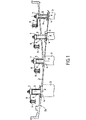
図1は、可変ピッチである複数セットのステータベーン3を支持する外側ケーシング2を有する、ターボ機械の高圧コンプレッサのステータを示す。
FIG. 1 shows a stator of a turbomachine high-pressure compressor having an
ベーン3は、ガス流ストリームにおけるケーシング2の径方向内側に延びる。それらベーンの径方向外側の領域において、各ベーン3は、円形輪郭のプレート4を呈し、このプレート4は、ケーシング2の内側面2aに形成されているキャビティ内に受け入れられ、このプレートは、プレート4の軸線Xのピボット5が上に配置され、ピボット5は、ケーシング2を貫通する円筒状開口部6内に受け入れられる。ピボット5の頭部7は、制御バンド9に結合される制御アーム8を支持している。
The
ベーンの各セットは、それぞれ制御バンド9に結合される。制御バンドを駆動することによって、所定のセットの全てのベーン3を同時に旋回させる。
Each set of vanes is coupled to a control band 9 respectively. By driving the control band, all the
各ピボット5は、円滑な軸受けを形成すべく介挿される少なくとも1つのブッシング10を伴って、開口部6に取り付けられている。
Each
図2は、本発明のブッシング10を示している。ブッシング10は、その外側直径が実質的に開口部6の直径に等しい金属ジャケット11と、ジャケット11の内側壁部11aにろう付けによって固着されるセラミックリング16とを備えている。参照符号12は、セラミックリング16の外側面とジャケット11の内側壁部11aとの間に介挿された、ろう付けの層を表している。
FIG. 2 shows the bushing 10 of the present invention. The
例として、リング16のセラミックは、アルミナから作られている。リング16は、何らかの知られている方法によって作られる。リング16の直径は、ジャケット11の内側直径に実質的に等しく、且つ好ましくはジャケット11の内側直径よりも若干小さい。ろう付け12を構成する材料は、ジャケット11を構成する材料の融点よりも低い融点を有する材料または合金から選択され、本来前記ジャケット材料とセラミックとの両方に濡れる。前記ろう付け材料は、また、コンプレッサが動作中であるとき、または取り付け中にブッシング10がケーシング2に焼きばめされる間に温度が相違する場合に、セラミックが、いかなる引っ張り力または曲げ力にもさらされないように、非常に延性があり且つ冷たいときは収縮し且つ熱いときは膨張する材料から選択される。
As an example, the ceramic of the
ろう付け12の層が、リング16の外側表面全体を覆うので、動作中にあらわれるかもしれないいかなるクラックも、全ての部品がろう付けによって保持されるから、もはや決定的ではなく、そしてリング16の種々の部品が、クラックの場合にジャケット11の適正位置に保持される。リング16は、ろう付けによってジャケット11の内側壁部11aに固着された複数の部品から作られ得る。
Since the layer of brazing 12 covers the entire outer surface of the
ブッシング10は、都合の良いことに、径方向外側向きに延びるカラー13を呈する。カラーの面13aは、プレート4の端面に対する乾燥摩擦を提供すべく、ろう付けによってそれに固定されたセラミックワッシャ14を有する。
The
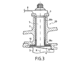
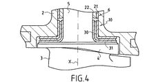
図3および図4は、ピボット5のための円滑な軸受け20の第1の実施形態を示している。
3 and 4 show a first embodiment of a smooth bearing 20 for the
軸受け20は、上述されたようなブッシング10によって構成される底部軸受け20aと、例えばポリイミドからなり、セラミックの摩擦係数よりもかなり低い摩擦係数を有する材料から作られているスリーブ22を取り囲むジャケット21によって構成される頂部軸受け20bとを備える。ブッシング10は、ベーン3上のプレート4に近接して配置され、且つより重く負荷された軸受けに対応している。このブッシングは、相当な量の力を吸収することができ、ピボット5のより重く負荷された端部における摩損を大いに制限するのに役立つ。頂部軸受け20bは、制御アーム8、および制御バンド9を作動させるのに供するアクチュエータの力を制限する。
The
参照符号30は、ピボットがそれ自体、良好な摩擦特性を有する合金によって構成されていない場合に、ピボット5に焼きばめされるニッケル、コバルト、または鉄に基づく挿入リングを示している。この挿入リング30は、都合の良いことに、プレート4の端面にカラー31を含んでいる。
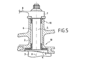
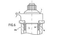
図5から図7は、ピボット5のための円滑な軸受け20の第2の実施形態を示しており、軸受けは、両方とも図2に示されたブッシング10のようなブッシング10から作られた、底部軸受け20aおよび頂部軸受け20bを呈している。
FIGS. 5 to 7 show a second embodiment of a smooth bearing 20 for the
これら2つのブッシングは、より良く力を吸収し、且つ底部軸受け20aおよび頂部軸受け20bの非常に良好な抗摩損作用によって、大いに傾斜を制限する。 These two bushings absorb the force better and greatly limit the tilt due to the very good anti-friction action of the bottom bearing 20a and the top bearing 20b.
2 ケーシング
3 ステータベーン
4 プレート
5 ピボット
6 円筒状開口部
7 頭部
8 制御アーム
9 制御バンド
10 ブッシング
11 金属ジャケット
11a 内側壁部
12 ろう付け層
13 カラー
16 セラミックリング
20 円滑な軸受け
20a 底部軸受け
20b 頂部軸受け
21 ジャケット
22 スリーブ
30 挿入リング
DESCRIPTION OF
Claims (7)
Applications Claiming Priority (2)
| Application Number | Priority Date | Filing Date | Title |
|---|---|---|---|
| FR0403536 | 2004-04-05 | ||
| FR0403536A FR2868490B1 (en) | 2004-04-05 | 2004-04-05 | CERAMIC SOCKET FOR A VARIABLE TURBOMACHINE AUBING TIMING SYSTEM |
Publications (2)
| Publication Number | Publication Date |
|---|---|
| JP2005291212A true JP2005291212A (en) | 2005-10-20 |
| JP4931363B2 JP4931363B2 (en) | 2012-05-16 |
Family
ID=34896711
Family Applications (1)
| Application Number | Title | Priority Date | Filing Date |
|---|---|---|---|
| JP2005107283A Active JP4931363B2 (en) | 2004-04-05 | 2005-04-04 | Ceramic-based bushings for variable pitch vane systems in turbomachinery |
Country Status (8)
| Country | Link |
|---|---|
| US (1) | US7614846B2 (en) |
| EP (1) | EP1584827B1 (en) |
| JP (1) | JP4931363B2 (en) |
| CA (1) | CA2500942C (en) |
| DE (1) | DE602005022647D1 (en) |
| FR (1) | FR2868490B1 (en) |
| RU (1) | RU2405975C2 (en) |
| UA (1) | UA93177C2 (en) |
Cited By (1)
| Publication number | Priority date | Publication date | Assignee | Title |
|---|---|---|---|---|
| WO2023218723A1 (en) * | 2022-05-09 | 2023-11-16 | 三菱重工業株式会社 | Variable stator blade and compressor |
Families Citing this family (12)
| Publication number | Priority date | Publication date | Assignee | Title |
|---|---|---|---|---|
| FR2892147B1 (en) * | 2005-10-18 | 2010-09-17 | Snecma | VARIABLE-TIMING STATOR VANE GUIDING DEVICE IN AXIAL TURBOMACHINE |
| US7445427B2 (en) * | 2005-12-05 | 2008-11-04 | General Electric Company | Variable stator vane assembly and bushing thereof |
| FR2897639B1 (en) * | 2006-02-23 | 2010-08-13 | Snecma | ANTI-WEARING DEVICE FOR A VARIABLE CAMERA ROTATION SYSTEM OF A TURBOMACHINE |
| FR2902822B1 (en) * | 2006-06-21 | 2008-08-22 | Snecma Sa | STATOR BEARING FOR STATOR WITH VARIABLE SHAFT |
| EP1925783B1 (en) * | 2006-11-22 | 2012-05-02 | Siemens Aktiengesellschaft | Variable stator blade assembly |
| FR2913052B1 (en) | 2007-02-22 | 2011-04-01 | Snecma | CONTROL OF AUBES WITH VARIABLE SETTING ANGLE |
| US8596035B2 (en) * | 2011-06-29 | 2013-12-03 | Opra Technologies B.V. | Apparatus and method for reducing air mass flow for extended range low emissions combustion for single shaft gas turbines |
| DE102012212998B4 (en) * | 2012-07-24 | 2023-09-07 | Friedrich Boysen Gmbh & Co. Kg | Bearing system for a shaft |
| US10302011B2 (en) * | 2015-11-23 | 2019-05-28 | Garrett Transportation I Inc. | Exhaust gas variable turbine assembly |
| DE102017222209A1 (en) * | 2017-12-07 | 2019-06-13 | MTU Aero Engines AG | Guide vane connection and turbomachine |
| EP3530764B1 (en) | 2018-02-26 | 2020-08-26 | Roller Bearing Company of America, Inc. | A self lubricating titanium aluminide composite material |
| CN117426042A (en) * | 2021-06-30 | 2024-01-19 | 美国圣戈班性能塑料公司 | Ceramic variable stator vane bushing |
Citations (6)
| Publication number | Priority date | Publication date | Assignee | Title |
|---|---|---|---|---|
| US3764189A (en) * | 1970-12-29 | 1973-10-09 | Mtu Muenchen Gmbh | Bearing for pivotally mounted guide vanes in thermal turbomachines |
| JPS58163820A (en) * | 1982-03-19 | 1983-09-28 | Daido Steel Co Ltd | Slide member |
| JPH06109026A (en) * | 1992-09-24 | 1994-04-19 | Toyota Motor Corp | Bearing structure for high temperature |
| JPH08312373A (en) * | 1995-05-19 | 1996-11-26 | Ishikawajima Harima Heavy Ind Co Ltd | Sliding bearing of variable stator blade for gas turbine |
| US20020154991A1 (en) * | 2001-03-30 | 2002-10-24 | Bowen Wayne Ray | Variable gas turbine compressor vane structure with sintered-and-infiltrated bushing and washer bearings |
| US20040052636A1 (en) * | 2002-09-18 | 2004-03-18 | Schilling Jan Christopher | Methods and apparatus for sealing gas turbine engine variable vane assemblies |
Family Cites Families (5)
| Publication number | Priority date | Publication date | Assignee | Title |
|---|---|---|---|---|
| NL75411C (en) * | 1946-03-20 | |||
| DE3014645C2 (en) * | 1980-04-16 | 1982-12-02 | MTU Motoren- und Turbinen-Union München GmbH, 8000 München | Metal-ceramic component and process for its manufacture |
| US6465110B1 (en) * | 2000-10-10 | 2002-10-15 | Material Sciences Corporation | Metal felt laminate structures |
| FR2850138A1 (en) * | 2003-01-16 | 2004-07-23 | Snecma Moteurs | ANTI-WEAR DEVICE FOR A VARIABLE CALIBRATION SYSTEM OF A TURBOMACHINE BLADE |
| FR2857692B1 (en) * | 2003-07-17 | 2007-05-11 | Snecma Moteurs | SYSTEM FOR GUIDING THE EXTERNAL PIVOT OF A VANE WITH A VARIABLE SETTING ANGLE, TURBOMACHINE STATOR |
-
2004
- 2004-04-05 FR FR0403536A patent/FR2868490B1/en not_active Expired - Fee Related
-
2005
- 2005-03-23 CA CA2500942A patent/CA2500942C/en active Active
- 2005-04-04 DE DE602005022647T patent/DE602005022647D1/en active Active
- 2005-04-04 RU RU2005109761/06A patent/RU2405975C2/en active
- 2005-04-04 JP JP2005107283A patent/JP4931363B2/en active Active
- 2005-04-04 US US11/097,289 patent/US7614846B2/en active Active
- 2005-04-04 EP EP05290734A patent/EP1584827B1/en active Active
- 2005-04-05 UA UAA200503161A patent/UA93177C2/en unknown
Patent Citations (6)
| Publication number | Priority date | Publication date | Assignee | Title |
|---|---|---|---|---|
| US3764189A (en) * | 1970-12-29 | 1973-10-09 | Mtu Muenchen Gmbh | Bearing for pivotally mounted guide vanes in thermal turbomachines |
| JPS58163820A (en) * | 1982-03-19 | 1983-09-28 | Daido Steel Co Ltd | Slide member |
| JPH06109026A (en) * | 1992-09-24 | 1994-04-19 | Toyota Motor Corp | Bearing structure for high temperature |
| JPH08312373A (en) * | 1995-05-19 | 1996-11-26 | Ishikawajima Harima Heavy Ind Co Ltd | Sliding bearing of variable stator blade for gas turbine |
| US20020154991A1 (en) * | 2001-03-30 | 2002-10-24 | Bowen Wayne Ray | Variable gas turbine compressor vane structure with sintered-and-infiltrated bushing and washer bearings |
| US20040052636A1 (en) * | 2002-09-18 | 2004-03-18 | Schilling Jan Christopher | Methods and apparatus for sealing gas turbine engine variable vane assemblies |
Cited By (1)
| Publication number | Priority date | Publication date | Assignee | Title |
|---|---|---|---|---|
| WO2023218723A1 (en) * | 2022-05-09 | 2023-11-16 | 三菱重工業株式会社 | Variable stator blade and compressor |
Also Published As
| Publication number | Publication date |
|---|---|
| US20050220609A1 (en) | 2005-10-06 |
| DE602005022647D1 (en) | 2010-09-16 |
| FR2868490A1 (en) | 2005-10-07 |
| CA2500942C (en) | 2012-10-23 |
| CA2500942A1 (en) | 2005-10-05 |
| FR2868490B1 (en) | 2006-07-28 |
| RU2405975C2 (en) | 2010-12-10 |
| EP1584827B1 (en) | 2010-08-04 |
| JP4931363B2 (en) | 2012-05-16 |
| US7614846B2 (en) | 2009-11-10 |
| UA93177C2 (en) | 2011-01-25 |
| EP1584827A1 (en) | 2005-10-12 |
| RU2005109761A (en) | 2006-10-10 |
Similar Documents
| Publication | Publication Date | Title |
|---|---|---|
| JP4931363B2 (en) | Ceramic-based bushings for variable pitch vane systems in turbomachinery | |
| JP5202837B2 (en) | Variable stator vane assembly | |
| EP1045156B1 (en) | Bushing assembly with removable wear sleeve | |
| US7207770B2 (en) | Variable stator vane bushings and washers | |
| US20070160464A1 (en) | Anti-wear device for a guide pivot of a variable-pitch vane of a turbomachine compressor | |
| CN111630252B (en) | Turbine shroud assembly | |
| US8038387B2 (en) | Bearing for variable pitch stator vane | |
| US9500083B2 (en) | Apparatus and method to reduce wear and friction between CMC-to-metal attachment and interface | |
| EP0179539B1 (en) | Turbine rotor units and method of producing the same | |
| US20040086380A1 (en) | Face seal assembly with composite stator | |
| US7094022B2 (en) | Variable stator vane bushings and washers | |
| EP2942530B1 (en) | Turbomachine | |
| JP2006105129A (en) | Shroud segment for turbine engine | |
| US20050008489A1 (en) | Antiwear device for a variable pitch system for a turbomachine vane | |
| JP2005171986A (en) | Method for improving wear characteristics of bushing and wear-resistant bushing | |
| EP1772598A2 (en) | Exhaust valve bushing | |
| JP4667137B2 (en) | Drain tube for low pressure shaft of turbomachine | |
| KR100860180B1 (en) | Exhaust valve bushing | |
| CN101638994A (en) | Turbomachine component damping structure and method of damping vibration of a turbomachine component | |
| WO2012170188A2 (en) | Exhaust-gas turbocharger | |
| JP2011226469A (en) | Turbocharger | |
| JP4475430B2 (en) | Method for adapting turbo engine and stator and rotor of turbo engine | |
| JP2006266466A (en) | Method for improving abrasion characteristics of bushing and wear-resistant bushing | |
| JP5828392B2 (en) | Roll for hot metal plating bath | |
| WO2017126543A1 (en) | Shroud structural body and turbocharger |
Legal Events
| Date | Code | Title | Description |
|---|---|---|---|
| A621 | Written request for application examination |
Free format text: JAPANESE INTERMEDIATE CODE: A621 Effective date: 20080229 |
|
| A131 | Notification of reasons for refusal |
Free format text: JAPANESE INTERMEDIATE CODE: A131 Effective date: 20101026 |
|
| A601 | Written request for extension of time |
Free format text: JAPANESE INTERMEDIATE CODE: A601 Effective date: 20110120 |
|
| A602 | Written permission of extension of time |
Free format text: JAPANESE INTERMEDIATE CODE: A602 Effective date: 20110125 |
|
| A521 | Request for written amendment filed |
Free format text: JAPANESE INTERMEDIATE CODE: A523 Effective date: 20110419 |
|
| A131 | Notification of reasons for refusal |
Free format text: JAPANESE INTERMEDIATE CODE: A131 Effective date: 20110607 |
|
| A601 | Written request for extension of time |
Free format text: JAPANESE INTERMEDIATE CODE: A601 Effective date: 20110905 |
|
| A602 | Written permission of extension of time |
Free format text: JAPANESE INTERMEDIATE CODE: A602 Effective date: 20110908 |
|
| A521 | Request for written amendment filed |
Free format text: JAPANESE INTERMEDIATE CODE: A523 Effective date: 20111201 |
|
| TRDD | Decision of grant or rejection written | ||
| A01 | Written decision to grant a patent or to grant a registration (utility model) |
Free format text: JAPANESE INTERMEDIATE CODE: A01 Effective date: 20120207 |
|
| A01 | Written decision to grant a patent or to grant a registration (utility model) |
Free format text: JAPANESE INTERMEDIATE CODE: A01 |
|
| A61 | First payment of annual fees (during grant procedure) |
Free format text: JAPANESE INTERMEDIATE CODE: A61 Effective date: 20120214 |
|
| R150 | Certificate of patent or registration of utility model |
Ref document number: 4931363 Country of ref document: JP Free format text: JAPANESE INTERMEDIATE CODE: R150 Free format text: JAPANESE INTERMEDIATE CODE: R150 |
|
| FPAY | Renewal fee payment (event date is renewal date of database) |
Free format text: PAYMENT UNTIL: 20150224 Year of fee payment: 3 |
|
| R250 | Receipt of annual fees |
Free format text: JAPANESE INTERMEDIATE CODE: R250 |
|
| R250 | Receipt of annual fees |
Free format text: JAPANESE INTERMEDIATE CODE: R250 |
|
| R250 | Receipt of annual fees |
Free format text: JAPANESE INTERMEDIATE CODE: R250 |
|
| R250 | Receipt of annual fees |
Free format text: JAPANESE INTERMEDIATE CODE: R250 |
|
| R250 | Receipt of annual fees |
Free format text: JAPANESE INTERMEDIATE CODE: R250 |
|
| R250 | Receipt of annual fees |
Free format text: JAPANESE INTERMEDIATE CODE: R250 |
|
| R250 | Receipt of annual fees |
Free format text: JAPANESE INTERMEDIATE CODE: R250 |
|
| R250 | Receipt of annual fees |
Free format text: JAPANESE INTERMEDIATE CODE: R250 |
|
| R250 | Receipt of annual fees |
Free format text: JAPANESE INTERMEDIATE CODE: R250 |
|
| R250 | Receipt of annual fees |
Free format text: JAPANESE INTERMEDIATE CODE: R250 |