JP2005291204A - Turbine casing having heat-resistant hooks and obtained by powder metallurgy - Google Patents
Turbine casing having heat-resistant hooks and obtained by powder metallurgy Download PDFInfo
- Publication number
- JP2005291204A JP2005291204A JP2005087761A JP2005087761A JP2005291204A JP 2005291204 A JP2005291204 A JP 2005291204A JP 2005087761 A JP2005087761 A JP 2005087761A JP 2005087761 A JP2005087761 A JP 2005087761A JP 2005291204 A JP2005291204 A JP 2005291204A
- Authority
- JP
- Japan
- Prior art keywords
- jacket
- hooks
- alloy
- stator casing
- turbine stator
- Prior art date
- Legal status (The legal status is an assumption and is not a legal conclusion. Google has not performed a legal analysis and makes no representation as to the accuracy of the status listed.)
- Granted
Links
Images
Classifications
-
- B—PERFORMING OPERATIONS; TRANSPORTING
- B22—CASTING; POWDER METALLURGY
- B22F—WORKING METALLIC POWDER; MANUFACTURE OF ARTICLES FROM METALLIC POWDER; MAKING METALLIC POWDER; APPARATUS OR DEVICES SPECIALLY ADAPTED FOR METALLIC POWDER
- B22F7/00—Manufacture of composite layers, workpieces, or articles, comprising metallic powder, by sintering the powder, with or without compacting wherein at least one part is obtained by sintering or compression
- B22F7/06—Manufacture of composite layers, workpieces, or articles, comprising metallic powder, by sintering the powder, with or without compacting wherein at least one part is obtained by sintering or compression of composite workpieces or articles from parts, e.g. to form tipped tools
- B22F7/062—Manufacture of composite layers, workpieces, or articles, comprising metallic powder, by sintering the powder, with or without compacting wherein at least one part is obtained by sintering or compression of composite workpieces or articles from parts, e.g. to form tipped tools involving the connection or repairing of preformed parts
-
- B—PERFORMING OPERATIONS; TRANSPORTING
- B22—CASTING; POWDER METALLURGY
- B22F—WORKING METALLIC POWDER; MANUFACTURE OF ARTICLES FROM METALLIC POWDER; MAKING METALLIC POWDER; APPARATUS OR DEVICES SPECIALLY ADAPTED FOR METALLIC POWDER
- B22F3/00—Manufacture of workpieces or articles from metallic powder characterised by the manner of compacting or sintering; Apparatus specially adapted therefor ; Presses and furnaces
- B22F3/12—Both compacting and sintering
- B22F3/14—Both compacting and sintering simultaneously
- B22F3/15—Hot isostatic pressing
-
- B—PERFORMING OPERATIONS; TRANSPORTING
- B22—CASTING; POWDER METALLURGY
- B22F—WORKING METALLIC POWDER; MANUFACTURE OF ARTICLES FROM METALLIC POWDER; MAKING METALLIC POWDER; APPARATUS OR DEVICES SPECIALLY ADAPTED FOR METALLIC POWDER
- B22F7/00—Manufacture of composite layers, workpieces, or articles, comprising metallic powder, by sintering the powder, with or without compacting wherein at least one part is obtained by sintering or compression
- B22F7/06—Manufacture of composite layers, workpieces, or articles, comprising metallic powder, by sintering the powder, with or without compacting wherein at least one part is obtained by sintering or compression of composite workpieces or articles from parts, e.g. to form tipped tools
- B22F7/08—Manufacture of composite layers, workpieces, or articles, comprising metallic powder, by sintering the powder, with or without compacting wherein at least one part is obtained by sintering or compression of composite workpieces or articles from parts, e.g. to form tipped tools with one or more parts not made from powder
-
- F—MECHANICAL ENGINEERING; LIGHTING; HEATING; WEAPONS; BLASTING
- F01—MACHINES OR ENGINES IN GENERAL; ENGINE PLANTS IN GENERAL; STEAM ENGINES
- F01D—NON-POSITIVE DISPLACEMENT MACHINES OR ENGINES, e.g. STEAM TURBINES
- F01D25/00—Component parts, details, or accessories, not provided for in, or of interest apart from, other groups
- F01D25/24—Casings; Casing parts, e.g. diaphragms, casing fastenings
- F01D25/246—Fastening of diaphragms or stator-rings
-
- F—MECHANICAL ENGINEERING; LIGHTING; HEATING; WEAPONS; BLASTING
- F01—MACHINES OR ENGINES IN GENERAL; ENGINE PLANTS IN GENERAL; STEAM ENGINES
- F01D—NON-POSITIVE DISPLACEMENT MACHINES OR ENGINES, e.g. STEAM TURBINES
- F01D9/00—Stators
- F01D9/02—Nozzles; Nozzle boxes; Stator blades; Guide conduits, e.g. individual nozzles
- F01D9/04—Nozzles; Nozzle boxes; Stator blades; Guide conduits, e.g. individual nozzles forming ring or sector
-
- Y—GENERAL TAGGING OF NEW TECHNOLOGICAL DEVELOPMENTS; GENERAL TAGGING OF CROSS-SECTIONAL TECHNOLOGIES SPANNING OVER SEVERAL SECTIONS OF THE IPC; TECHNICAL SUBJECTS COVERED BY FORMER USPC CROSS-REFERENCE ART COLLECTIONS [XRACs] AND DIGESTS
- Y10—TECHNICAL SUBJECTS COVERED BY FORMER USPC
- Y10T—TECHNICAL SUBJECTS COVERED BY FORMER US CLASSIFICATION
- Y10T29/00—Metal working
- Y10T29/49—Method of mechanical manufacture
- Y10T29/49316—Impeller making
- Y10T29/4932—Turbomachine making
Landscapes
- Engineering & Computer Science (AREA)
- Mechanical Engineering (AREA)
- General Engineering & Computer Science (AREA)
- Manufacturing & Machinery (AREA)
- Chemical & Material Sciences (AREA)
- Composite Materials (AREA)
- Materials Engineering (AREA)
- Powder Metallurgy (AREA)
- Pressure Welding/Diffusion-Bonding (AREA)
Abstract
【課題】ファスナフックが、良好な機械的強度を呈しかつ加熱によく耐える簡単な構造の組み立て手段によって前記ジャケットに固定される、改善されたタービンステータケーシングを提供する。
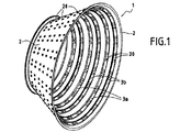
【解決手段】ジャケットと、タービンディストリビュータノズルを締め付けるためのファスナフック3a、3bとを備え、フックは、ジャケットの内側面から突出している、タービンステータケーシングであって、ジャケットは、金属粉末5を用いる熱間等方圧圧縮によって第1の合金で作られ、ファスナフック3a、3bは、第1の合金よりも耐熱性のある第2の合金から作られ、かつ熱間等方圧圧縮の間に拡散溶接によってジャケットに固着される。ケーシングは、また、ファスナフック3a、3bを通過しかつジャケットを通るインサート20を備えている。
【選択図】 図1An improved turbine stator casing is provided in which fastener hooks are secured to the jacket by means of a simple construction that exhibits good mechanical strength and withstands heating.
A turbine stator casing includes a jacket and fastener hooks (3a, 3b) for tightening a turbine distributor nozzle, the hook projecting from an inner surface of the jacket, and the jacket uses a metal powder (5). Made of a first alloy by hot isostatic pressing, fastener hooks 3a, 3b are made of a second alloy that is more heat resistant than the first alloy and during hot isostatic pressing. Fixed to the jacket by diffusion welding. The casing also includes an insert 20 that passes through the fastener hooks 3a, 3b and through the jacket.
[Selection] Figure 1
Description
本発明は、タービンステータケーシングと、それを製造する方法に関する。より詳細には、本発明は、航空機ターボジェットにおけるタービンのためのステータケーシングに関する。 The present invention relates to a turbine stator casing and a method for manufacturing the same. More particularly, the present invention relates to a stator casing for a turbine in an aircraft turbojet.
このようなケーシングは、概してフラストコニカル(frustoconical)形状のジャケットと、前記ジャケットに固定されかつその内側面から突出するファスナフックとを備えている。ファスナフックは、ステータブレードを支持しているリングまたはリングセグメントを支持するために使用され、それらはともに、一般にタービンのディストリビュータノズルと称されるアセンブリを形成している。ステータは、概して、複数のノズルを支持するためにジャケットの内側面に配分される、複数の一連のフックを備えている。これらのリングの間に、タービンロータの可動ブレードを支持するロータホイールが設置されている。ノズルとロータホイールによって構成される一対は、タービンの一つの段を構成する。 Such a casing comprises a jacket that is generally frustoconical in shape and a fastener hook that is fixed to the jacket and protrudes from its inner surface. Fastener hooks are used to support the rings or ring segments that support the stator blades, which together form an assembly commonly referred to as a turbine distributor nozzle. The stator generally includes a plurality of series of hooks that are distributed on the inner surface of the jacket to support the plurality of nozzles. A rotor wheel that supports the movable blades of the turbine rotor is installed between these rings. A pair constituted by the nozzle and the rotor wheel constitutes one stage of the turbine.
航空機ターボジェットのタービンは、非常に高温でタービンを通過する燃焼ガスを有し、したがって特に困難な温度条件のもとで動作する。それゆえ、燃焼ガス流と接触するファスナフックは、より大きな加熱を受け、ジャケットは、いずれにせよ、その外側面において、概して、このジャケットに冷却空気を吹き付ける穿孔されたパイプのシステムである、一般に「シャワーカラー」と称される冷却システムによって冷却される。 Aircraft turbojet turbines have combustion gases that pass through the turbine at very high temperatures and therefore operate under particularly difficult temperature conditions. Therefore, the fastener hooks in contact with the combustion gas stream are subjected to greater heating, and the jacket is in any case, on its outer surface, generally a perforated pipe system that blows cooling air onto the jacket. It is cooled by a cooling system called “shower collar”.
欧州特許出願公開第1288444号に示されるように、合金でそのようなファスナフックを作ることが知られており、合金は、高温によく耐え、かつジャケットの内側において前記フックの位置に応じて場合によっては異なってよい。より一般的な合金、フックの合金よりも耐熱性が低く、かつそれゆえ形成するのがより容易でかつより安価である合金で、ジャケットを作ることも知られている。 It is known to make such fastener hooks with an alloy, as shown in EP 1 288 444, which can withstand high temperatures and depending on the position of the hook inside the jacket. It may be different. It is also known to make jackets with a more common alloy, an alloy that has a lower heat resistance than a hook alloy and is therefore easier and cheaper to form.
この知られている実施形態において、フックは、締まりばめによって、従来の溶接によって、またはボルト締めによって、ジャケットに固定される。それら種々の組み立て方法も、やはり欠点をもたらす。 In this known embodiment, the hook is secured to the jacket by an interference fit, by conventional welding, or by bolting. These various assembly methods also have drawbacks.
例えば、溶融による従来の溶接は、溶融領域における高温割れ、および溶接の間に熱的に影響を受けた領域における割れの発生を助長する。ボルト締めは、ケーシングの構造を複雑にし、かつケーシングを作る部品の数を増大させる。そして、それらの組み立て手段には、疲労に対して一般的に満足すべき抵抗を示すものはない。
本発明は、ジャケットが、特別な製造の方法を用いて作られ、ファスナフックが、良好な機械的強度を呈しかつ加熱によく耐える簡単な構造の組み立て手段によって前記ジャケットに固定される、改善されたタービンステータケーシングに関する。 The invention is improved in that the jacket is made using a special manufacturing method and the fastener hooks are fixed to the jacket by means of a simple construction that exhibits good mechanical strength and well withstands heating. The present invention relates to a turbine stator casing.
その最も一般的な形態においては、本発明は、ジャケットと、タービンディストリビュータノズルを締め付けるためのファスナフックとを備え、フックは、ジャケットの内側面から突出している、タービンステータケーシングであって、前記ジャケットは、金属粉末を用いる熱間等方圧圧縮によって第1の合金で作られ、前記ファスナフックは、第1の合金よりも耐熱性のある第2の合金で作られ、かつ熱間等方圧圧縮の間に拡散溶接によって前記ジャケットに固着されることを特徴とするケーシングを提供する。 In its most general form, the invention comprises a turbine stator casing comprising a jacket and a fastener hook for tightening a turbine distributor nozzle, the hook projecting from an inner surface of the jacket, wherein the jacket Is made of a first alloy by hot isostatic pressing using metal powder, and the fastener hook is made of a second alloy that is more heat resistant than the first alloy and is hot isostatically pressed. A casing is provided that is secured to the jacket by diffusion welding during compression.
熱間等方圧圧縮(Hot Isostatic Compression)(ここでは「HIC」と称される)によってケーシングジャケットを作るという事実が、以下においてより詳細に説明されているように、知られている製造技術の利点による恩恵を受けることを可能とさせることが、最初に分かる。 The fact that the casing jacket is made by hot isostatic compression (referred to herein as “HIC”), as explained in more detail below, It is first seen that it is possible to benefit from the benefits.
本発明の他の利点は、拡散溶接によってファスナフックをジャケットに固定するために、HICを実施するためのサイクルの利点が採用され、それゆえケーシングの製造の間の時間を節約するという事実にある。拡散溶接技術は、それらが異なる組成を有する合金からなっているが、それにもかかわらず拡散の観点から相容性があるときに、2つの部品がともに組み立てられることを可能とする知られている技術である。 Another advantage of the present invention resides in the fact that the advantage of a cycle for performing HIC is employed to secure the fastener hook to the jacket by diffusion welding, thus saving time during the manufacture of the casing. . Diffusion welding techniques are known that allow two parts to be assembled together when they are made of alloys having different compositions but are nevertheless compatible from a diffusion point of view Technology.
したがって、本発明においては、フックは、例えば、少なくとも900℃の温度に耐えることができるように、第1の合金よりも耐熱性のある第2の合金で作られているのに対して、ジャケットは、約750℃までの温度にのみ耐えることができる。当然、ジャケットの内側のフックの位置、およびそれらが受けるであろう温度に応じて、より大きなまたはより小さな範囲の耐熱性を有する、異なるタイプの第2の合金を使用することが可能である。あるタイプのターボジェットについて、タービンのいくつかの段階における温度が、1050℃にあるいは1100℃にまでも達し得ることが知られている。 Thus, in the present invention, the hook is made of a second alloy that is more heat resistant than the first alloy so that it can withstand, for example, a temperature of at least 900 ° C., whereas the jacket is Can only withstand temperatures up to about 750 ° C. Of course, it is possible to use different types of second alloys that have a greater or lesser range of heat resistance, depending on the location of the hooks inside the jacket and the temperature they will experience. For certain types of turbojets, it is known that temperatures at several stages of the turbine can reach 1050 ° C or even 1100 ° C.
都合の良いことに、フックは、ニッケルおよび/またはコバルトを含有する鋳造合金で作られており、等軸単結晶(equiaxial monocrystalline)の鋳造法によって、あるいは方向付けされた凝固(directed solidification)による鋳造によって作られることもできる。一般的に、タービンブレードを作るために使用される合金に類似した合金のフックを作ることが決定され得る。 Conveniently, the hooks are made of a cast alloy containing nickel and / or cobalt and are cast by an equiaxed monocrystalline casting method or by directed solidification. Can also be made. In general, it can be determined to make an alloy hook similar to the alloy used to make the turbine blade.
ジャケットは、商標Waspaloy(登録商標)のもとで販売される合金、または商標Inconel 718(登録商標)のもとで知られる合金のような、航空機に通常使用される合金または超合金で作られる。このことは、損傷をこうむった後に、溶接、アセンブリ、または再充填(re−filling)などの従来の修繕技術を用いて、そのようなジャケットを修繕するのを容易にする。例えば、製造または取り扱いの間の衝撃の結果として、ジャケットに対する損傷が生じるかもしれない。 The jacket is made of an alloy or superalloy commonly used in aircraft, such as an alloy sold under the trademark Waspaloy® or an alloy known under the trademark Inconel 718® . This makes it easier to repair such jackets using conventional repair techniques such as welding, assembly, or re-filling after they have been damaged. For example, damage to the jacket may occur as a result of impact during manufacturing or handling.
要約すれば、ジャケットおよびフックについての使用における要求が異なっているから、異なる第1および第2の合金を使用することは有利である。フックは、非常に高い温度に耐えるために、上述の全てにおいて、良好な能力を呈していなければならないのに対して、ジャケットは、そのような良好な抵抗を呈する必要はないが、容易に修繕できなければならない。さらにまた、フックは、高い温度によく耐えるから、冷却空気でそれらフックを冷却する必要はない。 In summary, it is advantageous to use different first and second alloys because the requirements in use for jackets and hooks are different. Hooks must exhibit good performance in all of the above to withstand very high temperatures, whereas jackets do not have to exhibit such good resistance, but are easily repaired. It must be possible. Furthermore, since the hooks withstand high temperatures well, there is no need to cool them with cooling air.
本発明の特別な実施形態においては、ケーシングは、ファスナフックおよび前記ジャケットを通過するインサートを含んでいる。都合の良いことに、インサートも、熱間等方圧圧縮の間に拡散溶接によって前記ジャケットに固定される。 In a special embodiment of the invention, the casing includes a fastener hook and an insert that passes through the jacket. Conveniently, the insert is also secured to the jacket by diffusion welding during hot isostatic pressing.
たとえ、それらが、ケーシングの構造を若干複雑にしたとしても、このようなインサートは、いくつかの利点をもたらす。最初に、それらインサートは、HICサイクルの間にフックが適切に配置されることを保証するように、ケーシングの製造の間に、フックをジャケットが形成される鋳型の一部に固定することを可能とする。その後は、インサートは、突出部を形成するように、ジャケットの外側面から突出することができる。これらの突出部は、次に要素、例えば冷却システムの要素を、ケーシングの外側に固定するために有用であり得る。各インサートに、突出部に開口するねじ山が切られた孔を設け、かつその孔に、ケーシングの外側の要素に固着されたネジが形成されたシャンクを、ネジ留めすることさえも可能である。 Such inserts offer several advantages, even if they make the casing construction somewhat complicated. Initially, the inserts can secure the hook to the part of the mold from which the jacket is formed during the manufacture of the casing to ensure that the hook is properly positioned during the HIC cycle. And Thereafter, the insert can protrude from the outer surface of the jacket to form a protrusion. These protrusions can then be useful for securing elements, such as elements of the cooling system, to the outside of the casing. Each insert can be provided with a threaded hole that opens into the projection, and the hole can even be screwed with a threaded shank secured to an element outside the casing. .
本発明は、第1の合金で作られたジャケットと、タービンディストリビュータノズルを締め付けるためのファスナフックとを備え、フックは、前記ジャケットの内側面から突出している、タービンステータケーシングを製造する方法であって、前記フックは、第1の合金よりも耐熱性のある第2の合金で作られ、フックは、鋳型の内部に配置され、鋳型は、第1の合金の金属粉末が充填されるとともに、フックは、前記粉末に接触するような態様で配置され、そして前記ジャケットが、前記金属粉末の熱間等方圧圧縮によって成形され、フックは、熱間等方圧圧縮の間に拡散溶接によってジャケットに固着されることを特徴とする方法をさらに提供する。 The present invention is a method of manufacturing a turbine stator casing comprising a jacket made of a first alloy and a fastener hook for tightening a turbine distributor nozzle, the hook protruding from the inner surface of the jacket. The hook is made of a second alloy that is more heat resistant than the first alloy, the hook is placed inside the mold, the mold is filled with the metal powder of the first alloy, The hook is arranged in contact with the powder, and the jacket is formed by hot isostatic pressing of the metal powder, and the hook is jacketed by diffusion welding during hot isostatic pressing. Further provided is a method characterized in that the method is fixed to the surface.
本発明のケーシングおよびケーシングを製造する方法の利点は、以下における本発明の特定の実施形態の詳細な説明を読めば、よりよく理解されるであろう。 The advantages of the casing and the method of manufacturing the casing of the present invention will be better understood after reading the following detailed description of specific embodiments of the present invention.
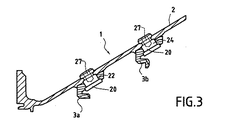
図1、図3、および図4を参照すると、図示されたケーシング1の例は、ジャケット2に固定された2つのタイプのフック、すなわちフラットフック3aおよびリップフック3bを有する、概してフラストコニカル形状のジャケット2を備えている。同一のタイプのフックは、湾曲されたセグメントの形状をなし、かつそれらフックは、ジャケット2の内側面にフックのリングを形成するように、端と端とをつなげて配置されている。
Referring to FIGS. 1, 3 and 4, the illustrated casing 1 example has two types of hooks secured to a
図1に示された例においては、ケーシング1は、フラットフック3aの3つのリングおよびリップフック3bの3つのリングを有しており、これら異なるタイプのリングは、交互配置されている。
In the example shown in FIG. 1, the casing 1 has three rings of
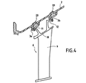
図4に示されるように、フック3aおよび3bは、ステータブレード9を支持するリングまたはリングセグメントから構成されるタービンディストリビュータノズル6を支持するのに役立っている。これらのステータブレード9は、それらの根元部(root)を介して、ノズル6の外側リング10に結合されている。外側リング10は、その前側および後側に、外側リング10がファスナフック3aおよび3bによって保持されるように、それぞれジャケット2のファスナフック3aおよび3bと協働するのに適するフック11およびフック12が設けられている。
As shown in FIG. 4, the
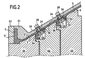
ケーシング1の構造が十分に理解され、次に、図2を参照して与えられる、ケーシングを製造する方法の説明に移る。この図は、熱間等方圧圧縮、すなわち圧力の印加に関連する特定の加熱サイクルに供されるために、第1の合金の金属粉末5がその中に注入される鋳型を作るために使用される金型(tooling)を示している。
Now that the structure of the casing 1 is fully understood, we will now turn to the description of the method for manufacturing the casing, given with reference to FIG. This figure is used to make a mold into which a
実際には、鋳型は、複数の内側金型部品O1、O2、O3、および外側金型部品E1およびE2から作られる。 In practice, the mold is made from a plurality of inner mold parts O1, O2, O3 and outer mold parts E1 and E2.
これらの金型部品の設計は、高度に精密であり、特に、ジャケット2が形成されるHICの間における局所収縮のモデルを含む、コンピュータ支援設計(CAD)を使用する。この特別な技術は、Isoprec(登録商標)方法の名前のもとに知られており、直接的な設計寸法で、ケーシングジャケットを得ることを可能にし、それによって後続の機械加工の必要性を低減する。
The design of these mold parts is highly precise, and in particular uses computer aided design (CAD), which includes a model of local shrinkage between the HICs in which the
図2に示されるように、実質的に円筒状のインサート20は、HICの間に適正な位置にフック3aまたは3bを保持するために使用される。説明された例においては、円環状に対称であるそのようなインサート20は、フック3aまたは3bに形成された円形開口部23を通過するための円筒状本体24を備え、かつ第1の端部に、フック3aまたは3bに対する当接部となるように、開口部23の直径よりも大きい直径を有する円環状肩部22を備えている。例においては、本体24の直径は、開口23のそれよりも非常にわずかに小さく、インサートとフック3aまたは3bとの間の間隔が、フックの係合が外れることなく、かつインサート20の固定位置に残ることを確実にするためにさらに小さい。開口部23に圧入として取り付けられるべくインサート20を設けることも可能である。
As shown in FIG. 2, a substantially
第1の端部から遠く、従って外側を向いたインサート20の第2の端部は、外側金型E1にこの目的のために設けられたハウジング29に受け入れられるのに適している。孔は、この金型E1を貫通し、一端においてその外側表面に、かつその他端においてハウジング29内に開口している。ねじ山が切られた他の孔27は、インサート20内に形成され、その第2の端部において開口している。これらの孔27および29は、ネジ28が貫通するのを可能にする。ネジ28が、ねじ切りされた孔27内に締め付けられたとき、インサート20の第2の端部は、ハウジング29の端部に対して当接し、フック3aまたは3bが固定位置に保持される。この位置は、フックの外側面30が、内側金型O1、O2、およびO3の外側面Sと揃うような位置である。したがって外側面Sは、外側金型E1およびE2の内側面S’およびフック3aおよび3bの外側面30と協働し、金属粉末5が内部に注入される鋳型の壁部を形成する。それゆえ、フック3aおよび3bの外側面30は、HICによって圧縮されるときに粉末5と接触する。
The second end of the
実際のHICを行うために、金型、フック、インサート、ネジ、および粉末によって構成されるアセンブリは、高圧および高温、例えば1000バールの圧力および温度1200℃のオートクレーブ内に配置される。アセンブリは、それから、温度および圧力の作用のもとで圧縮され、そして金属粉末は、ジャケット2を形成するために高密度化される。さらに、ジャケット2ならびにフック3aおよび3bは、それらがともに拡散溶接によって溶接されることを可能とするように、相容性の組成を有する合金から作られるように選択される。従来のやり方においては、拡散溶接は、制御された時間の長さについて所定の圧力および温度のもとで、部品、この場合においては、ジャケット2ならびにフック3aおよび3bを、接触状態に維持する方法である。この場合において、適切な温度および圧力条件が、HICサイクルの間に到達される。部品の表面において作られる塑性変形は、接触が密であることを確実にし、かつ要素が、相容性のある合金からなるなら、部品間において移動するすなわち拡散することを確実にする。
To perform the actual HIC, the assembly composed of molds, hooks, inserts, screws and powder is placed in an autoclave at high pressure and high temperature, for example at a pressure of 1000 bar and a temperature of 1200 ° C. The assembly is then compressed under the action of temperature and pressure, and the metal powder is densified to form the
拡散溶接方法は、フック3aおよび3bの外側面30が適切に調整されることが必要であることが、観察されるはずである。
It should be observed that the diffusion welding method requires that the outer surfaces 30 of
都合の良いことに、第1の合金よりもより耐熱性があり、かつ拡散の観点から第1の合金と相容性がある、第2の合金と同一または類似している第3の合金で作られるインサート20が使用される。
Conveniently, a third alloy that is more heat resistant than the first alloy and compatible with the first alloy from a diffusion point of view is the same or similar to the second alloy. The
したがって、フック3aおよび3bと同様に、インサート20は、HICサイクルの間に拡散溶接によってジャケット2に接合される。
Thus, like the
図示される例においては、本体24およびインサート20にも周囲溝26が存在する。この溝26は、環状であり、本体24が金属粉末5と接触する領域に形成される。それゆえ、粉末5は、製造の間にジャケット2の主要部の中に埋設される溝26の内側に浸透する。任意の溝26は、それゆえ、インサート20とジャケット2との間の締め付けを改善する。
In the illustrated example, the
一旦ジャケット2が成形されると、例えば軟鋼からなる鋳型については、酸、例えば硝酸の中で溶解されることによって、鋳型は破壊され、その後にネジ28はゆるめられる。
Once the
その後、ケーシングは、航空機ターボジェットの内側に取り付けられる。自由なねじが切られた孔27は、次に対応するネジ付きタンクに嵌合され、それゆえ冷却するためにケーシング1に冷気が吹き付けられることを可能とする、穿孔されたパイプを締め付けるために使用され得る。
The casing is then attached to the inside of the aircraft turbojet. The free threaded
1 ケーシング
2 ジャケット
3a、3b フック
5 金属粉末
6 ディストリビュータノズル
9 ステータブレード
10 外側リング
11、12 フック
20 インサート
23 開口部
24 円筒状本体
26 周囲溝
27 孔
28 ネジ
29 ハウジング
30 フック外側面
O1、O2、O3、E1、E2 金型部品
DESCRIPTION OF SYMBOLS 1
Claims (12)
Applications Claiming Priority (1)
| Application Number | Priority Date | Filing Date | Title |
|---|---|---|---|
| FR0403537A FR2868467B1 (en) | 2004-04-05 | 2004-04-05 | TURBINE HOUSING WITH REFRACTORY HOOKS OBTAINED BY CDM PROCESS |
Publications (2)
| Publication Number | Publication Date |
|---|---|
| JP2005291204A true JP2005291204A (en) | 2005-10-20 |
| JP4153501B2 JP4153501B2 (en) | 2008-09-24 |
Family
ID=34531413
Family Applications (1)
| Application Number | Title | Priority Date | Filing Date |
|---|---|---|---|
| JP2005087761A Expired - Lifetime JP4153501B2 (en) | 2004-04-05 | 2005-03-25 | Turbine casing having heat-resistant hooks and obtained by powder metallurgy |
Country Status (6)
| Country | Link |
|---|---|
| US (1) | US7234920B2 (en) |
| JP (1) | JP4153501B2 (en) |
| CA (1) | CA2500959C (en) |
| FR (1) | FR2868467B1 (en) |
| GB (1) | GB2412949B (en) |
| RU (1) | RU2372496C2 (en) |
Cited By (1)
| Publication number | Priority date | Publication date | Assignee | Title |
|---|---|---|---|---|
| JP2014001451A (en) * | 2012-05-30 | 2014-01-09 | Rolls Royce Plc | Apparatus and method of manufacturing article from powder material |
Families Citing this family (27)
| Publication number | Priority date | Publication date | Assignee | Title |
|---|---|---|---|---|
| DE10359730A1 (en) * | 2003-12-19 | 2005-07-14 | Mtu Aero Engines Gmbh | Turbomachine, in particular gas turbine |
| FR2871398B1 (en) * | 2004-06-15 | 2006-09-29 | Snecma Moteurs Sa | METHOD FOR MANUFACTURING A TURBINE STATOR CASTER |
| US20060096091A1 (en) | 2004-10-28 | 2006-05-11 | Carrier Charles W | Method for manufacturing aircraft engine cases with bosses |
| GB2442238B (en) * | 2006-09-29 | 2008-10-01 | Rolls Royce Plc | Sheet metal blank |
| EP2159382A1 (en) * | 2008-08-27 | 2010-03-03 | Siemens Aktiengesellschaft | Lead rotor holder for a gas turbine |
| EP2196628A1 (en) * | 2008-12-10 | 2010-06-16 | Siemens Aktiengesellschaft | Lead rotor holder |
| FR2944724B1 (en) * | 2009-04-24 | 2012-01-20 | Snecma | METHOD FOR MANUFACTURING AN ASSEMBLY COMPRISING A PLURALITY OF AUBES MOUNTED IN A PLATFORM |
| US8392016B2 (en) | 2010-06-25 | 2013-03-05 | LNT PM Inc. | Adaptive method for manufacturing of complicated shape parts by hot isostatic pressing of powder materials with using irreversibly deformable capsules and inserts |
| US9079245B2 (en) | 2011-08-31 | 2015-07-14 | Pratt & Whitney Canada Corp. | Turbine shroud segment with inter-segment overlap |
| US8784044B2 (en) | 2011-08-31 | 2014-07-22 | Pratt & Whitney Canada Corp. | Turbine shroud segment |
| US9028744B2 (en) | 2011-08-31 | 2015-05-12 | Pratt & Whitney Canada Corp. | Manufacturing of turbine shroud segment with internal cooling passages |
| US8784037B2 (en) | 2011-08-31 | 2014-07-22 | Pratt & Whitney Canada Corp. | Turbine shroud segment with integrated impingement plate |
| US8784041B2 (en) | 2011-08-31 | 2014-07-22 | Pratt & Whitney Canada Corp. | Turbine shroud segment with integrated seal |
| GB201119238D0 (en) | 2011-11-08 | 2011-12-21 | Rolls Royce Plc | A hot isostatic pressing tool and a method of manufacturing an article from powder material by hot isostatic pressing |
| GB201119240D0 (en) | 2011-11-08 | 2011-12-21 | Rolls Royce Plc | A hot isostatic pressing tool and a method of manufacturing an article from powder material by hot isostatic pressing |
| GB2510562B (en) | 2013-02-06 | 2015-02-25 | Rolls Royce Plc | Method of forming a bonded assembly |
| FR3002272A1 (en) * | 2013-02-19 | 2014-08-22 | Snecma | ANTI-ROTATION DISTRIBUTOR SECTOR FOR ADJACENT AREA |
| US10252371B2 (en) * | 2016-02-12 | 2019-04-09 | The Boeing Company | Diffusion-bonded metallic materials |
| GB201700614D0 (en) * | 2017-01-13 | 2017-03-01 | Rolls Royce Plc | A method of manufacturing a component |
| FR3071516B1 (en) * | 2017-09-25 | 2022-07-29 | Safran Aircraft Engines | METHOD FOR MANUFACTURING A PART COMPRISING TWO DIFFERENT SUPERALLOYS |
| US10533454B2 (en) | 2017-12-13 | 2020-01-14 | Pratt & Whitney Canada Corp. | Turbine shroud cooling |
| US11274569B2 (en) | 2017-12-13 | 2022-03-15 | Pratt & Whitney Canada Corp. | Turbine shroud cooling |
| US10502093B2 (en) * | 2017-12-13 | 2019-12-10 | Pratt & Whitney Canada Corp. | Turbine shroud cooling |
| US10570773B2 (en) | 2017-12-13 | 2020-02-25 | Pratt & Whitney Canada Corp. | Turbine shroud cooling |
| FR3105040B1 (en) * | 2019-12-18 | 2023-11-24 | Commissariat Energie Atomique | Manufacturing process by hot isostatic compression of a tool part |
| US11365645B2 (en) | 2020-10-07 | 2022-06-21 | Pratt & Whitney Canada Corp. | Turbine shroud cooling |
| US11939888B2 (en) | 2022-06-17 | 2024-03-26 | Rtx Corporation | Airfoil anti-rotation ring and assembly |
Family Cites Families (16)
| Publication number | Priority date | Publication date | Assignee | Title |
|---|---|---|---|---|
| US3940268A (en) * | 1973-04-12 | 1976-02-24 | Crucible Inc. | Method for producing rotor discs |
| US4063939A (en) * | 1975-06-27 | 1977-12-20 | Special Metals Corporation | Composite turbine wheel and process for making same |
| US4097276A (en) * | 1975-07-17 | 1978-06-27 | The Garrett Corporation | Low cost, high temperature turbine wheel and method of making the same |
| SE446606B (en) * | 1981-08-27 | 1986-09-29 | Stal Laval Turbin Ab | VIEW TO MANUFACTURE SHOOTING RINGS AND SHEETS WITH SHOVERS FOR ROTATING MACHINES LIKE COMPRESSORS OR TURBINES |
| US4680160A (en) * | 1985-12-11 | 1987-07-14 | Trw Inc. | Method of forming a rotor |
| CH670406A5 (en) * | 1987-03-19 | 1989-06-15 | Bbc Brown Boveri & Cie | |
| DE3726056A1 (en) * | 1987-08-06 | 1989-03-02 | Mtu Muenchen Gmbh | METHOD FOR PRODUCING COMPONENTS WITH DIFFERENT WALL THICKNESSES |
| SU1739585A1 (en) * | 1989-08-09 | 1994-01-15 | Всесоюзный институт легких сплавов | Method of manufacturing discs with blades |
| FR2723868B1 (en) * | 1994-08-24 | 1996-09-20 | Snecma | PROCESS FOR OBTAINING A METAL CIRCULAR PIECE WITH BLADES |
| DE4439949C1 (en) * | 1994-11-09 | 1996-02-15 | Mtu Muenchen Gmbh | Shape generation by hot isostatic pressing for e.g. disk prodn. |
| FR2728618B1 (en) * | 1994-12-27 | 1997-03-14 | Europ Propulsion | SUPERSONIC DISTRIBUTOR OF TURBOMACHINE INPUT STAGE |
| US5618161A (en) * | 1995-10-17 | 1997-04-08 | Westinghouse Electric Corporation | Apparatus for restraining motion of a turbo-machine stationary vane |
| DE19607159A1 (en) * | 1996-02-26 | 1997-08-28 | Abb Patent Gmbh | Turbine guide vane base with guide vanes attached to an outer ring |
| DE69825959T2 (en) * | 1997-06-19 | 2005-09-08 | Mitsubishi Heavy Industries, Ltd. | DEVICE FOR SEALING GUIDING TUBE GUIDES |
| RU2151027C1 (en) * | 1998-12-07 | 2000-06-20 | Открытое акционерное общество "Всероссийский институт легких сплавов"(ОАО "ВИЛС") | Method of manufacturing centrifugal wheel with blades |
| FR2829176B1 (en) * | 2001-08-30 | 2005-06-24 | Snecma Moteurs | STATOR CASING OF TURBOMACHINE |
-
2004
- 2004-04-05 FR FR0403537A patent/FR2868467B1/en not_active Expired - Lifetime
-
2005
- 2005-03-21 GB GB0505770A patent/GB2412949B/en not_active Expired - Lifetime
- 2005-03-23 US US11/086,426 patent/US7234920B2/en not_active Expired - Lifetime
- 2005-03-23 CA CA2500959A patent/CA2500959C/en not_active Expired - Lifetime
- 2005-03-25 JP JP2005087761A patent/JP4153501B2/en not_active Expired - Lifetime
- 2005-04-04 RU RU2005109763/02A patent/RU2372496C2/en active
Cited By (1)
| Publication number | Priority date | Publication date | Assignee | Title |
|---|---|---|---|---|
| JP2014001451A (en) * | 2012-05-30 | 2014-01-09 | Rolls Royce Plc | Apparatus and method of manufacturing article from powder material |
Also Published As
| Publication number | Publication date |
|---|---|
| FR2868467B1 (en) | 2006-06-02 |
| GB2412949A (en) | 2005-10-12 |
| RU2372496C2 (en) | 2009-11-10 |
| CA2500959C (en) | 2012-10-30 |
| US20050244266A1 (en) | 2005-11-03 |
| FR2868467A1 (en) | 2005-10-07 |
| GB2412949B (en) | 2008-01-09 |
| US7234920B2 (en) | 2007-06-26 |
| CA2500959A1 (en) | 2005-10-05 |
| GB0505770D0 (en) | 2005-04-27 |
| JP4153501B2 (en) | 2008-09-24 |
| RU2005109763A (en) | 2006-10-10 |
Similar Documents
| Publication | Publication Date | Title |
|---|---|---|
| JP4153501B2 (en) | Turbine casing having heat-resistant hooks and obtained by powder metallurgy | |
| US5113583A (en) | Integrally bladed rotor fabrication | |
| US7687021B2 (en) | Method of fabricating a casing for turbine stator | |
| JP6184042B2 (en) | Turbine component connecting device using fasteners without thermal stress | |
| US6454156B1 (en) | Method for closing core printout holes in superalloy gas turbine blades | |
| CA2806365C (en) | Gas turbine engine case bosses | |
| US7832986B2 (en) | Multi-alloy turbine rotors and methods of manufacturing the rotors | |
| JP5618586B2 (en) | Combustor liner | |
| US9038706B2 (en) | Casting of internal features within a product | |
| US20160251982A1 (en) | Method and system for a ceramic matrix composite shroud hanger assembly | |
| EP2574737B1 (en) | Gas turbine engine tie rod retainer | |
| US8888448B2 (en) | Method for the manufacture of a circular revolution thermomechanical part including a titanium-based load-bearing substrate lined with steel or superalloy, a turbomachine compressor housing which is resistant to titanium fire obtained according to this method | |
| US6899522B2 (en) | Method for manufacturing a turbine wheel rotor | |
| US10168051B2 (en) | Combustor assembly for a turbine engine | |
| US5150572A (en) | Insulated exhaust port liner | |
| US12158079B2 (en) | Turbine ring assembly mounted on a cross-member | |
| US9358609B2 (en) | Process for producing a turbine housing and turbine housing | |
| US20100247291A1 (en) | Gas turbine engine article having columnar microstructure | |
| EP2657453B1 (en) | Transition piece for a gas turbine engine | |
| JP2008514863A (en) | Exhaust manifold with double walls | |
| JP3592664B2 (en) | Method for manufacturing turbine casing | |
| JPH066162Y2 (en) | Mounting structure for the interior of the steam turbine | |
| US8132325B2 (en) | Co-forged nickel-steel rotor component for steam and gas turbine engines | |
| US20180238175A1 (en) | Method and Device for Retaining Position of a Consumable Core | |
| US20040115059A1 (en) | Cored steam turbine bucket |
Legal Events
| Date | Code | Title | Description |
|---|---|---|---|
| A621 | Written request for application examination |
Free format text: JAPANESE INTERMEDIATE CODE: A621 Effective date: 20060413 |
|
| A977 | Report on retrieval |
Free format text: JAPANESE INTERMEDIATE CODE: A971007 Effective date: 20080617 |
|
| TRDD | Decision of grant or rejection written | ||
| A01 | Written decision to grant a patent or to grant a registration (utility model) |
Free format text: JAPANESE INTERMEDIATE CODE: A01 Effective date: 20080624 |
|
| A01 | Written decision to grant a patent or to grant a registration (utility model) |
Free format text: JAPANESE INTERMEDIATE CODE: A01 |
|
| A61 | First payment of annual fees (during grant procedure) |
Free format text: JAPANESE INTERMEDIATE CODE: A61 Effective date: 20080703 |
|
| R150 | Certificate of patent or registration of utility model |
Free format text: JAPANESE INTERMEDIATE CODE: R150 Ref document number: 4153501 Country of ref document: JP Free format text: JAPANESE INTERMEDIATE CODE: R150 |
|
| FPAY | Renewal fee payment (event date is renewal date of database) |
Free format text: PAYMENT UNTIL: 20110711 Year of fee payment: 3 |
|
| FPAY | Renewal fee payment (event date is renewal date of database) |
Free format text: PAYMENT UNTIL: 20110711 Year of fee payment: 3 |
|
| FPAY | Renewal fee payment (event date is renewal date of database) |
Free format text: PAYMENT UNTIL: 20120711 Year of fee payment: 4 |
|
| R250 | Receipt of annual fees |
Free format text: JAPANESE INTERMEDIATE CODE: R250 |
|
| FPAY | Renewal fee payment (event date is renewal date of database) |
Free format text: PAYMENT UNTIL: 20130711 Year of fee payment: 5 |
|
| R250 | Receipt of annual fees |
Free format text: JAPANESE INTERMEDIATE CODE: R250 |
|
| R250 | Receipt of annual fees |
Free format text: JAPANESE INTERMEDIATE CODE: R250 |
|
| R250 | Receipt of annual fees |
Free format text: JAPANESE INTERMEDIATE CODE: R250 |
|
| R250 | Receipt of annual fees |
Free format text: JAPANESE INTERMEDIATE CODE: R250 |
|
| R250 | Receipt of annual fees |
Free format text: JAPANESE INTERMEDIATE CODE: R250 |
|
| R250 | Receipt of annual fees |
Free format text: JAPANESE INTERMEDIATE CODE: R250 |
|
| R250 | Receipt of annual fees |
Free format text: JAPANESE INTERMEDIATE CODE: R250 |
|
| R250 | Receipt of annual fees |
Free format text: JAPANESE INTERMEDIATE CODE: R250 |
|
| R250 | Receipt of annual fees |
Free format text: JAPANESE INTERMEDIATE CODE: R250 |
|
| R250 | Receipt of annual fees |
Free format text: JAPANESE INTERMEDIATE CODE: R250 |
|
| R250 | Receipt of annual fees |
Free format text: JAPANESE INTERMEDIATE CODE: R250 |
|
| R250 | Receipt of annual fees |
Free format text: JAPANESE INTERMEDIATE CODE: R250 |
|
| R250 | Receipt of annual fees |
Free format text: JAPANESE INTERMEDIATE CODE: R250 |
|
| EXPY | Cancellation because of completion of term |