JP2005291186A - Control device for internal combustion engine - Google Patents
Control device for internal combustion engine Download PDFInfo
- Publication number
- JP2005291186A JP2005291186A JP2004111714A JP2004111714A JP2005291186A JP 2005291186 A JP2005291186 A JP 2005291186A JP 2004111714 A JP2004111714 A JP 2004111714A JP 2004111714 A JP2004111714 A JP 2004111714A JP 2005291186 A JP2005291186 A JP 2005291186A
- Authority
- JP
- Japan
- Prior art keywords
- rotational speed
- idle
- control
- internal combustion
- combustion engine
- Prior art date
- Legal status (The legal status is an assumption and is not a legal conclusion. Google has not performed a legal analysis and makes no representation as to the accuracy of the status listed.)
- Pending
Links
Images

Landscapes
- Output Control And Ontrol Of Special Type Engine (AREA)
- Electrical Control Of Air Or Fuel Supplied To Internal-Combustion Engine (AREA)
- Combined Controls Of Internal Combustion Engines (AREA)
- Valve Device For Special Equipments (AREA)
- Control Of Throttle Valves Provided In The Intake System Or In The Exhaust System (AREA)
Abstract
【課題】 アイドル運転時に、制御ハンチングを招くことなく、アイドル回転速度制御の収束性・応答性を向上する。
【解決手段】 吸気弁のリフト特性を連続的に変更可能なリフト・作動角可変機構と、吸気通路に設けられたスロットル弁と、を併用して吸入空気量を制御する。アイドル運転時には、実回転速度rNeと目標アイドル回転速度tNeとの偏差に基づいて、リフト・作動角可変機構を制御するとともに(S4〜S6)、実回転速度rNeに対する一次遅れ処理により平均回転速度avNeを演算し(S7)、この平均回転速度avNeと目標アイドル回転速度tNeとの偏差に基づいて、スロットル弁を制御する(S8〜S10)。
【選択図】 図3PROBLEM TO BE SOLVED: To improve the convergence and responsiveness of idle speed control without causing control hunting during idle operation.
An intake air amount is controlled by using a lift / operating angle variable mechanism capable of continuously changing a lift characteristic of an intake valve and a throttle valve provided in an intake passage. During idle operation, the lift / operating angle variable mechanism is controlled based on the deviation between the actual rotational speed rNe and the target idle rotational speed tNe (S4 to S6), and the average rotational speed avNe is obtained by the first-order lag processing with respect to the actual rotational speed rNe. Is calculated (S7), and the throttle valve is controlled based on the deviation between the average rotational speed avNe and the target idle rotational speed tNe (S8 to S10).
[Selection] Figure 3
Description
この発明は、吸気弁のリフト特性を連続的に変更可能な可変動弁装置とスロットル弁とを併用して吸入空気量を制御する内燃機関の制御装置に関する。 The present invention relates to a control device for an internal combustion engine that controls an intake air amount by using a variable valve device capable of continuously changing a lift characteristic of an intake valve and a throttle valve in combination.
本出願人による特許文献1〜3には、ガソリン内燃機関の吸気弁のリフト特性を変更する可変動弁装置とスロットル弁とを併用して吸入空気量を制御する内燃機関の制御装置が提案されている。この装置によれば、スロットル弁のみにより吸入空気量を制御するものに比して、特に低・中負荷域でのスロットル開度を大きくしてスロットル損失を低減又は解消し、機関出力,応答性及び燃費性能等の向上を図ることができる。また、スロットル弁により吸気系に所定の負圧を確保することができ、この負圧を利用する既存のブローバイガスシステムや種々の負圧アクチュエータ等を利用できる。更に、互いに独立して作動する可変動弁装置とスロットル弁とを併用して吸入空気量を調整できるので、何らかの理由によりいずれか一方が作動不良に陥っても吸入空気量の調整・制御を継続でき、フェールセーフ性・信頼性にも優れている。
このような装置において、通常の車両走行中には、一般的に、アクセル開度に応じて要求トルクが求められ、この要求トルクに応じた目標吸入空気量が得られるように、スロットル弁と可変動弁装置とが制御される。一方、内燃機関のアイドル運転時には、よく知られているように、内燃機関の実回転速度を目標アイドル回転速度に精度良く収束させるように、これら実回転速度と目標アイドル回転速度との偏差に基づくフィードバック制御、いわゆるアイドル回転速度制御が行われる。 In such a device, during normal vehicle travel, a required torque is generally determined according to the accelerator opening, and a throttle valve can be used so that a target intake air amount corresponding to the required torque can be obtained. The variable valve device is controlled. On the other hand, during idling of the internal combustion engine, as is well known, based on the deviation between the actual rotational speed and the target idle rotational speed so that the actual rotational speed of the internal combustion engine is accurately converged to the target idle rotational speed. Feedback control, so-called idle rotation speed control is performed.
このようなアイドル運転時には、上述した可変動弁装置とスロットル弁との制御に新たな課題が発生する。仮に実回転速度と目標アイドル回転速度との偏差に基づいて可変動弁装置をフィードバック制御するとともに、同じく実回転速度と目標アイドル回転速度との偏差に基づいてスロットル弁をフィードバック制御すると、回転速度が過度に上昇・低下する、いわゆる制御ハンチングを生じ、制御収束性の低下を招くおそれがある。 During such idle operation, a new problem arises in the control of the variable valve device and the throttle valve described above. If the variable valve gear is feedback controlled based on the deviation between the actual rotational speed and the target idle rotational speed, and if the throttle valve is also feedback controlled based on the deviation between the actual rotational speed and the target idle rotational speed, the rotational speed is reduced. There is a risk of so-called control hunting that rises and falls excessively, leading to a decrease in control convergence.
本発明は、このような可変動弁装置とスロットル弁とを併用して吸入空気量を制御する内燃機関の制御装置における、改善されたアイドル回転速度の制御を提供するものである。 The present invention provides an improved control of the idle rotation speed in a control device for an internal combustion engine that controls the intake air amount by using such a variable valve device and a throttle valve in combination.
第1の発明に係る内燃機関の制御装置は、吸気弁のリフト特性を連続的に変更可能な可変動弁装置と、吸気通路に設けられたスロットル弁と、を併用して吸入空気量を制御する。そして、内燃機関がアイドル運転状態であることを検出するアイドル判定手段と、内燃機関の実回転速度を検出する回転速度検出手段と、上記実回転速度を平準化した平均回転速度を演算する平均回転速度演算手段と、上記アイドル運転時に、上記実回転速度と目標アイドル回転速度との偏差に基づくフィードバック制御により、上記スロットル弁と可変動弁装置の一方を制御する第1アイドル制御手段と、上記アイドル運転時に、上記平均回転速度と目標アイドル回転速度との偏差に基づくフィードバック制御により、上記スロットル弁と可変動弁装置の他方を制御する第2アイドル制御手段と、を有することを特徴としている。 An internal combustion engine control apparatus according to a first aspect of the present invention controls an intake air amount by using a variable valve apparatus capable of continuously changing a lift characteristic of an intake valve and a throttle valve provided in an intake passage. To do. And an idle determination means for detecting that the internal combustion engine is in an idle operation state, a rotation speed detection means for detecting the actual rotation speed of the internal combustion engine, and an average rotation for calculating an average rotation speed obtained by leveling the actual rotation speed A speed calculating means; a first idle control means for controlling one of the throttle valve and the variable valve gear by feedback control based on a deviation between the actual rotational speed and the target idle rotational speed during the idle operation; And a second idle control means for controlling the other of the throttle valve and the variable valve gear by feedback control based on a deviation between the average rotational speed and the target idle rotational speed during operation.
上記第1の発明によれば、アイドル運転時には、第1アイドル制御手段によって、比較的短期的なフィードバック制御によりスロットル弁と可変動弁装置の一方が制御される一方、第2アイドル制御手段によって、比較的長期的なフィードバック制御によりスロットル弁と可変動弁装置の他方が制御される。つまり、フィードバック制御によりスロットル開度及びリフト特性がそれぞれ変動するのであるが、その振動の周期が第1アイドル制御手段では相対的に短くなり、第2アイドル制御手段では相対的に長くなる。従って、上述したような制御のハンチングを生じることなく、つまり過度な回転上昇や回転低下を招くことなく、良好なアイドル回転速度制御を実現することができる。 According to the first aspect of the invention, during idle operation, the first idle control means controls one of the throttle valve and the variable valve gear by relatively short-term feedback control, while the second idle control means The other of the throttle valve and the variable valve gear is controlled by relatively long-term feedback control. That is, the throttle opening degree and the lift characteristic fluctuate due to feedback control, but the vibration period is relatively short in the first idle control means and relatively long in the second idle control means. Therefore, it is possible to realize good idle rotation speed control without causing the above-described control hunting, that is, without causing excessive rotation increase or rotation decrease.
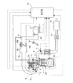
以下、この発明の好ましい実施の形態を図面に基づいて詳細に説明する。図1は、この発明に係る制御装置が適用された内燃機関のシステム構成図である。火花点火式ガソリン機関からなる内燃機関1は、吸気弁3と排気弁4とを有し、かつ、吸気弁3のリフト特性を連続的に変更可能な可変動弁装置2が設けられている。排気弁4側の動弁機構は、排気カムシャフト5により排気弁4を駆動する直動型のものであり、そのバルブリフト特性は常に一定である。
Hereinafter, preferred embodiments of the present invention will be described in detail with reference to the drawings. FIG. 1 is a system configuration diagram of an internal combustion engine to which a control device according to the present invention is applied. An
各気筒の排気を集合させる排気マニホルド6の出口側は触媒コンバータ7に接続されている。この触媒コンバータ7の上流位置には空燃比を検出するための空燃比センサ8が設けられている。触媒コンバータ7の下流側には第2の触媒コンバータ10および消音器11が設けられている。各気筒の吸気ポートに向かって各気筒毎に燃料を噴射供給するように燃料噴射弁12が配設されている。この吸気ポートにはブランチ通路15がそれぞれ接続されている。これら複数のブランチ通路15の上流端がコレクタ16に接続されている。このコレクタ16の一端には吸気入口通路17が接続されている。この吸気入口通路17には電子制御スロットル弁18が設けられている。これら吸気ポート,ブランチ通路15,コレクタ16及び吸気入口通路17等により吸気通路が構成されている。
The outlet side of the exhaust manifold 6 that collects the exhaust of each cylinder is connected to the catalytic converter 7. An air-
電子制御スロットル弁18は、電気モータからなるアクチュエータ18aを備え、エンジンコントロールユニット19から与えられる制御信号によって、そのスロットル開度が連続的に変更・制御される。例えば、スロットル弁18の実際の開度を検出するセンサ18bを一体に備えており、その検出信号に基づいて、スロットル開度TVOが目標開度にクローズドループ制御される。また、スロットル弁18の上流に、吸入空気流量を検出するエアフロメータ20が配置され、さらに上流にエアクリーナ21が設けられている。
The electronically controlled
機関回転速度(機関回転数)およびクランク角位置を検出するために、クランクシャフトに対してクランク角センサ22が設けられとともに、シリンダブロックの側壁には、エンジン振動を検出する振動センサ25が取り付けられている。更に、運転者により操作されるアクセルペダル開度(踏込量)を検出するアクセル開度センサ23を備えている。これらの検出信号は、上記のエアフロメータ20や空燃比センサ8等の検出信号とともに、エンジンコントロールユニット19に入力されている。エンジンコントロールユニット19では、これらの検出信号に基づいて、燃料噴射弁12の噴射量や噴射時期、点火プラグ24による点火時期、可変動弁装置2による吸気弁のリフト特性、スロットル弁18の開度、などを制御する。
In order to detect the engine speed (engine speed) and the crank angle position, a
上記の吸気弁3側の可変動弁装置2は、例えば特開2002−89341号公報等によって公知のものであり、図2に示すように、複数の気筒の吸気弁3のバルブリフト量及び作動角の双方を連続的に可変制御するリフト・作動角可変機構51と、複数の気筒の吸気弁の作動角の中心位相(クランクシャフトに対する位相)を連続的に進角もしくは遅角させる位相可変機構52と、が組み合わされて構成されている。このようにリフト・作動角可変機構51と位相可変機構52とを組み合わせた可変動弁装置2によれば、吸気弁開時期(IVO)および吸気弁閉時期(IVC)の双方をそれぞれ独立して任意に制御することが可能であり、かつ、低負荷域ではリフト量(最大リフト量)を小さくすることで、負荷に応じた吸入空気量に制限することができる。なお、リフト量がある程度大きな領域では、シリンダ内に流入する空気量が主に吸気弁3の開閉時期によって定まるのに対し、リフト量が十分に小さい状態では、主にリフト量によって空気量が定まる。
The
リフト・作動角可変機構51は、クランクシャフトに連動して回転する中空状の駆動軸53と、この駆動軸53に偏心して設けられた駆動偏心カム部55と、駆動軸53の斜め上方に平行に配置された制御軸56と、この制御軸56に偏心して設けられた制御偏心カム部57と、この制御偏心カム部57に揺動自在に取り付けられたロッカアーム58と、各吸気弁3上端のタペット(又はバルブリフタ)59に当接して吸気弁を開閉作動する揺動カム60と、を備えている。
The lift / operating
駆動軸53及び制御軸56は軸受ブラケット等を用いてシリンダヘッド側に回転可能に支持されている。駆動偏心カム部55とロッカアーム58の一端とは第1リンク61によって連係されている。第1リンク61は、その環状部61aが上記駆動偏心カム部55の外周面に回転可能に嵌合しており、かつ、延長部61bが上記ロッカアーム58の一端部に連係している。ロッカアーム58の他端と揺動カム60とは、第2リンク62によって連係されている。ロッカアーム58が回転可能に嵌合する制御偏心カム部57の円形の外周面は、制御軸56の軸心に対して偏心している。従って、制御軸56の角度位置に応じてロッカアーム58の揺動中心が変化する。
The
上記揺動カム60は、駆動軸53の外周に嵌合して回転自在に支持されており、側方へ延びた端部に、上記第2リンク62の下端部が連係している。この揺動カム60の下面には、駆動軸53と同心状の円弧をなす基円面と、該基円面から上記端部へと所定の曲線を描いて延びるカム面と、が連続して形成されている。上記基円面はリフト量が0となる区間であり、揺動カム60が揺動してカム面がタペット59に接触すると、徐々にリフトしていくことになる。
The
上記制御軸56は、一端部に設けられた例えば電動モータからなるリフト・作動角制御用アクチュエータ65によって、その回転位置が変更・保持される。このアクチュエータ65により例えば制御偏心カム部57の位置を変更することにより、揺動カム60の初期位置が変化し、吸気弁のバルブリフト量及び作動角の双方が変化する。制御偏心カム部57の初期位置は連続的に変化させ得るので、これに伴って、バルブリフト特性は連続的に変化する。つまり、リフトならびに作動角を、両者同時に、連続的に拡大,縮小させることができる。
The rotational position of the
位相可変機構52は、図2に示すように、上記駆動軸53の前端部に設けられたスプロケット71と、このスプロケット71と上記駆動軸53とを所定の角度範囲内において相対的に回転させる位相制御用油圧アクチュエータ72と、から構成されている。上記スプロケット71は、図示せぬタイミングチェーンもしくはタイミングベルトを介して、クランクシャフトに連動している。従って、上記位相制御用油圧アクチュエータ72への油圧制御によって、スプロケット71と駆動軸53とが相対的に回転し、リフト中心角が遅進する。つまり、リフト特性の曲線自体は変わらずに、全体が進角もしくは遅角する。
As shown in FIG. 2, the
これらリフト・作動角可変機構51ならびに位相可変機構52の制御としては、実際のリフト・作動角あるいは位相を検出するセンサを設けてクローズドループ制御するようにしても良く、あるいは運転条件に応じて単にオープンループ制御しても良い。
As the control of the lift / working
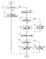
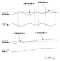
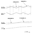
図3は、本発明の第1実施例に係る吸入空気量制御の流れを示すフローチャートである。本ルーチンは上記コントロールユニット19により所定期間毎に繰り返し実行される。図4は、この第1実施例に係る制御を適用したアイドル回転速度制御時におけるスロットル開度TVO及び吸気弁のバルブリフト量VLの変化を示すタイムチャートである。
FIG. 3 is a flowchart showing a flow of intake air amount control according to the first embodiment of the present invention. This routine is repeatedly executed by the
S(ステップ)1では、内燃機関がアイドル運転状態であるかを判定する。例えば、アクセル開度センサ23で検出されるアクセルペダル開度(踏込量)が0(零)、すなわちアクセルOFFであり、かつ、車速が所定値以下あるいはニュートラルスイッチがONである等の所定のアイドル条件が成立する場合に、アイドル運転状態であると判定される。
In S (step) 1, it is determined whether the internal combustion engine is in an idle operation state. For example, the accelerator pedal opening (depression amount) detected by the
例えばアクセルペダルが踏み込まれている車両走行中のように、アイドル運転時でない場合には、S1からS2へ進む。このS2では、スロットル弁18のスロットル開度TVOと、可変動弁装置2のリフト・作動角可変機構51による吸気弁のバルブリフト量VLと、を通常の目標値へ向けて制御する。具体的には、アクセル開度に基づいて要求トルクを演算し、この要求トルクに基づいて要求吸入空気量を演算し、この要求吸入空気量に基づいて(要求吸入空気量が得られるように)、スロットル開度の目標値と吸気弁のバルブリフト量(及び作動角)の目標値とを演算する。これらの目標値へ向けてスロットル弁18及びリフト・作動角可変機構51がそれぞれ駆動制御される。この制御は、上述したようにスロットルセンサ18bや制御軸センサの出力に基づくクローズドループ制御であっても良く、あるいは目標値へ向けたオープンループ制御であっても良い。
For example, when the vehicle is not running during idling, such as when the vehicle is running with the accelerator pedal depressed, the process proceeds from S1 to S2. In S2, the throttle opening degree TVO of the
アイドル運転時の場合には、S1からS3へ進み、機関回転速度Neの実回転速度rNeを読み込む。この実回転速度rNeは、一般的にはクランク角センサ22の検出信号等に基づいて演算される。
In the case of idling operation, the process proceeds from S1 to S3, and the actual rotational speed rNe of the engine rotational speed Ne is read. This actual rotational speed rNe is generally calculated based on a detection signal of the
S4〜S6では、実回転速度rNeと目標アイドル回転速度tNeとの偏差に基づくフィードバック制御により可変動弁装置2を制御する(第1アイドル制御手段)。フィードバック制御自体については公知であり、ここではリフト・作動角可変機構51の制御について簡単に説明すると、実回転速度rNeが目標アイドル回転速度tNeよりも大きい場合には、その偏差に基づいてバルブリフト量VLを低下側へ制御・操作し(S4→S5)、実回転速度rNeが目標アイドル回転速度tNe以下の場合には、その偏差に基づいてバルブリフト量VLを増加側へ制御・操作する(S4→S6)。上記の目標アイドル回転速度tNeは、エンジンコントロールユニット19により冷却水温や補機負荷等に基づいて設定される。
In S4 to S6, the
S7では、上記の実回転速度rNeに基づいて、平均回転速度avNeを演算する。この平均回転速度avNeは、実回転速度rNeを平滑化・平準化・なまし処理化した値であって、実回転速度rNeに対して長期的な値であり、例えば下記の一次遅れ式(1)により加重平均化することにより演算される。 In S7, the average rotational speed avNe is calculated based on the actual rotational speed rNe. The average rotation speed avNe is a value obtained by smoothing, leveling, and smoothing the actual rotation speed rNe, and is a long-term value with respect to the actual rotation speed rNe. ) To obtain a weighted average.
avNe=W・rNe+(1−W)rNez …(1)
「rNez」は、実回転速度rNeの前回値(一演算前の値)であり、「W」は、予め設定される1未満の加重値である。加重値Wが小さいほど、実回転速度rNeに対する遅れが大きくなり、rNeの変化に対する変動が緩慢となる。
avNe = W · rNe + (1−W) rNez (1)
“RNez” is the previous value (value before one calculation) of the actual rotational speed rNe, and “W” is a preset weight value less than 1. The smaller the weight value W, the greater the delay with respect to the actual rotational speed rNe, and the fluctuation with respect to the change in rNe becomes slow.
S8〜S10では、上記の平均回転速度avNeと目標アイドル回転速度tNeとの偏差に基づくフィードバック制御によりスロットル弁18を制御する(第2アイドル制御手段)。フィードバック制御自体については公知であり、簡単に説明すると、平均回転速度avNeが目標アイドル回転速度tNeよりも大きい場合には、その偏差に基づいてスロットル開度TVOを低下側つまり閉じる側へ制御・操作し(S8→S9)、平均回転速度avNeが目標アイドル回転速度tNe以下の場合には、その偏差に基づいてスロットル開度TVOを増加側つまり開く側へ制御・操作する(S8→S10)。
In S8 to S10, the
アイドル運転時に、仮にスロットル弁と可変動弁装置の双方を回転速度の偏差に基づいて同じようにフィードバック制御すると、それぞれの制御による回転速度変動の振動特性がほぼ同期して、上述したように機関回転速度が過度に上昇・低下する、いわゆる制御ハンチングを招くおそれがある。これに対して本実施例では、アイドル運転時に、一方のリフト・作動角可変機構51のフィードバック制御に実回転速度rNeを用い、他方のスロットル弁18のフィードバック制御には、この実回転速度rNeに対して一次遅れ処理を施した平均回転速度avNeを用いているので、図4にも示すように、フィードバック制御によるバルブリフト量VLとスロットル開度TVOとの変動・振動の周期が大きく異なるものとなる。つまり、短期的な値である実回転速度rNeを用いたバルブリフト量VLは、実回転速度rNeとほぼ同期するように相対的に短い周期で細かく増減・振動するのに対し、この実回転速度rNeに比して長期的な値であり、緩慢に変動する平均回転速度avNeを用いたスロットル開度TVOは、実回転速度rNeの変動とは全く異なる形で、相対的に長い周期で緩慢に変動することとなる。従って、上述したような機関回転速度が過度に上昇・低下する制御ハンチングを生じることがない。
During idle operation, if both the throttle valve and the variable valve system are feedback-controlled in the same way based on the deviation of the rotational speed, the vibration characteristics of the rotational speed fluctuations by the respective controls are almost synchronized, and the engine as described above. There is a risk of so-called control hunting, in which the rotational speed is excessively increased or decreased. On the other hand, in the present embodiment, during idle operation, the actual rotational speed rNe is used for feedback control of one lift / working
特に、この第1実施例では、バルブリフト量VLのような吸気弁のリフト特性の変更によるシリンダ吸入空気量の変化は非常に応答性に優れており、このバルブリフト量VLのフィードバック制御を、短期的な値である実回転速度rNeに基づいて行っているので、応答性にも優れている。 In particular, in the first embodiment, the change in the cylinder intake air amount due to the change in the lift characteristic of the intake valve such as the valve lift amount VL is very responsive, and the feedback control of the valve lift amount VL is performed. Since it is based on the actual rotational speed rNe, which is a short-term value, the responsiveness is also excellent.
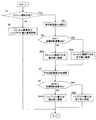
図5及び図6は、本発明の第2実施例に係るアイドル運転時の吸入空気量の制御の流れを示すフローチャート及びタイムチャートである。 5 and 6 are a flowchart and a time chart showing a flow of control of the intake air amount during idle operation according to the second embodiment of the present invention.
S1〜S3の処理は上記第1実施例と同様である。S4〜S6Aでは、実回転速度rNeと目標アイドル回転速度tNeとの偏差に基づくフィードバック制御により、スロットル弁18を制御する(第1アイドル制御手段)。簡単に説明すると、実回転速度rNeが目標アイドル回転速度tNeよりも大きい場合には、その偏差に基づいてスロットル開度TVOを低下側つまり閉じる側へ制御・操作し(S4→S5A)、実回転速度rNeが目標アイドル回転速度tNe以下の場合には、その偏差に基づいてスロットル開度TVOを増加側つまり開く側へ制御・操作する(S4→S6A)。
The processing of S1 to S3 is the same as that in the first embodiment. In S4 to S6A, the
S7では、第1実施例と同様、実回転速度rNeに基づいて平均回転速度avNeを演算する。S8〜S10では、上記の平均回転速度avNeと目標アイドル回転速度tNeとの偏差に基づくフィードバック制御により可変動弁装置2を制御する(第2アイドル制御手段)。簡単に説明すると、平均回転速度avNeが目標アイドル回転速度tNeよりも大きい場合には、その偏差に基づいてリフト・作動角可変機構51によるバルブリフト量VLを低下側へ制御・操作し(S8→S9A)、平均回転速度avNeが目標アイドル回転速度tNe以下の場合には、その偏差に基づいてバルブリフト量VLを増加側へ制御・操作する(S8→S10A)。
In S7, the average rotational speed avNe is calculated based on the actual rotational speed rNe, as in the first embodiment. In S8 to S10, the
このような第2実施例では、第1実施例と同様、一方のスロットル弁18のフィードバック制御に実回転速度rNeを用い、他方のリフト・作動角可変機構51のフィードバック制御には、この実回転速度rNeに対して一次遅れ処理を施した平均回転速度avNeを用いているので、図6にも示すように、両者のフィードバック制御による変動・振動の周期が大きく異なるものとなる。つまり、短期的な値である実回転速度rNeを用いたスロットル開度TVOは、実回転速度rNeとほぼ同期するように相対的に短い周期で細かく増減・振動するのに対し、長期的な値である平均回転速度avNeを用いたバルブリフト量VLは、実回転速度rNeの変動とは全く異なる形で、相対的に長い周期で緩慢に変動することとなる。従って、上述したような機関回転速度が過度に上昇・低下する制御ハンチングを生じることがない。
In the second embodiment, as in the first embodiment, the actual rotational speed rNe is used for feedback control of one
特に、この第2実施例では、リフト・作動角可変機構51に対して比較的緩慢なフィードバック制御が行われるので、その制御分解能が過度に要求されることがなく、コスト的に有利である。
In particular, in the second embodiment, since the relatively slow feedback control is performed on the lift / operating
以上のように本発明を具体的な実施例に基づいて説明してきたが、本発明は上記実施例に限定されるものではなく、その趣旨を逸脱しない範囲で、種々の変形・変更を含むものである。 As described above, the present invention has been described based on the specific embodiments. However, the present invention is not limited to the above-described embodiments, and includes various modifications and changes without departing from the spirit of the present invention. .
例えば可変動弁装置としては、上記実施例のようにリフト・作動角可変機構51と位相可変機構52とを併用するものに限らず、いずれか一方を単独で用いても良く、また、他の可変動弁機構、例えばカムシャフトに設けられた三次元形状のカムを有し、カムシャフトを軸方向に移動させることにより、リフト・作動角を連続的に変更する機構を用いても良い。また、上記実施例ではリフト・作動角可変機構51の制御パラメータとしてバルブリフト量VLを用いているが、代わりに吸気弁の作動角を用いても良い。
For example, the variable valve operating device is not limited to the combination of the lift / operating
以上の説明より把握し得る特徴的な技術思想について以下に列記する。 The characteristic technical ideas that can be grasped from the above description are listed below.
本発明に係る内燃機関の制御装置は、吸気弁3のリフト特性(バルブリフト量VL)を連続的に変更可能な可変動弁装置2と、吸気通路(17)に設けられたスロットル弁18と、を併用して吸入空気量を制御するものであって、内燃機関がアイドル運転状態であることを検出するアイドル判定手段(S1)と、内燃機関の実回転速度rNeを検出する回転速度検出手段(S3,クランク角センサ22)と、上記実回転速度rNeを平準化(加重平均化)した平均回転速度avNeを演算する平均回転速度演算手段(S7)と、を有する。
The control device for an internal combustion engine according to the present invention includes a
(1)そして、上記アイドル運転時に、上記実回転速度rNeと目標アイドル回転速度tNeとの偏差に基づくフィードバック制御により、上記スロットル弁18と可変動弁装置2の一方を制御する第1アイドル制御手段(S4〜S6,S4〜S6A)と、上記アイドル運転時に、上記平均回転速度avNeと目標アイドル回転速度tNeとの偏差に基づくフィードバック制御により、上記スロットル弁18と可変動弁装置2の他方を制御する第2アイドル制御手段(S8〜S10,S8〜S10A)と、を有することを特徴としている。
(1) First idle control means for controlling one of the
(2)上記アイドル運転時に、上記実回転速度rNeと目標アイドル回転速度tNeとの偏差に基づくフィードバック制御により、上記可変動弁装置2を制御する第1アイドル制御手段(S4〜S6)と、上記アイドル運転時に、上記平均回転速度avNeと目標アイドル回転速度tNeとの偏差に基づくフィードバック制御により、上記スロットル弁18を制御する第2アイドル制御手段(S8〜S10)と、を有することを特徴としている。
(2) During the idle operation, a first idle control means (S4 to S6) for controlling the
(3)上記アイドル運転時に、上記実回転速度rNeと目標アイドル回転速度tNeとの偏差に基づくフィードバック制御により、上記スロットル弁18を制御する第1アイドル制御手段(S4〜S6A)と、上記アイドル運転時に、上記平均回転速度avNeと目標アイドル回転速度tNeとの偏差に基づくフィードバック制御により、上記可変動弁装置2を制御する第2アイドル制御手段(S8〜S10A)と、を有することを特徴としている。
(3) During the idle operation, the first idle control means (S4 to S6A) for controlling the
(4)上記平均回転速度は、典型的には、下記の一次遅れ式により簡易に演算することができる。
avNe=W・rNe+(1−W)rNez
avNe…平均回転速度
rNe…実回転速度
rNez…実回転速度の前回値
W…加重値(1未満の定数)
(5)上記アイドル運転時に、上記実回転速度rNeと目標アイドル回転速度tNeとに基づいて上記スロットル弁18と可変動弁装置2の一方を制御する第1アイドル制御手段(S4〜S6,S4〜S6A)と、上記アイドル運転時に、上記実回転速度rNeと目標アイドル回転速度tNeとに基づいて、上記第1アイドル制御手段に比して長期的に、上記スロットル弁18と可変動弁装置2の他方を制御する第2アイドル制御手段(S8〜S10,S8〜S10A)と、を有することを特徴としている。
(4) Typically, the average rotation speed can be easily calculated by the following first-order lag equation.
avNe = W · rNe + (1−W) rNez
avNe: average rotational speed rNe: actual rotational speed rNez: previous value of actual rotational speed W: weighted value (constant less than 1)
(5) First idle control means (S4 to S6, S4 to S4) for controlling one of the
(6)好ましくは、上記可変動弁装置2が、吸気弁のバルブリフト量と作動角とを連続的に変更可能なリフト・作動角可変機構51を備え、このリフト・作動角可変機構41が、クランクシャフトに連動して回転する駆動軸53と、この駆動軸53に偏心して設けられた駆動偏心カム部55と、制御軸56と、この制御軸56に偏心して設けられた制御偏心カム部57と、この制御偏心カム部57に揺動可能に取り付けられたロッカアーム58と、吸気弁3を開閉作動する揺動カム60と、上記駆動偏心カム部55とロッカアーム58の一端とを連係する第1リンク61と、上記ロッカアーム58の他端と揺動カム60とを連係する第2リンク62と、上記制御軸56の回転位置を変更・保持するアクチュエータ65と、を有する。
(6) Preferably, the variable
このようなリフト・作動角可変機構51は、一般的な直動型固定動弁系のカムシャフト及び固定カムとほぼ同じ位置に駆動軸53及び揺動カム60を配置でき、かつ、駆動軸53の周囲に集約して配置できるため、コンパクトで機関搭載性に優れ、既存の内燃機関にも少ないレイアウトの変更で容易に適用できる。また、制御偏心カム部57とロッカアーム58との間の滑り軸受部のようにリンク要素の連結部位の多くが面接触となっており、かつ、リターンスプリング等による強制的な付勢手段を敢えて必要としないので、潤滑が容易で耐久性・信頼性にも優れている。
In such a lift / operating
1…内燃機関
2…可変動弁装置
3…吸気弁
18…電子制御スロットル弁
51…リフト・作動角可変機構
DESCRIPTION OF
Claims (6)
内燃機関がアイドル運転状態であることを検出するアイドル判定手段と、
内燃機関の実回転速度を検出する回転速度検出手段と、
上記実回転速度を平準化した平均回転速度を演算する平均回転速度演算手段と、
上記アイドル運転時に、上記実回転速度と目標アイドル回転速度との偏差に基づくフィードバック制御により、上記スロットル弁と可変動弁装置の一方を制御する第1アイドル制御手段と、
上記アイドル運転時に、上記平均回転速度と目標アイドル回転速度との偏差に基づくフィードバック制御により、上記スロットル弁と可変動弁装置の他方を制御する第2アイドル制御手段と、
を有することを特徴とする内燃機関の制御装置。 In a control device for an internal combustion engine that controls the intake air amount by using a variable valve device that can continuously change the lift characteristics of the intake valve and a throttle valve provided in the intake passage,
Idle determination means for detecting that the internal combustion engine is in an idle operation state;
A rotational speed detecting means for detecting an actual rotational speed of the internal combustion engine;
Average rotation speed calculating means for calculating an average rotation speed obtained by leveling the actual rotation speed;
A first idle control means for controlling one of the throttle valve and the variable valve gear by feedback control based on a deviation between the actual rotational speed and the target idle rotational speed during the idle operation;
A second idle control means for controlling the other of the throttle valve and the variable valve gear by feedback control based on a deviation between the average rotational speed and the target idle rotational speed during the idle operation;
A control apparatus for an internal combustion engine, comprising:
内燃機関がアイドル運転状態であることを検出するアイドル判定手段と、
内燃機関の実回転速度を検出する回転速度検出手段と、
上記実回転速度を加重平均化した平均回転速度を演算する平均回転速度演算手段と、
上記アイドル運転時に、上記実回転速度と目標アイドル回転速度との偏差に基づくフィードバック制御により、上記可変動弁装置を制御する第1アイドル制御手段と、
上記アイドル運転時に、上記平均回転速度と目標アイドル回転速度との偏差に基づくフィードバック制御により、上記スロットル弁を制御する第2アイドル制御手段と、
を有することを特徴とする内燃機関の制御装置。 In a control device for an internal combustion engine that controls the intake air amount by using a variable valve device that can continuously change the lift characteristics of the intake valve and a throttle valve provided in the intake passage,
Idle determination means for detecting that the internal combustion engine is in an idle operation state;
A rotational speed detecting means for detecting an actual rotational speed of the internal combustion engine;
Average rotation speed calculation means for calculating an average rotation speed obtained by weighted averaging the actual rotation speed;
A first idle control means for controlling the variable valve gear by feedback control based on a deviation between the actual rotational speed and the target idle rotational speed during the idle operation;
Second idle control means for controlling the throttle valve by feedback control based on a deviation between the average rotational speed and the target idle rotational speed during the idle operation;
A control apparatus for an internal combustion engine, comprising:
内燃機関がアイドル運転状態であることを検出するアイドル判定手段と、
内燃機関の実回転速度を検出する回転速度検出手段と、
上記実回転速度を加重平均化した平均回転速度を演算する平均回転速度演算手段と、
上記アイドル運転時に、上記実回転速度と目標アイドル回転速度との偏差に基づくフィードバック制御により、上記スロットル弁を制御する第1アイドル制御手段と、
上記アイドル運転時に、上記平均回転速度と目標アイドル回転速度との偏差に基づくフィードバック制御により、上記可変動弁装置を制御する第2アイドル制御手段と、
を有することを特徴とする内燃機関の制御装置。 In a control device for an internal combustion engine that controls the intake air amount by using a variable valve device that can continuously change the lift characteristics of the intake valve and a throttle valve provided in the intake passage,
Idle determination means for detecting that the internal combustion engine is in an idle operation state;
A rotational speed detecting means for detecting an actual rotational speed of the internal combustion engine;
Average rotation speed calculation means for calculating an average rotation speed obtained by weighted averaging the actual rotation speed;
First idle control means for controlling the throttle valve by feedback control based on a deviation between the actual rotational speed and the target idle rotational speed during the idle operation;
A second idle control means for controlling the variable valve gear by feedback control based on a deviation between the average rotational speed and the target idle rotational speed during the idle operation;
A control apparatus for an internal combustion engine, comprising:
avNe=W・rNe+(1−W)rNez
avNe…平均回転速度
rNe…実回転速度
rNez…実回転速度の前回値
W…加重値(1未満の定数)。 The control device for an internal combustion engine according to any one of claims 1 to 3, wherein the average rotation speed is calculated by a first-order lag equation described below;
avNe = W · rNe + (1−W) rNez
avNe: average rotation speed rNe: actual rotation speed rNez: previous value of actual rotation speed W: weighted value (constant less than 1)
内燃機関がアイドル運転状態であることを検出するアイドル判定手段と、
内燃機関の実回転速度を検出する回転速度検出手段と、
上記アイドル運転時に、上記実回転速度と目標アイドル回転速度とに基づいて上記スロットル弁と可変動弁装置の一方を制御する第1アイドル制御手段と、
上記アイドル運転時に、上記実回転速度と目標アイドル回転速度とに基づいて、上記第1アイドル制御手段に比して長期的に、上記スロットル弁と可変動弁装置の他方を制御する第2アイドル制御手段と、
を有することを特徴とする内燃機関の制御装置。 In a control device for an internal combustion engine that controls the intake air amount by using a variable valve device that can continuously change the lift characteristics of the intake valve and a throttle valve provided in the intake passage,
Idle determination means for detecting that the internal combustion engine is in an idle operation state;
A rotational speed detecting means for detecting an actual rotational speed of the internal combustion engine;
First idle control means for controlling one of the throttle valve and the variable valve gear based on the actual rotational speed and the target idle rotational speed during the idle operation;
Second idle control for controlling the other of the throttle valve and the variable valve operating device for a longer period of time than the first idle control means based on the actual rotational speed and the target idle rotational speed during the idle operation. Means,
A control apparatus for an internal combustion engine, comprising:
このリフト・作動角可変機構が、クランクシャフトに連動して回転する駆動軸と、この駆動軸に偏心して設けられた駆動偏心カム部と、制御軸と、この制御軸に偏心して設けられた制御偏心カム部と、この制御偏心カム部に揺動可能に取り付けられたロッカアームと、吸気弁を開閉作動する揺動カムと、上記駆動偏心カム部とロッカアームの一端とを連係する第1リンクと、上記ロッカアームの他端と揺動カムとを連係する第2リンクと、上記制御軸の回転位置を変更・保持するアクチュエータと、を有することを特徴とする請求項1〜4のいずれかに記載の内燃機関の制御装置。
The variable valve device includes a lift / operating angle variable mechanism capable of continuously changing the valve lift amount and the operating angle of the intake valve,
The lift / operating angle variable mechanism includes a drive shaft that rotates in conjunction with the crankshaft, a drive eccentric cam portion that is eccentrically provided on the drive shaft, a control shaft, and a control that is eccentrically provided on the control shaft. An eccentric cam portion, a rocker arm that is swingably attached to the control eccentric cam portion, a swing cam that opens and closes an intake valve, a first link that links the drive eccentric cam portion and one end of the rocker arm, 5. The apparatus according to claim 1, further comprising: a second link that links the other end of the rocker arm and a swing cam; and an actuator that changes and holds the rotational position of the control shaft. Control device for internal combustion engine.
Priority Applications (1)
| Application Number | Priority Date | Filing Date | Title |
|---|---|---|---|
| JP2004111714A JP2005291186A (en) | 2004-04-06 | 2004-04-06 | Control device for internal combustion engine |
Applications Claiming Priority (1)
| Application Number | Priority Date | Filing Date | Title |
|---|---|---|---|
| JP2004111714A JP2005291186A (en) | 2004-04-06 | 2004-04-06 | Control device for internal combustion engine |
Publications (1)
| Publication Number | Publication Date |
|---|---|
| JP2005291186A true JP2005291186A (en) | 2005-10-20 |
Family
ID=35324383
Family Applications (1)
| Application Number | Title | Priority Date | Filing Date |
|---|---|---|---|
| JP2004111714A Pending JP2005291186A (en) | 2004-04-06 | 2004-04-06 | Control device for internal combustion engine |
Country Status (1)
| Country | Link |
|---|---|
| JP (1) | JP2005291186A (en) |
Cited By (3)
| Publication number | Priority date | Publication date | Assignee | Title |
|---|---|---|---|---|
| JP4913866B2 (en) * | 2007-04-10 | 2012-04-11 | 北陸電気工業株式会社 | Sensitive sensor and manufacturing method thereof |
| JP2013072309A (en) * | 2011-09-27 | 2013-04-22 | Toyota Motor Corp | Control device for internal combustion engine |
| US9926858B2 (en) | 2015-09-23 | 2018-03-27 | Hyundai Motor Company | Control method using continuous variable valve duration apparatus |
-
2004
- 2004-04-06 JP JP2004111714A patent/JP2005291186A/en active Pending
Cited By (3)
| Publication number | Priority date | Publication date | Assignee | Title |
|---|---|---|---|---|
| JP4913866B2 (en) * | 2007-04-10 | 2012-04-11 | 北陸電気工業株式会社 | Sensitive sensor and manufacturing method thereof |
| JP2013072309A (en) * | 2011-09-27 | 2013-04-22 | Toyota Motor Corp | Control device for internal combustion engine |
| US9926858B2 (en) | 2015-09-23 | 2018-03-27 | Hyundai Motor Company | Control method using continuous variable valve duration apparatus |
Similar Documents
| Publication | Publication Date | Title |
|---|---|---|
| JP4168872B2 (en) | Control device for internal combustion engine | |
| JP3797119B2 (en) | Intake control device for internal combustion engine | |
| US6883476B1 (en) | Control system and method for an internal combustion engine | |
| JP3783589B2 (en) | Variable valve operating device for internal combustion engine | |
| JP4186613B2 (en) | Intake control device for internal combustion engine | |
| JP4103819B2 (en) | Variable valve operating device for internal combustion engine | |
| JP3933115B2 (en) | Intake control device for internal combustion engine | |
| JP2005307935A (en) | Variable valve operating system for multi-cylinder internal combustion engine | |
| JP3890476B2 (en) | Intake valve drive control device for internal combustion engine | |
| JP4036057B2 (en) | Intake valve drive control device for internal combustion engine | |
| JP4214766B2 (en) | Air-fuel ratio control device for internal combustion engine | |
| JP2005291186A (en) | Control device for internal combustion engine | |
| JP4165433B2 (en) | Control device for internal combustion engine | |
| JP4165432B2 (en) | Control device for internal combustion engine | |
| JP4206967B2 (en) | Valve control device for internal combustion engine | |
| JP4003567B2 (en) | Intake control device for internal combustion engine | |
| JP4020065B2 (en) | Control device for internal combustion engine | |
| JP4380499B2 (en) | Control device for internal combustion engine | |
| JP4254130B2 (en) | Variable valve operating device for internal combustion engine | |
| JP4063194B2 (en) | Idle speed control device for internal combustion engine | |
| JP4765379B2 (en) | Control device for internal combustion engine | |
| JP4103821B2 (en) | Intake control device for internal combustion engine | |
| JP3933007B2 (en) | Intake control device for internal combustion engine | |
| JP4735379B2 (en) | Control device for internal combustion engine | |
| JP4400402B2 (en) | Control device for internal combustion engine |
Legal Events
| Date | Code | Title | Description |
|---|---|---|---|
| A621 | Written request for application examination |
Free format text: JAPANESE INTERMEDIATE CODE: A621 Effective date: 20050829 |
|
| A977 | Report on retrieval |
Free format text: JAPANESE INTERMEDIATE CODE: A971007 Effective date: 20070628 |
|
| A131 | Notification of reasons for refusal |
Free format text: JAPANESE INTERMEDIATE CODE: A131 Effective date: 20070710 |
|
| A521 | Written amendment |
Free format text: JAPANESE INTERMEDIATE CODE: A523 Effective date: 20070906 |
|
| A02 | Decision of refusal |
Free format text: JAPANESE INTERMEDIATE CODE: A02 Effective date: 20080408 |
|
| A521 | Written amendment |
Free format text: JAPANESE INTERMEDIATE CODE: A523 Effective date: 20080603 |
|
| A911 | Transfer of reconsideration by examiner before appeal (zenchi) |
Free format text: JAPANESE INTERMEDIATE CODE: A911 Effective date: 20080613 |
|
| A912 | Removal of reconsideration by examiner before appeal (zenchi) |
Free format text: JAPANESE INTERMEDIATE CODE: A912 Effective date: 20080815 |
|
| A521 | Written amendment |
Free format text: JAPANESE INTERMEDIATE CODE: A523 Effective date: 20091228 |