JP2005291155A - Blower - Google Patents
Blower Download PDFInfo
- Publication number
- JP2005291155A JP2005291155A JP2004110075A JP2004110075A JP2005291155A JP 2005291155 A JP2005291155 A JP 2005291155A JP 2004110075 A JP2004110075 A JP 2004110075A JP 2004110075 A JP2004110075 A JP 2004110075A JP 2005291155 A JP2005291155 A JP 2005291155A
- Authority
- JP
- Japan
- Prior art keywords
- main body
- body box
- blower
- air
- suction port
- Prior art date
- Legal status (The legal status is an assumption and is not a legal conclusion. Google has not performed a legal analysis and makes no representation as to the accuracy of the status listed.)
- Granted
Links
Images
Landscapes
- Structures Of Non-Positive Displacement Pumps (AREA)
Abstract
【課題】 ショートサーキットの起こらない遠心式の送風機で構成される送風装置を得る。
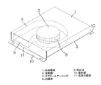
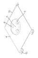
【解決手段】 内部にスクロールケーシング3を構成した本体箱体1、この本体箱体1に取付けられたモーター7によってスクロールケーシング3内で羽根車8が回転し、本体箱体1のモーター7側に形成された吸込口5からこれに隣接する側面に形成された吹出口9に向かう気流を形成する遠心式の送風機2からなり、吹出口9と吸込口5とを離隔する気流分離板11を設ける。また、本体箱体1の吸込口5側に吸込み風路空間を確保する取付脚10を設ける。さらには、本体箱体1の吸込口5の近傍に補助脚を設ける。
【選択図】 図1PROBLEM TO BE SOLVED: To obtain a blower constituted by a centrifugal blower in which a short circuit does not occur.
A main body box 1 having a scroll casing 3 therein, and a motor 7 attached to the main body box 1 rotate an impeller 8 in the scroll casing 3 so that the motor box 7 of the main body box 1 is moved to the motor 7 side. The centrifugal blower 2 that forms an air flow from the formed suction port 5 toward the blowout port 9 formed on the side surface adjacent to the suction port 5 is provided, and an airflow separation plate 11 that separates the blowout port 9 and the suction port 5 is provided. . Further, a mounting leg 10 that secures a suction air passage space is provided on the suction port 5 side of the main body box 1. Furthermore, an auxiliary leg is provided in the vicinity of the inlet 5 of the main body box 1.
[Selection] Figure 1
Description
本発明は、床面や天井面あるいは壁面などに設置して滞留する空気を攪拌し換気を促進する遠心式の送風機により構成された送風装置に関するものである。 The present invention relates to an air blower configured by a centrifugal blower that is installed on a floor surface, a ceiling surface, a wall surface, or the like to stir air staying and promote ventilation.
床面や天井面などに設置して滞留する空気を攪拌し換気を促進する送風装置としては、設置場所の制約を本体を支持する脚部の工夫により解消した例えば、特許文献1に示されたようなものがある。
As a blower device that stirs air that stays on the floor surface or ceiling surface and stirs up the air and promotes ventilation, for example,
従来のこの種の送風装置は、本体を支持する脚部が伸縮可能で、その台座部が回転できるようになっていて、凹凸のある所でも、吊り下げたり設置したりすることができるようになっている。しかしながら、本体の取付け側の反対面に吸込口が有り、吹出口が吸込口に近接した外周に設けられているため、吹出された空気が吸込口から吸込まれるといったショートサーキットが起き易い。また、吸込量を確保するため大きく開放された吸込口には異物の吸込みを防止するネットが設けられ、例えば、床に設けられた配線溝等に設置すれば、ネットが踏まれることになり、使用に供せない。 In this type of conventional blower, the legs that support the main body can be expanded and contracted, and the pedestal can be rotated so that it can be hung and installed even in uneven areas. It has become. However, since there is a suction port on the surface opposite to the attachment side of the main body and the air outlet is provided on the outer periphery close to the air inlet, a short circuit in which the blown air is sucked from the air inlet is likely to occur. In addition, a net that prevents the inhalation of foreign substances is provided at the suction port that is widely opened to ensure the amount of suction.For example, if installed in a wiring groove provided on the floor, the net will be stepped on. Cannot be used.
本発明は、上記した問題を解決するためになされたものであり、その目的とするところは、ショートサーキットの起こらない遠心式の送風機で構成される送風装置を得ることであり、床でも天井でも壁でも設置するだけで、必要な吸込み空間が確保でき、吸込口への異物の侵入も防止できる送風装置を得ることである。 The present invention has been made in order to solve the above-described problems, and the object of the present invention is to obtain a blower composed of a centrifugal blower that does not cause a short circuit. It is to obtain a blower device that can secure a necessary suction space only by installing it on a wall and can prevent foreign matter from entering the suction port.
上記課題を解決するために本発明は、内部にスクロールケーシングを構成した本体箱体に取付けられたモーターによってスクロールケーシング内で羽根車が回転し、本体箱体のモーター側に形成された吸込口からこれに隣接する側面に形成された吹出口に向かう気流を形成する遠心式の送風機からなる送風装置について、吹出口と吸込口とを離隔する気流分離板を設ける手段を採用する。 In order to solve the above-mentioned problems, the present invention provides a motor that is mounted on a main body box that forms a scroll casing therein, and an impeller is rotated in the scroll casing, and a suction port formed on the motor side of the main body box. About the air blower which consists of a centrifugal blower which forms the airflow which goes to the blower outlet formed in the side surface adjacent to this, the means which provides the airflow separation board which separates a blower outlet and a suction inlet is employ | adopted.
本発明によれば、吹出口と吸込口とは気流分離板で離隔されているため、吹出口から吹出された気流が再度吸込口から吸込まれるといったショートサーキットは起こらない。 According to the present invention, since the air outlet and the suction port are separated by the airflow separation plate, a short circuit in which the airflow blown from the air outlet is sucked again from the air inlet does not occur.
本発明の送風装置は、薄形の方形の本体箱体内に遠心式の送風機が組込まれて構成されている。本体箱体は鋼板製で内部にスクロールケーシングが構成され、本体箱体の底板中央に吸込口が設けられている。吸込口には支持脚によりモーターが取付けられ、このモーターの回転軸にスクロールケーシング内で回転する羽根車が装着されている。送風機の吹出口は、吸込口に隣接する側面に設けられ、本体箱体の吹出口以外の周側面は閉止されている。本体箱体の吹出口の臨む側面の下部は、本体箱体の底板より突出した取付脚で閉止されている。反対側の側面にも本体箱体の底板より突出す二個の取付脚がある。吹出口の臨む側面側の取付脚は、一連のアングル形をなし、設置用のネジ挿通孔が両端に設けられている。この取付脚の一部は、側面を閉止する部分とともに吹出口と吸込口とを離隔する気流分離板を構成している。この三つの取付脚により、本体箱体の吸込口側には三方の開放した吸込み風路空間が確保される。 The blower of the present invention is configured by incorporating a centrifugal blower into a thin rectangular main body box. The main body box is made of a steel plate, a scroll casing is formed inside, and a suction port is provided at the center of the bottom plate of the main body box. A motor is attached to the suction port by a support leg, and an impeller that rotates within the scroll casing is mounted on the rotation shaft of the motor. The blower outlet of the blower is provided on a side surface adjacent to the suction port, and the peripheral side surface other than the outlet of the main body box is closed. The lower part of the side facing the air outlet of the main body box is closed by mounting legs protruding from the bottom plate of the main body box. There are also two mounting legs protruding from the bottom plate of the main body box on the opposite side. The mounting leg on the side facing the air outlet has a series of angled shapes, and screw insertion holes for installation are provided at both ends. A part of this mounting leg constitutes an airflow separation plate that separates the air outlet and the suction port together with the portion that closes the side surface. With these three mounting legs, three open air intake passage spaces are secured on the suction port side of the main body box.
この送風装置は設置場所に取付脚によって取付けるだけで、三方の開放した吸込み風路空間が確保され、吸込み風路空間を通じて本体箱体の下面の吸込口から吸込まれた空気は、吹出口から半径方向に吹出される。吹出口と吸込口とは気流分離板で離隔されているのでショートサーキットは起こらない。吸込口は、設置面に向合うことになり、異物が入り込むことも少ない。また、本体箱体の上面は、フラットで例えば、床に設置した場合、踏み付けても支障は来さない。 By simply attaching the blower to the installation location with the mounting legs, three open suction air passage spaces are secured, and the air sucked from the suction port on the lower surface of the main body box through the suction air passage space is Blown in the direction. Since the air outlet and the air inlet are separated by the airflow separation plate, no short circuit occurs. The suction port faces the installation surface, and foreign objects are less likely to enter. Further, the upper surface of the main body box is flat and, for example, when installed on the floor, it does not hinder even if it is stepped on.
実施の形態1.
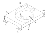
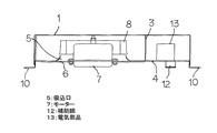
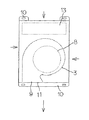
図1は、本実施の形態の送風装置の斜視図、図2は、同じく反対側から見た送風装置の斜視図、図3は、送風装置の断面図、図4は、同じく平面図、図5は、本体箱体の底板を示す斜視図、図6は、設置状態の一例を示す送風装置の略体側面図である。図7は、他の設置状態の一例を示す送風装置の略体側面図である。
1 is a perspective view of the blower device of the present embodiment, FIG. 2 is a perspective view of the blower device viewed from the opposite side, FIG. 3 is a sectional view of the blower device, and FIG. 4 is a plan view of the same. 5 is a perspective view showing the bottom plate of the main body box, and FIG. 6 is a schematic side view of the blower showing an example of the installation state. FIG. 7 is a schematic side view of an air blower illustrating an example of another installation state.
この送風装置は、薄形の方形の本体箱体1内に遠心式(シロッコファンやターボファン等)の送風機2が組込まれて構成されている。本体箱体1は鋼板製で内部にスクロールケーシング3が構成され、本体箱体1の底板4の中央に吸込口5が設けられている。吸込口5には支持脚6によりモーター7が取付けられ、このモーター7の回転軸にスクロールケーシング3内で回転する羽根車8が装着されている。送風機2の吹出口9は、吸込口5に隣接する側面に設けられ、本体箱体1の吹出口9以外の周側面は閉止されている(図1、図2参照)。本体箱体1の吹出口9の臨む側面の下部は、本体箱体1の底板4より突出した取付脚10で閉止されている。反対側の側面にも本体箱体1の底板4より突出す二個の取付脚10がある。吹出口9の臨む側面側の取付脚10は、一連のアングル形をなし、設置用のネジ挿通孔が両端に設けられている。この取付脚10の一部は、側面を閉止する部分とともに吹出口9と吸込口5とを離隔する気流分離板11を構成している。この三つの取付脚10により、本体箱体1の吸込口5側には三方の開放した吸込み風路空間が確保される。本体箱体1の底板4の下面には、二個の取付脚10間の吸込み風路空間から吸込まれる空気の抵抗にならない取付姿勢でアングル形の補助脚12が設けられている(図5参照)。本体箱体1内のスクロールケーシング3の外側には電気部品13が収められ、電気部品13の損傷や破壊が防止されている(図3参照)。
This blower is constructed by incorporating a centrifugal blower 2 (such as a sirocco fan or a turbo fan) into a thin rectangular
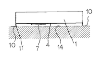
この送風装置は設置場所に取付脚10によって取付けるだけで、三方の開放した吸込み風路空間が本体箱体1の底板4と設置面14との間に図6に示すように確保され、吸込み風路空間を通じて本体箱体1の下面の吸込口5から吸込まれた空気は、吹出口9から半径方向に吹出される。これにより、室内に滞留する空気を攪拌し換気を促進することができる。吹出口9と吸込口5とは気流分離板11で離隔されているので吹出し気流と吸込み気流間でのショートサーキットは起こらない。吸込口5は、設置面14に向き合うことになり、異物が入り込むことも少ない。設置場所が、壁面や天井面であっても同様に機能する。また、本体箱体1の上面は、フラットで例えば、床に設置した場合、踏み付けても支障は来さない。補助脚12は、このように上からの荷重に対する耐力を備えさせるためのものであり、一本でも二本でもよい。
By simply attaching the blower to the installation place with the
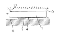
なお、図7に示すように、取付脚10を本体箱体1の天面に上向きに設けてもよい。これにより設置場所についての自由度が増す。
In addition, as shown in FIG. 7, the
1 本体箱体、 2 送風機、 3 スクロールケーシング、 5 吸込口、 7 モーター、 8 羽根車、 9 吹出口、 10 取付脚、 11 気流分離板、 12 補助脚、 13 電気部品。
DESCRIPTION OF
Claims (5)
Priority Applications (1)
| Application Number | Priority Date | Filing Date | Title |
|---|---|---|---|
| JP2004110075A JP4554256B2 (en) | 2004-04-02 | 2004-04-02 | Blower |
Applications Claiming Priority (1)
| Application Number | Priority Date | Filing Date | Title |
|---|---|---|---|
| JP2004110075A JP4554256B2 (en) | 2004-04-02 | 2004-04-02 | Blower |
Publications (2)
| Publication Number | Publication Date |
|---|---|
| JP2005291155A true JP2005291155A (en) | 2005-10-20 |
| JP4554256B2 JP4554256B2 (en) | 2010-09-29 |
Family
ID=35324356
Family Applications (1)
| Application Number | Title | Priority Date | Filing Date |
|---|---|---|---|
| JP2004110075A Expired - Fee Related JP4554256B2 (en) | 2004-04-02 | 2004-04-02 | Blower |
Country Status (1)
| Country | Link |
|---|---|
| JP (1) | JP4554256B2 (en) |
Cited By (2)
| Publication number | Priority date | Publication date | Assignee | Title |
|---|---|---|---|---|
| US8812513B2 (en) | 2009-12-25 | 2014-08-19 | International Business Machines Corporation | Hash pointer checking for hierarchical database logical relationship |
| JP2018168702A (en) * | 2017-03-29 | 2018-11-01 | 三菱電機株式会社 | Blower |
Citations (12)
| Publication number | Priority date | Publication date | Assignee | Title |
|---|---|---|---|---|
| JPS4725167Y1 (en) * | 1970-03-23 | 1972-08-07 | ||
| JPS599238U (en) * | 1982-07-09 | 1984-01-20 | 株式会社東芝 | Hot air machine |
| JPS59191527U (en) * | 1983-06-06 | 1984-12-19 | 三菱電機株式会社 | circulator |
| JPS61175600U (en) * | 1985-04-19 | 1986-11-01 | ||
| JPS61175598U (en) * | 1985-04-19 | 1986-11-01 | ||
| JPH01153440U (en) * | 1988-04-18 | 1989-10-23 | ||
| JP2000274767A (en) * | 1999-03-24 | 2000-10-06 | Asahi Solar Kogyo Kk | Underfloor air guiding assisting device |
| JP2001082780A (en) * | 1999-09-09 | 2001-03-30 | Sharp Corp | Underfloor ventilation |
| JP2001317485A (en) * | 2000-05-08 | 2001-11-16 | Mitsuya Soufuuki Seisakusho:Kk | Centrifugal air blower |
| JP2002349921A (en) * | 2001-05-22 | 2002-12-04 | Nippon Kobunshi Kk | Air agitator |
| JP2002364597A (en) * | 2001-06-11 | 2002-12-18 | Nippon Kobunshi Kk | Air stirring device |
| JP2003302085A (en) * | 2002-04-05 | 2003-10-24 | Cosmo Denki Kk | Ventilator |
-
2004
- 2004-04-02 JP JP2004110075A patent/JP4554256B2/en not_active Expired - Fee Related
Patent Citations (12)
| Publication number | Priority date | Publication date | Assignee | Title |
|---|---|---|---|---|
| JPS4725167Y1 (en) * | 1970-03-23 | 1972-08-07 | ||
| JPS599238U (en) * | 1982-07-09 | 1984-01-20 | 株式会社東芝 | Hot air machine |
| JPS59191527U (en) * | 1983-06-06 | 1984-12-19 | 三菱電機株式会社 | circulator |
| JPS61175600U (en) * | 1985-04-19 | 1986-11-01 | ||
| JPS61175598U (en) * | 1985-04-19 | 1986-11-01 | ||
| JPH01153440U (en) * | 1988-04-18 | 1989-10-23 | ||
| JP2000274767A (en) * | 1999-03-24 | 2000-10-06 | Asahi Solar Kogyo Kk | Underfloor air guiding assisting device |
| JP2001082780A (en) * | 1999-09-09 | 2001-03-30 | Sharp Corp | Underfloor ventilation |
| JP2001317485A (en) * | 2000-05-08 | 2001-11-16 | Mitsuya Soufuuki Seisakusho:Kk | Centrifugal air blower |
| JP2002349921A (en) * | 2001-05-22 | 2002-12-04 | Nippon Kobunshi Kk | Air agitator |
| JP2002364597A (en) * | 2001-06-11 | 2002-12-18 | Nippon Kobunshi Kk | Air stirring device |
| JP2003302085A (en) * | 2002-04-05 | 2003-10-24 | Cosmo Denki Kk | Ventilator |
Cited By (2)
| Publication number | Priority date | Publication date | Assignee | Title |
|---|---|---|---|---|
| US8812513B2 (en) | 2009-12-25 | 2014-08-19 | International Business Machines Corporation | Hash pointer checking for hierarchical database logical relationship |
| JP2018168702A (en) * | 2017-03-29 | 2018-11-01 | 三菱電機株式会社 | Blower |
Also Published As
| Publication number | Publication date |
|---|---|
| JP4554256B2 (en) | 2010-09-29 |
Similar Documents
| Publication | Publication Date | Title |
|---|---|---|
| JP2008223563A (en) | Axial fan device, axial impeller and electronic equipment | |
| US20080145246A1 (en) | Fan and fan housing thereof having flapper | |
| JP2006336642A (en) | Centrifugal fan and its frame | |
| JP4554256B2 (en) | Blower | |
| CN212548868U (en) | Filter device | |
| JP2001295785A (en) | Cross flow fan with protective net | |
| JPH10270879A (en) | Electronic equipment cooling structure | |
| JP2009127612A (en) | Venturi structure of fan motor | |
| JP2003097821A (en) | Air conditioner | |
| JP4724101B2 (en) | Blower | |
| CN111888876A (en) | Filter device | |
| CN102562624A (en) | Fan combination | |
| JP4670273B2 (en) | Duct fan | |
| JP2024119651A (en) | Built-in ventilation fan | |
| CN109424569B (en) | ventilation device | |
| JPH04288429A (en) | Duct ventilation fan | |
| JP3021457B2 (en) | Blower | |
| JP4503323B2 (en) | Ventilation equipment | |
| JP4300666B2 (en) | Floor-mounted air conditioner | |
| JP7678251B1 (en) | Ventilator mounting fixture | |
| CN110474466A (en) | Motor installation mechanism, fresh air components and air conditioners | |
| JP3062198B2 (en) | Vehicle blower | |
| JP2022045028A (en) | Blower | |
| JP2005274026A (en) | Ventilating fan | |
| JPH02136600A (en) | Ventilating fan |
Legal Events
| Date | Code | Title | Description |
|---|---|---|---|
| A621 | Written request for application examination |
Free format text: JAPANESE INTERMEDIATE CODE: A621 Effective date: 20061026 |
|
| RD01 | Notification of change of attorney |
Free format text: JAPANESE INTERMEDIATE CODE: A7421 Effective date: 20080220 |
|
| A977 | Report on retrieval |
Free format text: JAPANESE INTERMEDIATE CODE: A971007 Effective date: 20100127 |
|
| A131 | Notification of reasons for refusal |
Free format text: JAPANESE INTERMEDIATE CODE: A131 Effective date: 20100209 |
|
| A521 | Written amendment |
Free format text: JAPANESE INTERMEDIATE CODE: A523 Effective date: 20100409 |
|
| TRDD | Decision of grant or rejection written | ||
| A01 | Written decision to grant a patent or to grant a registration (utility model) |
Free format text: JAPANESE INTERMEDIATE CODE: A01 Effective date: 20100713 |
|
| A01 | Written decision to grant a patent or to grant a registration (utility model) |
Free format text: JAPANESE INTERMEDIATE CODE: A01 |
|
| A61 | First payment of annual fees (during grant procedure) |
Free format text: JAPANESE INTERMEDIATE CODE: A61 Effective date: 20100714 |
|
| FPAY | Renewal fee payment (event date is renewal date of database) |
Free format text: PAYMENT UNTIL: 20130723 Year of fee payment: 3 |
|
| R150 | Certificate of patent or registration of utility model |
Free format text: JAPANESE INTERMEDIATE CODE: R150 |
|
| R250 | Receipt of annual fees |
Free format text: JAPANESE INTERMEDIATE CODE: R250 |
|
| R250 | Receipt of annual fees |
Free format text: JAPANESE INTERMEDIATE CODE: R250 |
|
| R250 | Receipt of annual fees |
Free format text: JAPANESE INTERMEDIATE CODE: R250 |
|
| LAPS | Cancellation because of no payment of annual fees |