JP2005291138A - Canister purge control device for internal combustion engine - Google Patents
Canister purge control device for internal combustion engine Download PDFInfo
- Publication number
- JP2005291138A JP2005291138A JP2004109574A JP2004109574A JP2005291138A JP 2005291138 A JP2005291138 A JP 2005291138A JP 2004109574 A JP2004109574 A JP 2004109574A JP 2004109574 A JP2004109574 A JP 2004109574A JP 2005291138 A JP2005291138 A JP 2005291138A
- Authority
- JP
- Japan
- Prior art keywords
- fuel
- canister
- evaporated
- engine
- evaporation concentration
- Prior art date
- Legal status (The legal status is an assumption and is not a legal conclusion. Google has not performed a legal analysis and makes no representation as to the accuracy of the status listed.)
- Pending
Links
Images


Landscapes
- Supplying Secondary Fuel Or The Like To Fuel, Air Or Fuel-Air Mixtures (AREA)
Abstract
【課題】
燃料タンクで蒸発した燃料を貯蔵するキャニスタと、貯蔵した蒸発燃料を機関吸気管に放出するパージバルブと、放出される蒸発燃料のHC濃度を検出するエバポ濃度センサと、検出されたエバポ濃度に応じて機関燃料噴射量を制御する内燃機関において、液化した蒸発燃料によるエバポ濃度センサの特性変化,変質および腐食を防止することができる内燃機関のキャニスタパージ制御装置を提供する。
【解決手段】
上記課題はエバポ濃度センサの設置位置を、蒸発燃料を貯蔵するキャニスタより上方とすること、または蒸発燃料を機関吸気管に放出するパージバルブより上方とすること、または、機関吸気管への放出場所よりも上方とすること、または、さらに液化燃料を燃料タンクに循環させる配管をエバポ濃度センサより下方に設置することにより解決される。
【選択図】図1
【Task】
A canister that stores fuel evaporated in the fuel tank, a purge valve that discharges the stored evaporated fuel to the engine intake pipe, an evaporation concentration sensor that detects the HC concentration of the evaporated fuel, and a detected concentration according to the detected evaporation concentration Provided is an internal combustion engine canister purge control device capable of preventing characteristic change, alteration and corrosion of an evaporation concentration sensor due to liquefied evaporated fuel in an internal combustion engine which controls engine fuel injection amount.
[Solution]
The above problem is that the evaporative concentration sensor is installed above the canister that stores the evaporated fuel, or above the purge valve that discharges the evaporated fuel to the engine intake pipe, or from the discharge location to the engine intake pipe. Or by installing a pipe for circulating the liquefied fuel to the fuel tank below the evaporation concentration sensor.
[Selection] Figure 1
Description
本発明は内燃機関のキャニスタパージ制御装置に係り、蒸発燃料のHC濃度を検出するセンサの動作不良や、変質を防止し得るセンサ配置に関する。 The present invention relates to a canister purge control device for an internal combustion engine, and relates to a sensor arrangement that can prevent malfunction and deterioration of a sensor that detects the HC concentration of evaporated fuel.
一般に内燃機関には、燃料噴射弁による燃料供給のほか、燃料タンク内で発生する蒸発燃料(エバポガス)を吸気系に放出して供給するエバポパージ処理を行うものがある。該エバポパージ処理は、前記エバポガスをキャニスタに回収・吸着させた後、該キャニスタに外気を導入することによって前記吸気系に放出することが知られている。 In general, some internal combustion engines perform not only fuel supply by a fuel injection valve but also vapor purge processing for releasing and supplying evaporated fuel (evaporative gas) generated in a fuel tank to an intake system. In the evaporative purge process, it is known that after the evaporative gas is collected and adsorbed by the canister, the outside air is introduced into the canister and then released to the intake system.
そして、この場合には、前記エバポパージ処理による燃料と、前記燃料噴射弁による燃料とを合わせた空燃比制御が必要であることから、前記エバポガスのHC濃度を考慮したパージ制御装置に関する技術が各種成案されている。 In this case, since the air-fuel ratio control in which the fuel by the evaporation purge process and the fuel by the fuel injection valve are combined is necessary, various technologies relating to the purge control device in consideration of the HC concentration of the evaporation gas are proposed. Has been.
例えば、燃料タンク内で発生する蒸発燃料を貯蔵するキャニスタと、キャニスタ内に保持されている蒸発燃料を燃料噴射弁の上流に放出する機構を備え、燃料噴射弁上流に酸素濃度センサを備えている。この内燃機関では酸素濃度センサより、吸気通路内の蒸発燃料のエバポ濃度が検出される。検出されたエバポ濃度に基づいて、燃料噴射量を制御することで、蒸発燃料の影響を低減させている(例えば、特許文献1参照)。 For example, a canister for storing the evaporated fuel generated in the fuel tank, a mechanism for releasing the evaporated fuel held in the canister upstream of the fuel injection valve, and an oxygen concentration sensor upstream of the fuel injection valve are provided. . In this internal combustion engine, the evaporation concentration of the evaporated fuel in the intake passage is detected by the oxygen concentration sensor. The influence of the evaporated fuel is reduced by controlling the fuel injection amount based on the detected evaporation concentration (see, for example, Patent Document 1).
さらに、キャニスタと吸気管を結ぶパージ通路にエバポ濃度センサを設置し、パージ通路から機関吸気管に放出される蒸発燃料が機関吸入空気量に対して一定の比率になるように蒸発燃料の放出量を制御し、機関空燃比が該センサの上方を用いて機関空燃比が目標値になるように燃料噴射量を補正している(例えば、特許文献2参照)。 Furthermore, an evaporation concentration sensor is installed in the purge passage connecting the canister and the intake pipe, and the amount of evaporated fuel released so that the amount of evaporated fuel released from the purge passage to the engine intake pipe becomes a constant ratio to the amount of engine intake air. And the fuel injection amount is corrected so that the engine air-fuel ratio becomes the target value using the upper part of the sensor (see, for example, Patent Document 2).
このように、機関吸気管の放出される蒸発燃料のエバポに応じて燃料噴射量を精度よく制御する為には、蒸発燃料のエバポ濃度センサを用いることが必要であるが、運転状態や、機関周辺環境によっては蒸発した燃料がパージ通路内で、冷却され液化することがある。また一般的にセンサはガソリン等の燃料に長時間接触すると、特性変化や、変質,腐食などの恐れがある。 As described above, in order to accurately control the fuel injection amount in accordance with the evaporation fuel evaporated from the engine intake pipe, it is necessary to use the evaporation fuel evaporation concentration sensor. Depending on the surrounding environment, the evaporated fuel may be cooled and liquefied in the purge passage. In general, when a sensor is in contact with a fuel such as gasoline for a long time, there is a risk of characteristic change, alteration, corrosion, and the like.
ところで、前記のエバポ濃度センサを用いたパージ制御装置は、いずれも液化した蒸発燃料によるセンサの保護に対して格別の配慮がされていない。 By the way, none of the purge control devices using the above-mentioned evaporation concentration sensor give special consideration to the protection of the sensor by the liquefied evaporated fuel.
本発明は、このような問題に鑑みてなされたものであって、その目的とするところは、該センサとキャニスタおよびパージバルブ等のパージ配管の取り付け位置を最適化することで、液化した蒸発燃料による該センサの特性変化,変質および破損を防止することができる内燃機関のキャニスタパージ制御装置を提供することにある。 The present invention has been made in view of such a problem, and an object of the present invention is to optimize the attachment positions of the sensors and the purge pipes such as the canister and the purge valve so that the liquefied evaporated fuel is used. An object of the present invention is to provide a canister purge control device for an internal combustion engine that can prevent characteristic change, alteration and breakage of the sensor.
上記目的は、「燃料タンクで蒸発した燃料を貯蔵するキャニスタと、貯蔵した蒸発燃料を機関吸気管に放出するパージバルブと、放出される蒸発燃料のHC濃度を検出するエバポ濃度センサと、検出されたエバポ濃度に応じて機関燃料噴射量を制御する内燃機関において、エバポ濃度センサを前記キャニスタより上方に設置することを特徴としたキャニスタパージ装置」によっても達成される。また上記目的は、「燃料タンクで蒸発した燃料を貯蔵するキャニスタと、貯蔵した蒸発燃料を機関吸気管に放出するパージバルブと、放出される蒸発燃料のHC濃度を検出するエバポ濃度センサと、検出されたエバポ濃度に応じて機関燃料噴射量を制御する内燃機関において、エバポ濃度センサをパージバルブよりも上方に設置することを特徴としたキャニスタパージ装置」によっても達成される。また上記目的は、「燃料タンクで蒸発した燃料を貯蔵するキャニスタと、貯蔵した蒸発燃料を機関吸気管に放出するパージバルブと、放出される蒸発燃料のHC濃度を検出するエバポ濃度センサと、検出されたエバポ濃度に応じて機関燃料噴射量を制御する内燃機関において、エバポ濃度センサを蒸発燃料の機関吸気管の放出部よりも上方に設置することを特徴としたキャニスタパージ装置」によっても達成される。また上記目的は、「燃料タンクで蒸発した燃料を貯蔵するキャニスタと、貯蔵した蒸発燃料を機関吸気管に放出するパージバルブと、放出される蒸発燃料のHC濃度を検出するエバポ濃度センサと、検出されたエバポ濃度に応じて機関燃料噴射量を制御する内燃機関において、キャニスタから機関吸気管への放出部内で液化した蒸発燃料を機関燃料タンクへ循環させる手段を設けた、内燃機関のキャニスタパージ装置」によっても達成される。 The above-mentioned object is “a canister that stores fuel evaporated in a fuel tank, a purge valve that discharges the stored evaporated fuel to the engine intake pipe, an evaporation concentration sensor that detects the HC concentration of the evaporated fuel that has been detected, In an internal combustion engine that controls the engine fuel injection amount in accordance with the evaporation concentration, this can also be achieved by a canister purge device characterized in that an evaporation concentration sensor is installed above the canister. In addition, the above-mentioned object is “detected by a canister for storing fuel evaporated in the fuel tank, a purge valve for discharging the stored evaporated fuel to the engine intake pipe, and an evaporation concentration sensor for detecting the HC concentration of the released evaporated fuel. In an internal combustion engine that controls the engine fuel injection amount in accordance with the evaporation concentration, it is also achieved by a canister purge device characterized in that the evaporation concentration sensor is installed above the purge valve. In addition, the above-mentioned object is “detected by a canister for storing fuel evaporated in the fuel tank, a purge valve for discharging the stored evaporated fuel to the engine intake pipe, and an evaporation concentration sensor for detecting the HC concentration of the released evaporated fuel. In the internal combustion engine that controls the engine fuel injection amount according to the evaporation concentration, the canister purge device is characterized in that the evaporation concentration sensor is installed above the discharge portion of the engine intake pipe for the evaporated fuel. . In addition, the above-mentioned object is “detected by a canister for storing fuel evaporated in the fuel tank, a purge valve for discharging the stored evaporated fuel to the engine intake pipe, and an evaporation concentration sensor for detecting the HC concentration of the released evaporated fuel. In the internal combustion engine that controls the engine fuel injection amount according to the evaporation concentration, a canister purge device for an internal combustion engine provided with means for circulating the evaporated fuel liquefied in the discharge part from the canister to the engine intake pipe to the engine fuel tank. Is also achieved.
本発明の内燃機関のキャニスタパージ制御装置によれば、パージ内にて液化した蒸発燃料をエバポ濃度センサ部に滞留することがないように、該センサの取り付け位置をキャニスタより上方に取り付けるなどの配慮により、該センサの特性変化や、腐食するのを防止することができる。 According to the canister purge control device for an internal combustion engine of the present invention, consideration is given to mounting the mounting position of the sensor above the canister so that the evaporated fuel liquefied in the purge does not stay in the evaporation concentration sensor section. Therefore, it is possible to prevent characteristic changes of the sensor and corrosion.
以下、図面に基づいて本発明に係る内燃機関の実施形態について詳細に説明する。 Hereinafter, an embodiment of an internal combustion engine according to the present invention will be described in detail with reference to the drawings.
図1は、本実施形態の内燃機関のパージ制御装置を備えたエンジンシステムの全体構成を示したものである。 FIG. 1 shows an overall configuration of an engine system including a purge control device for an internal combustion engine according to the present embodiment.
内燃機関1は、吸気マニホールド11及び排気マニホールド21が設置され、前記吸気マニホールド11は、分岐した吸気管として構成されている。
The
また、該吸気マニホールド11は、サージタンク9及びスロットルボディ5を介してエアクリーナ2に接続されており、エアクリーナ2の入り口部3から吸入された空気は、吸気ダクト4を通ってスロットルボディ5に入る。該吸気ダクト4には、吸気空気量を検出する空気流量計(エアフローメータ)7さらに該スロットルボディ5には、空気流量を制御する絞り弁6、及び該絞り弁6の開度を計測するスロットルセンサ8が各々の適宜位置に設置されている。そして、スロットルボディ5を通った空気はサージタンク9に入り、吸気マニホールド11を介して気筒27内に入る。
The intake manifold 11 is connected to the air cleaner 2 via the surge tank 9 and the throttle body 5, and the air sucked from the inlet 3 of the air cleaner 2 enters the throttle body 5 through the intake duct 4. . The intake duct 4 has an air flow meter (air flow meter) 7 that detects the amount of intake air, and the throttle body 5 has a throttle valve 6 that controls the air flow rate, and a throttle that measures the opening of the throttle valve 6.
一方、燃料タンク13内の燃料は、燃料ポンプ26で吸引・加圧され、燃料フィルタ
15を通り、吸気マニホールド11に設置された燃料を燃焼室に噴射する手段の一態様である燃料噴射弁(インジェクタ)12に供給されて噴射される。ここで、燃料タンク13内で発生した蒸発燃料(エバポガス)は、配管46を通って蒸発燃料を回収する手段の一態様であるキャニスタ40に吸着され、一時回収される。キャニスタ40には、外気を導入する空気導入口45が設けられている。回収燃料は、内燃機関1の運転中において、空気導入口45からの空気とともに、配管47,燃料を燃焼室に放出する手段の一態様であるキャニスタパージバルブ41を経由して、サージタンク9に導かれた後に気筒27に供給され、エバポガスの外部への排出が抑制される。キャニスタパージバルブ41の通電により負圧が導入され、パージ流量が調整・制御される。更に本実施形態では配管47に蒸発燃料のHC濃度を検出するエバポ濃度センサ50を設置している。
On the other hand, the fuel in the
前記パージ流量は、内燃機関1への吸入空気量に比例したパージ率として制御され、前記エバポ濃度センサによるHC濃度と合わせて、目標空燃比となるように機関燃料噴射量を補正する。
The purge flow rate is controlled as a purge rate proportional to the amount of intake air to the
気筒27内の混合気は、点火プラグ18によって点火・燃焼された後、排気マニホールド21側に送られ、触媒23で浄化された後に大気に排出される。排気マニホールド21の適宜位置には、機関空燃比を検出する手段の一態様であるO2 センサ22が配置されている。
The air-fuel mixture in the
機関燃料噴射時期及び点火時期を制御するための基礎信号であるカム角センサ17,空気流量計(エアフローメータ)7,スロットルセンサ8,O2 センサ22,蒸発燃料の
HC濃度を検出するエバポ濃度センサ50および図示のない内燃機関1の温度を検出する水温センサ20,クランク角センサ等のエンジン状態を表す信号は、パージ制御装置を備えたエンジン制御装置
(コントロールユニット)30に入力される。該コントロールユニット30は、これらの信号に基づいて、所定の演算処理を行って空燃比制御等の各種制御を行い、インジェクタ12,点火プラグ18およびキャニスタパージバルブ41等に各駆動信号を出力する。
A cam angle sensor 17 which is a basic signal for controlling the engine fuel injection timing and the ignition timing, an air flow meter (air flow meter) 7, a
図2は、コントロールユニット30の内部構成を示したものである。
FIG. 2 shows the internal configuration of the
該コントロールユニット30は、MPU31,読み書き自由なRAM32,読み出し専用ROM33,入出力を制御するI/OLSI34から構成され各データのやりとりが行われる。具体的には、MPU60は、空気流量計(エアフローメータ),O2 センサ22,スロットルセンサ8,エバポ濃度センサ50等の前記エンジン状態を表す信号をI/
OLSI34から受け取り、ROM33に記憶された処理内容を順次呼び出した所定の処理を行い、RAM32に記憶させた後、再びI/OLSI34からインジェクタ12,点火プラグ19,キャニスタパージバルブ41,フューエルポンプ26等に各駆動信号を出力している。
The
Predetermined processing is performed by sequentially calling the processing contents received from the
次に本実施例の作用について説明する。 Next, the operation of this embodiment will be described.
内燃機関運転中において、所定の条件によってパージバルブが開放され、キャニスタに吸着された蒸発燃料が、吸気管に放出される。この時、パージ配管内の温度が所定値以上であれば、蒸発燃料としてパージされるが、温度等の条件が所定値以下であるときはパージされる前に蒸発燃料が液化し配管内に滞留する。 During operation of the internal combustion engine, the purge valve is opened according to a predetermined condition, and the evaporated fuel adsorbed by the canister is discharged to the intake pipe. At this time, if the temperature in the purge pipe is equal to or higher than the predetermined value, the fuel is purged as evaporative fuel, but if the temperature or other conditions are lower than the predetermined value, the evaporated fuel is liquefied and stays in the pipe before purging. To do.
更に、機関停止後は、エンジンからの発熱がなくなる為、パージ配管内温度が低下し、液化される量は増加する。この時、即パージバルブが開放されれば、吸気管の負圧によって、速やかに吸気管内に導入されるが、機関運転条件によって長時間パージを実施しなかった場合や、機関の運転が停止した場合などは、パージが再開されるまで、長時間液化燃料がパージ配管内に滞留し続ける。 Further, after the engine is stopped, the heat generated from the engine disappears, so the temperature in the purge pipe decreases and the amount of liquefaction increases. At this time, if the purge valve is opened immediately, it will be quickly introduced into the intake pipe due to the negative pressure of the intake pipe, but if the purge is not carried out for a long time due to engine operating conditions, or if the engine operation stops For example, the liquefied fuel continues to stay in the purge pipe for a long time until the purge is resumed.
この時エバポ濃度センサが、キャニスタより下方に設置されていると、液化燃料がエバポ濃度センサ部に留まることになる。液化された蒸発燃料は、蒸発前の燃料(例えばガソリン)と同等の性質をであり、長時間該センサが接触していると、特性変化や、変質,腐食などの恐れがある。 At this time, if the evaporation concentration sensor is installed below the canister, the liquefied fuel remains in the evaporation concentration sensor section. The liquefied evaporated fuel has the same properties as the fuel before evaporation (for example, gasoline), and if the sensor is in contact for a long time, there is a risk of characteristic change, alteration, corrosion, and the like.
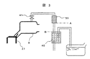
したがって、該センサをキャニスタよりも上方に設置させることで、液化燃料の滞留を防止する。前述の内容を図示すると図3のようになる。すなわちエバポ濃度センサ取り付け位置Aをキャニスタ取り付け位置Bよりも上方にとすることで、本課題を解決することができる。 Accordingly, the liquefied fuel is prevented from staying by installing the sensor above the canister. The above contents are illustrated in FIG. In other words, this problem can be solved by setting the evaporation concentration sensor attachment position A above the canister attachment position B.
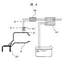
また、図4にあるように該センサ取り付け位置Aを、パージバルブの取り付け位置Cまたは、吸気管のパージ開放部位置Dより上方に設置していても、液化した蒸発燃料は該センサ部に滞留することなく、該センサへの影響が防止できる。 Further, as shown in FIG. 4, even if the sensor mounting position A is installed above the purge valve mounting position C or the intake pipe purge opening position D, the liquefied evaporated fuel stays in the sensor section. Therefore, the influence on the sensor can be prevented.
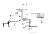
さらに、機関の構造上エバポ濃度センサが前述のキャニスタ,パージバルブおよび吸気管のパージ開放部より、下方に設置せざるを得ない時は、図5にあるように液化燃料を燃料タンクに還流させる配管(還流管)52をエバポ濃度センサの下方に設け、液化燃料によるエバポ濃度センサへの影響を防止する。 Further, when the evaporation concentration sensor must be installed below the above-described canister, purge valve and purge opening of the intake pipe due to the structure of the engine, a pipe for returning the liquefied fuel to the fuel tank as shown in FIG. A (reflux pipe) 52 is provided below the evaporation concentration sensor to prevent the liquefied fuel from affecting the evaporation concentration sensor.
また、この還流管52に遮断弁51を設置することで、機関停止中の燃料タンクで発生するエバポの流入防止および、パージ中にキャニスタ内の吸着燃料の放出を防止することができる。
Further, by installing the
以上のように、本発明の形態は、上記の構成としたことによって次の機能を奏するものである。 As described above, the embodiment of the present invention exhibits the following functions by adopting the above configuration.
すなわち、本実施の形態の内燃機関のパージ制御装置の目的とするところは、エバポ濃度センサとキャニスタおよびパージバルブ等のパージ配管の取り付け位置を最適化することで、液化した蒸発燃料による該センサの特性変化,変質および破損を防止することができる内燃機関のキャニスタパージ制御装置を提供することにある。 In other words, the purpose of the purge control device for an internal combustion engine according to the present embodiment is to optimize the attachment positions of the evaporation concentration sensor and the purge piping such as the canister and the purge valve so that the characteristics of the sensor due to the liquefied evaporated fuel can be obtained. An object of the present invention is to provide a canister purge control device for an internal combustion engine that can prevent changes, alterations and damages.
以上、本発明の一実施形態について詳説したが、本発明は前記実施形態に限定されるものでなく、特許請求の範囲に記載された発明の精神を逸脱しない範囲で、設計において種々の変更ができるものである。 Although one embodiment of the present invention has been described in detail above, the present invention is not limited to the above-described embodiment, and various changes in design can be made without departing from the spirit of the invention described in the claims. It can be done.
7…空気流量計(エアフローメータ)、8…スロットルバルブ開度検出手段(スロットルセンサ)、12…燃料を燃焼室に噴射する手段(インジェクタ)、22…排気ガスの酸素濃度を検出する手段(O2 センサ)、40…蒸発燃料貯蔵装置(キャニスタ)、41…蒸発燃料を燃焼室に放出する手段(キャニスタパージバルブ)、50…蒸発燃料のHC濃度を検出する手段(エバポ濃度センサ)。 7: Air flow meter (air flow meter), 8: Throttle valve opening detection means (throttle sensor), 12 ... Means for injecting fuel into the combustion chamber (injector), 22 ... Means for detecting oxygen concentration in exhaust gas (O 2 sensors), 40 ... evaporated fuel storage device (canister), 41 ... means for discharging the evaporated fuel to the combustion chamber (canister purge valve), 50 ... means for detecting the HC concentration of the evaporated fuel (evaporation concentration sensor).
Claims (6)
6. The canister purge apparatus for an internal combustion engine according to claim 5, wherein means for shutting off the evaporated fuel and the liquefied evaporated fuel are installed in the piping for circulating the liquefied evaporated fuel.
Priority Applications (1)
| Application Number | Priority Date | Filing Date | Title |
|---|---|---|---|
| JP2004109574A JP2005291138A (en) | 2004-04-02 | 2004-04-02 | Canister purge control device for internal combustion engine |
Applications Claiming Priority (1)
| Application Number | Priority Date | Filing Date | Title |
|---|---|---|---|
| JP2004109574A JP2005291138A (en) | 2004-04-02 | 2004-04-02 | Canister purge control device for internal combustion engine |
Publications (1)
| Publication Number | Publication Date |
|---|---|
| JP2005291138A true JP2005291138A (en) | 2005-10-20 |
Family
ID=35324345
Family Applications (1)
| Application Number | Title | Priority Date | Filing Date |
|---|---|---|---|
| JP2004109574A Pending JP2005291138A (en) | 2004-04-02 | 2004-04-02 | Canister purge control device for internal combustion engine |
Country Status (1)
| Country | Link |
|---|---|
| JP (1) | JP2005291138A (en) |
Cited By (1)
| Publication number | Priority date | Publication date | Assignee | Title |
|---|---|---|---|---|
| JP2019143564A (en) * | 2018-02-22 | 2019-08-29 | トヨタ自動車株式会社 | Evaporation fuel treatment device |
-
2004
- 2004-04-02 JP JP2004109574A patent/JP2005291138A/en active Pending
Cited By (2)
| Publication number | Priority date | Publication date | Assignee | Title |
|---|---|---|---|---|
| JP2019143564A (en) * | 2018-02-22 | 2019-08-29 | トヨタ自動車株式会社 | Evaporation fuel treatment device |
| JP7027942B2 (en) | 2018-02-22 | 2022-03-02 | トヨタ自動車株式会社 | Evaporative fuel processing equipment |
Similar Documents
| Publication | Publication Date | Title |
|---|---|---|
| JP5240059B2 (en) | Abnormality detector for exhaust gas recirculation system | |
| US6647710B2 (en) | Exhaust gas purifying apparatus for internal combustion engines | |
| JP2004211610A (en) | Fuel injection control method and device for bifuel type internal combustion engine | |
| JPH0524938U (en) | Fuel vapor emission suppression device for internal combustion engine | |
| JPH0642415A (en) | Evaporative fuel treatment system for internal combustion engine | |
| US5579747A (en) | Device for detecting abnormality of fuel supply system of internal combustion engines | |
| WO2011129267A1 (en) | Air-fuel ratio learning control device for bifuel engine | |
| JP2005291138A (en) | Canister purge control device for internal combustion engine | |
| JPH06167236A (en) | Trouble detecting device for pressure sensor | |
| JP2019049219A (en) | Engine system | |
| JP6906856B2 (en) | Internal combustion engine control device | |
| JP3263768B2 (en) | Fuel supply system for gaseous fuel engine | |
| JP2007239476A (en) | Bi-fuel engine fuel selection control device | |
| JP4678336B2 (en) | Diagnostic apparatus and diagnostic method for air-fuel ratio sensor | |
| US9528460B2 (en) | Fuel injection apparatus | |
| JP2007008386A (en) | Fuel remaining amount calculation device for vehicle | |
| JP7472764B2 (en) | Engine equipment | |
| JP7149883B2 (en) | Canister purge controller | |
| JP5410365B2 (en) | Evaporation feeder | |
| JP3065176B2 (en) | Engine air-fuel ratio control device | |
| JP7040108B2 (en) | Evaporative fuel processing equipment | |
| JP2000274317A (en) | Evaporative fuel processing device and failure diagnosis device for internal combustion engine | |
| JP2005233147A (en) | Control device for variable cylinder internal combustion engine | |
| JPH06193518A (en) | Failure diagnostic device for evaporation fuel supplying device | |
| JP2004316547A (en) | Evaporative fuel treatment system for internal combustion engine |
Legal Events
| Date | Code | Title | Description |
|---|---|---|---|
| RD04 | Notification of resignation of power of attorney |
Free format text: JAPANESE INTERMEDIATE CODE: A7424 Effective date: 20060424 |
|
| A621 | Written request for application examination |
Free format text: JAPANESE INTERMEDIATE CODE: A621 Effective date: 20060726 |
|
| A131 | Notification of reasons for refusal |
Free format text: JAPANESE INTERMEDIATE CODE: A131 Effective date: 20090106 |
|
| A02 | Decision of refusal |
Free format text: JAPANESE INTERMEDIATE CODE: A02 Effective date: 20090602 |