JP2005291055A - Engine provided with exhaust gas recirculation system with diagnosic system - Google Patents
Engine provided with exhaust gas recirculation system with diagnosic system Download PDFInfo
- Publication number
- JP2005291055A JP2005291055A JP2004105824A JP2004105824A JP2005291055A JP 2005291055 A JP2005291055 A JP 2005291055A JP 2004105824 A JP2004105824 A JP 2004105824A JP 2004105824 A JP2004105824 A JP 2004105824A JP 2005291055 A JP2005291055 A JP 2005291055A
- Authority
- JP
- Japan
- Prior art keywords
- egr
- gas temperature
- temperature
- failure
- egr gas
- Prior art date
- Legal status (The legal status is an assumption and is not a legal conclusion. Google has not performed a legal analysis and makes no representation as to the accuracy of the status listed.)
- Pending
Links
- 238000003745 diagnosis Methods 0.000 claims description 37
- 238000001514 detection method Methods 0.000 description 28
- 238000011144 upstream manufacturing Methods 0.000 description 12
- 230000007423 decrease Effects 0.000 description 5
- 238000010586 diagram Methods 0.000 description 5
- 238000001816 cooling Methods 0.000 description 4
- 238000000034 method Methods 0.000 description 4
- 238000009434 installation Methods 0.000 description 3
- 230000000295 complement effect Effects 0.000 description 1
- 230000007257 malfunction Effects 0.000 description 1
Images
Classifications
-
- Y—GENERAL TAGGING OF NEW TECHNOLOGICAL DEVELOPMENTS; GENERAL TAGGING OF CROSS-SECTIONAL TECHNOLOGIES SPANNING OVER SEVERAL SECTIONS OF THE IPC; TECHNICAL SUBJECTS COVERED BY FORMER USPC CROSS-REFERENCE ART COLLECTIONS [XRACs] AND DIGESTS
- Y02—TECHNOLOGIES OR APPLICATIONS FOR MITIGATION OR ADAPTATION AGAINST CLIMATE CHANGE
- Y02T—CLIMATE CHANGE MITIGATION TECHNOLOGIES RELATED TO TRANSPORTATION
- Y02T10/00—Road transport of goods or passengers
- Y02T10/10—Internal combustion engine [ICE] based vehicles
- Y02T10/12—Improving ICE efficiencies
Landscapes
- Exhaust-Gas Circulating Devices (AREA)
- Combined Controls Of Internal Combustion Engines (AREA)
Abstract
Description
本発明は、車両用、産業用等のEGR(排気ガス再循環)システムを備えたエンジンに適用され、EGRガス温度の検出値を用いてEGRシステムの故障の有無を診断するEGR故障診断装置付きEGRシステムを備えたエンジンに関する。 The present invention is applied to an engine equipped with an EGR (exhaust gas recirculation) system for vehicles, industrial use, etc., and has an EGR failure diagnosis device for diagnosing the presence or absence of a failure of the EGR system using a detected value of the EGR gas temperature. The present invention relates to an engine equipped with an EGR system.
エンジンの排気ガスの一部で構成されるEGRガスを、EGR弁によって開閉されるEGR通路を通して吸気通路に還流するEGR(排気ガス再循環)システムを備えたエンジンにおいては、前記EGR弁の作動不良や破損等のEGRシステムにおける故障の発生を検知して、迅速な対処を行うための手段として、例えば特許文献1(特開2000−34954号公報)に開示されているように、EGR通路におけるEGR弁下流側(吸気通路側)のEGRガス温度を検出して、該EGRガス温度の検出値がEGRシステムにおける故障判定条件にあるか否かで、EGRシステムの故障の有無を判断する技術が提案されている。 In an engine equipped with an EGR (exhaust gas recirculation) system that recirculates EGR gas, which is part of the exhaust gas of the engine, to the intake passage through the EGR passage opened and closed by the EGR valve, the EGR valve malfunctions. As a means for detecting the occurrence of a failure in the EGR system such as damage or damage and taking a quick response, for example, as disclosed in Patent Document 1 (Japanese Patent Laid-Open No. 2000-34954), EGR in the EGR passage A technique is proposed in which the EGR gas temperature on the downstream side of the valve (intake passage side) is detected, and whether or not there is a failure in the EGR system is determined by whether or not the detected value of the EGR gas temperature is in a failure determination condition in the EGR system. Has been.
前記特許文献1の技術においては、EGR通路のEGR弁の下流側(吸気通路側)にEGRガス温度を検出するEGRガス温度センサを設置し、該EGRガス温度センサからのEGRガス温度の検出値をEGR故障診断を行うコントローラに入力し、該コントローラにおいて予めEGR弁の故障判定の基準値としてEGR弁開時の最低温度を設定し、EGR弁の開弁信号が出されている時に、EGRガス温度の検出値が前記最低温度よりも低い状態が一定時間以上続いたら、EGR弁が閉弁状態でスティックしているものと判断するように構成されている。
In the technique of
前記特許文献1の技術にあっては、EGRガス温度を検出するEGRガス温度センサは、EGR通路のEGR弁の下流側(吸気通路側)に設置してはいるが、設置場所は特定されていないため、EGR弁に近い位置等、設置場所によってはEGR弁の閉弁時におけるEGRガス温度の低下あるいはEGR弁の開弁時におけるEGRガス温度の上昇の検出量が小さくなって、かかる小さな温度検出量では、EGR弁の挙動を正確に検知することによりEGRシステムの故障を正確かつ迅速に検知するのが困難となる。
In the technique of
また、かかる従来技術にあっては、EGR弁の開弁信号が出されている時に、EGRガス温度の検出値が、予め設定されたEGR弁開時の前記最低温度よりも低い状態が一定時間以上続いたときEGR弁に故障を判断しているにとどまり、つまりEGR弁の開弁時においてEGR弁の故障診断をしているにとどまり、EGR弁が閉弁した後におけるEGRガス温度の変化を用いてEGR弁を含むEGRシステムの故障診断を行うようになってはいない。 Further, in this prior art, when the EGR valve opening signal is output, the EGR gas temperature detection value is lower than the preset minimum temperature when the EGR valve is open for a certain period of time. When the EGR valve continues, only the failure of the EGR valve is judged. That is, the EGR valve failure diagnosis is performed only when the EGR valve is opened, and the change in the EGR gas temperature after the EGR valve is closed. It is not used to perform fault diagnosis of an EGR system including an EGR valve.
従って、本発明はかかる従来技術の課題に鑑み、EGR弁の閉弁時及び開弁時の双方においてEGR弁を含むEGRシステムの挙動に正確に連動して高精度で以ってEGRガス温度を検出可能として、EGRシステムの故障を正確かつ迅速に検知し得るEGRシステムを備えたエンジンを提供することを目的とする。 Therefore, in view of the problems of the prior art, the present invention accurately adjusts the EGR gas temperature in conjunction with the behavior of the EGR system including the EGR valve both when the EGR valve is closed and when the EGR valve is opened. An object of the present invention is to provide an engine equipped with an EGR system that can detect a failure of the EGR system accurately and quickly.
本発明はかかる目的を達成するもので、エンジンの排気ガスの一部で構成されるEGRガスを、EGR弁によって開閉されるEGR通路を通して吸気通路に還流するEGR(排気ガス再循環)システムを備えたエンジンにおいて、前記EGR通路の前記吸気通路との合流部の近傍に、前記EGRガスの温度を検出するEGRガス温度センサを設けるとともに、該EGRガス温度センサから入力されるEGRガス温度の検出値に基づき前記EGR弁を含むEGRシステムの故障の有無を診断するEGR故障診断装置を備えたことを特徴とする。 The present invention achieves such an object, and includes an EGR (exhaust gas recirculation) system that recirculates EGR gas constituted by a part of engine exhaust gas to an intake passage through an EGR passage opened and closed by an EGR valve. In the engine, an EGR gas temperature sensor for detecting the temperature of the EGR gas is provided in the vicinity of the joining portion of the EGR passage with the intake passage, and a detected value of the EGR gas temperature input from the EGR gas temperature sensor. And an EGR failure diagnosis device for diagnosing whether or not there is a failure in the EGR system including the EGR valve.
EGRシステムを備えたエンジンにおいて、EGRシステムの故障、特にEGR弁の故障を正確に検知する手段としては、前記特許文献1のように、EGR通路におけるEGRガス温度の変化を検出する手段が多く用いられているが、EGRシステムの故障を迅速かつ正確に検知するには、かかる手段のみでは十分ではない。
In an engine equipped with an EGR system, as a means for accurately detecting a failure of an EGR system, in particular, a failure of an EGR valve, a means for detecting a change in the EGR gas temperature in the EGR passage as in the above-mentioned
そこでかかる発明においては、EGRガスの温度を検出するEGRガス温度センサを、EGR通路の吸気通路との合流部の近傍に設置して、かかる課題を解決している。
即ち、EGR弁の閉弁により、EGR通路における該EGR弁の下流側つまり該EGR弁とEGR通路の吸気通路への合流部との間におけるEGRガスの温度が低下する過程で、前記合流部近傍のEGR通路内におけるEGRガスが吸気通路を流れる低温の吸気によって冷却されることにより、該合流部近傍のEGR通路の温度低下量及び温度低下速度が、前記合流部近傍よりもEGR弁寄りの部位における温度低下量及び温度低下速度よりも大きくなる。
Therefore, in such an invention, an EGR gas temperature sensor for detecting the temperature of the EGR gas is installed in the vicinity of the joining portion of the EGR passage and the intake passage to solve such a problem.
That is, when the EGR valve is closed, the EGR gas temperature decreases in the EGR passage on the downstream side of the EGR valve, that is, between the EGR valve and the merging portion of the EGR passage to the intake passage. When the EGR gas in the EGR passage is cooled by the low-temperature intake air flowing through the intake passage, the temperature reduction amount and the temperature reduction speed of the EGR passage in the vicinity of the merging portion are closer to the EGR valve than in the vicinity of the merging portion. The temperature drop amount and the temperature drop speed at
従ってかかる発明によれば、前記のように、吸気の冷却によって、EGR通路の温度低下量及び温度低下速度がEGR弁寄りの部位よりも大きくなる吸気通路との合流部近傍のEGR通路にEGRガス温度センサを設置したので、EGR弁を含むEGRシステムの故障によるEGRガス温度の変化の検出精度及び検出速度を上げることが可能となり、EGR故障診断装置において、前記のように検出精度の高いEGRガス温度センサからのEGRガス温度の検出値を用いて、EGR弁を含むEGRシステムの故障の有無を診断することにより、EGRシステムの故障を正確かつ迅速に検知することができる。
さらに、かかる発明によれば、EGR弁の開弁時においても、EGRガス温度の検出値を用いて、該EGRガス温度の検出値が予め設定されたEGRガス温度の目標値よりも低くなっているとき前記EGRシステムの故障を判定することもできる。
よってかかる発明によれば、EGR弁の閉弁時及び開弁時の双方において、EGRシステムの故障を正確かつ迅速に検知することが可能となる。
Therefore, according to this invention, as described above, the EGR gas is introduced into the EGR passage near the junction with the intake passage where the temperature reduction rate and the temperature reduction speed of the EGR passage are larger than those near the EGR valve due to the cooling of the intake air. Since the temperature sensor is installed, it is possible to increase the detection accuracy and the detection speed of the change in the EGR gas temperature due to the failure of the EGR system including the EGR valve, and the EGR gas having high detection accuracy as described above in the EGR failure diagnosis device. By using the detected value of the EGR gas temperature from the temperature sensor to diagnose the presence or absence of a failure in the EGR system including the EGR valve, the failure in the EGR system can be detected accurately and quickly.
Furthermore, according to this invention, even when the EGR valve is opened, the detected value of the EGR gas temperature is lower than the preset target value of the EGR gas temperature using the detected value of the EGR gas temperature. It is also possible to determine whether the EGR system is faulty.
Therefore, according to this invention, it is possible to accurately and quickly detect a failure of the EGR system both when the EGR valve is closed and when the valve is opened.
かかる発明において好ましくは、前記EGR故障診断装置は、前記EGR弁の閉弁時にはEGRガス温度の検出値が予め設定されたEGRガス温度の目標値よりも高くなっているとき、あるいは前記EGR弁の開弁時にはEGRガス温度の検出値が予め設定されたEGRガス温度の目標値よりも低くなっているとき、前記EGRシステムの故障を判定するように構成されてなる。
このように構成すれば、EGR故障診断装置において、EGRシステムの故障時におけるEGRガス温度の基準値(目標値)を予め設定しておき、常時、前記のように高い検出精度及び検出速度で検出されたEGRガス温度検出値と前記EGRガス温度の基準値とを比較してEGRシステムの故障判定を行うので、EGRシステムの故障を正確に検知することができる。
In this invention, preferably, the EGR failure diagnosis device is configured such that when the EGR valve is closed, the detected value of the EGR gas temperature is higher than a preset target value of the EGR gas temperature, or the EGR valve When the valve is opened, when the detected value of the EGR gas temperature is lower than a preset target value of the EGR gas temperature, a failure of the EGR system is determined.
With this configuration, in the EGR failure diagnosis apparatus, a reference value (target value) of the EGR gas temperature at the time of failure of the EGR system is set in advance, and detection is always performed with high detection accuracy and detection speed as described above. Since the EGR system failure determination is performed by comparing the detected EGR gas temperature detection value and the reference value of the EGR gas temperature, the failure of the EGR system can be accurately detected.
また、かかる発明において好ましくは、前記EGR故障診断装置は、前記EGR弁の閉弁時にはEGRガス温度の単位時間当たり温度降下の検出値が予め設定された単位時間当たり温度降下の目標値よりも小さくなっているとき、あるいは前記EGR弁の開弁時にはEGRガス温度の単位時間当たり温度上昇の検出値が予め設定された単位時間当たり温度上昇の目標値よりも小さくなっているとき、前記EGRシステムの故障を判定するように構成されてなる。
このように構成すれば、EGR故障診断装置において、EGRシステムの故障時におけるEGRガス温度の単位時間当たり温度降下あるいは温度上昇の基準値(目標値)を予め設定しておき、常時、前記のように高い検出精度及び検出速度で検出されたEGRガス温度検出値に基づき算出した温度降下あるいは温度上昇の算出値とを比較してEGRシステムの故障判定を行うので、EGRシステムの故障によるEGRガス温度の変化を随時検知することが可能となって、EGRシステムの故障を、より早期にかつ高精度で検知できる。
In the invention, preferably, the EGR failure diagnosis device is configured such that when the EGR valve is closed, the detected value of the temperature drop per unit time of the EGR gas temperature is smaller than a preset target value of the temperature drop per unit time. Or when the EGR valve is opened, if the detected value of the temperature increase per unit time of the EGR gas temperature is smaller than a preset target value of the temperature increase per unit time, the EGR system It is configured to determine a failure.
With this configuration, in the EGR failure diagnosis apparatus, a reference value (target value) for temperature drop or temperature rise of the EGR gas temperature per unit time at the time of failure of the EGR system is set in advance, and is always as described above. Since the EGR system failure determination is performed by comparing the calculated value of temperature drop or temperature rise calculated based on the detected EGR gas temperature value detected with high detection accuracy and detection speed, the EGR gas temperature due to the failure of the EGR system It is possible to detect changes in the EGR system at any time, so that a failure of the EGR system can be detected earlier and with high accuracy.
また、かかる発明において好ましくは、前記EGRガス温度センサを、前記合流部の近傍における吸気流下流側の部位に設ける。
このように構成すれば、吸気の冷却によってEGR通路の温度低下量及び温度低下速度が最も大きくなる、EGR通路の吸気通路との合流部の吸気流下流側の部位にEGRガス温度センサを設置したので、EGRシステムの故障によるEGRガス温度の変化の検出精度及び検出速度を、より上げることができる。
In the present invention, preferably, the EGR gas temperature sensor is provided at a portion on the downstream side of the intake air flow in the vicinity of the merging portion.
If comprised in this way, the EGR gas temperature sensor was installed in the site | part of the inlet flow downstream of the confluence | merging part with the intake passage of an EGR passage where the temperature fall amount and temperature fall speed of an EGR passage become the largest by cooling of intake air Therefore, the detection accuracy and the detection speed of the change in the EGR gas temperature due to the failure of the EGR system can be further increased.
また、かかる発明において好ましくは、前記EGRガス温度センサを、前記合流部の近傍における吸気流下流側の部位を含む2箇所に設ける。
このように構成すれば、一方側のEGRガス温度センサが故障した場合でも、前記合流部の近傍に設置した他のEGRガス温度センサで、故障したEGRガス温度センサと同程度の検出精度及び検出速度で以ってEGRシステムの故障検知を補完できる。
In the present invention, preferably, the EGR gas temperature sensors are provided at two locations including a portion on the downstream side of the intake air flow in the vicinity of the merging portion.
With this configuration, even when the EGR gas temperature sensor on one side fails, the other EGR gas temperature sensors installed in the vicinity of the merging section can detect and detect the same degree of accuracy and detection as the failed EGR gas temperature sensor. The speed can complement the EGR system failure detection.
また、かかる発明において好ましくは、前記EGR故障診断装置に、該EGR故障診断装置における前記EGRシステムの故障判定結果を表示する表示装置を接続する。
このように構成すれば、EGR故障診断装置の判定によるEGRシステムの故障の有無を、時々刻々表示装置に表示することにより、作業者は迅速にEGRシステムの故障を検知して対策を行うことができる。
In the invention, preferably, a display device that displays a failure determination result of the EGR system in the EGR failure diagnosis device is connected to the EGR failure diagnosis device.
With this configuration, the operator can quickly detect a failure in the EGR system and take countermeasures by displaying the presence or absence of the failure in the EGR system as determined by the EGR failure diagnosis device on a display device. it can.
本発明によれば、吸気の冷却によって、EGR通路の温度低下量及び温度低下速度がEGR弁寄りの部位よりも大きくなる吸気通路との合流部近傍のEGR通路にEGRガス温度センサを設置したので、EGRシステムの故障によるEGRガス温度の変化の検出精度及び検出速度を上げることが可能となり、かかるEGRガス温度センサからのEGRガス温度の検出値を用いて、EGRシステムの故障の有無を診断することにより、EGRシステムの故障を迅速かつ正確に検知することができる。
さらに、本発明によれば、EGR弁の開弁時においても、EGRガス温度の検出値を用いて、該EGRガス温度の検出値が予め設定されたEGRガス温度の目標値よりも低くなっているとき、前記EGRシステムの故障を判定することもできる。
よって本発明によれば、EGR弁の閉弁時及び開弁時の双方において、EGRシステムの故障を迅速かつ正確に検知することが可能となる。
According to the present invention, the EGR gas temperature sensor is installed in the EGR passage in the vicinity of the merged portion with the intake passage where the temperature reduction amount and the temperature reduction speed of the EGR passage are larger than the portion near the EGR valve due to the cooling of the intake air. It becomes possible to increase the detection accuracy and the detection speed of the change in the EGR gas temperature due to the failure of the EGR system, and the presence or absence of the failure of the EGR system is diagnosed using the detected value of the EGR gas temperature from the EGR gas temperature sensor. As a result, a failure of the EGR system can be detected quickly and accurately.
Furthermore, according to the present invention, even when the EGR valve is opened, the detected value of the EGR gas temperature is lower than the preset target value of the EGR gas temperature using the detected value of the EGR gas temperature. It is also possible to determine a failure of the EGR system.
Therefore, according to the present invention, it is possible to quickly and accurately detect a failure of the EGR system both when the EGR valve is closed and when the valve is opened.
以下、本発明を図に示した実施例を用いて詳細に説明する。但し、この実施例に記載されている構成部品の寸法、材質、形状、その相対配置などは特に特定的な記載がない限り、この発明の範囲をそれのみに限定する趣旨ではなく、単なる説明例にすぎない。
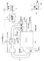
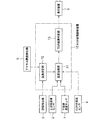
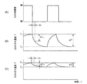
図1は本発明の実施例に係る故障診断装置付きEGRシステムを備えたエンジンの全体構成図、図2は制御ブロック図、図3はEGRシステムの故障診断作用説明用の線図である。
Hereinafter, the present invention will be described in detail with reference to the embodiments shown in the drawings. However, the dimensions, materials, shapes, relative arrangements, and the like of the component parts described in this example are not intended to limit the scope of the present invention only to specific examples unless otherwise specified. Only.
FIG. 1 is an overall configuration diagram of an engine including an EGR system with a failure diagnosis device according to an embodiment of the present invention, FIG. 2 is a control block diagram, and FIG. 3 is a diagram for explaining a failure diagnosis operation of the EGR system.
実施例を示す図1(A)において、100はエンジン、105は該エンジン100の吸気通路、104は排気通路である。102は前記排気通路104の途中から分岐されて前記吸気通路105に接続されるEGR通路で、前記排気通路104を通流する排気ガスの一部で構成されるEGRガスを前記吸気通路105へ還流する。106は該EGR通路102の前記吸気通路105への合流部を示す。
前記EGR通路102には、上流側(排気通路104側)から順に、該EGR通路102に導入された前記EGRガスを冷却するEGRクーラ103及び該EGR通路102を開閉するEGR弁101が配設されている。前記EGR弁101は、前記EGRガスの流量を調整する機能も備えている。
In FIG. 1A showing the embodiment, 100 is an engine, 105 is an intake passage of the
In the EGR
1は前記EGR通路102に設置された下流側温度センサで、前記EGR通路102の吸気通路105との合流部106の近傍つまり該合流部106の直上流部位に設置されてEGRガスの温度を検出するものである。該下流側温度センサ1は、図1(B)に示すように、前記合流部106の近傍における吸気流(矢印)の下流側の部位に設置されている。
2は前記EGR通路102に設置された上流側温度センサで、前記EGR通路102の吸気通路105との合流部106の近傍に設置されてEGRガスの温度を検出するものである。該上流側温度センサ2は、図1(B)に示すように、前記合流部106の近傍における前記下流側温度センサ1と同一断面位置に、該下流側温度センサ1に対して円周方向に所定角度(この例では90°)ずらして設けられている。尚、該上流側温度センサ2は必要に応じて省略することもできる。
3は前記エンジン100の回転数(エンジン回転数)を検出する回転検出器、4は前記EGR弁101の開閉タイミング(EGR弁101の開弁、閉弁の時間変化)を検出するEGR弁開度センサである。また、6はアクセル開度検出器である。
3 is a rotation detector for detecting the rotation speed of the engine 100 (engine rotation speed), and 4 is an EGR valve opening degree for detecting the opening / closing timing of the EGR valve 101 (time change of opening and closing of the EGR valve 101). It is a sensor.
10はEGR故障診断装置で、前記下流側温度センサ1及び上流側温度センサ2からEGRガス温度の検出値が入力されるとともに、前記EGR弁開度センサ4からEGR弁101の開閉タイミングの検出値が入力され、また前記回転検出器3からエンジン回転数の検出値が入力され、さらに前記アクセル開度検出器6からアクセル開度の検出値が入力され、前記EGRガス温度、EGR弁101の開閉タイミング、及びエンジン回転数等の検出値に基づき、後述するような演算、制御を行って、前記EGR弁101を含むEGRシステムの故障の有無を診断するものである。5は該EGR故障診断装置10に接続された表示装置で、該EGR故障診断装置10におけるEGRシステムの故障判定結果を表示するものである。
次に、図2に基づきかかる故障診断装置付きEGRシステムを備えたエンジンの動作を説明する。前記下流側温度センサ1及び上流側温度センサ2からのEGRガス温度の検出値、並びに前記EGR弁開度センサ4からのEGR弁101の開閉タイミングの検出値は前記EGR故障診断装置10の温度比較部11に入力される。また、前記回転検出器3からのエンジン回転数の検出値及びアクセル開度検出器6からのアクセル開度の検出値は前記EGR故障診断装置10の温度設定部12に入力される。
Next, the operation of the engine equipped with such an EGR system with a failure diagnosis device will be described with reference to FIG. The detected value of the EGR gas temperature from the
ここで、図3の(A)は前記EGR弁101の開弁、閉弁の時間変化を示している。また、図3の(B)及び(C)は、前記EGR弁101の開弁、閉弁に伴う下流側温度センサ1設置部近傍と前記EGR弁101の直下流部位とのEGRガス温度の時間変化の比較を示している。
前記温度設定部12においては、EGR弁101の閉弁後(図3の(A))において、EGRシステムが故障していると判断されるEGRガス温度の温度T1からΔT低下後の温度T2(図3の(B))の基準値(目標値)T20、つまりEGR弁101の閉弁後にEGRガス温度Tが該基準値T20以下の温度に低下しないとき、EGRシステムが故障していると判断される温度(T20)が、エンジン回転数に対応して設定されている。
また、前記温度設定部12においては、EGR弁101の閉弁後(図3の(A))において、EGRシステムが故障していると判断されるEGRガス温度の単位時間当たり温度降下ΔT/Δtの目標値ΔT1/Δt(図3の(B))の基準値(目標値)ΔT10/Δt、つまりEGR弁101の閉弁後にEGRガス温度の単位時間当たり温度降下ΔT/Δtが該基準値ΔT10/Δtよりも小さいときEGRシステムが故障していると判断される単位時間当たり温度降下が、エンジン回転数およびアクセル開度に対応して設定されている。
Here, (A) of FIG. 3 shows the time change of the opening and closing of the
In the
Further, in the
さらに、前記温度設定部12においては、前記EGR弁101の開弁後において、EGRシステムが故障していると判断されるEGRガス温度の温度T2からΔT上昇後の温度T1(図3の(B)参照)の基準値(目標値)T10、つまりEGR弁101の開弁後にEGRガス温度Tが該基準値T10以上の温度に上昇しないとき、EGRシステムが故障していると判断される温度(T10)が、エンジン回転数及びアクセル開度に対応して設定されている。
また図示を省略したが、前記温度設定部12においては、EGR弁101の開弁後において、EGRシステムが故障していると判断されるEGRガス温度の単位時間当たり温度上昇の基準値(目標値)、つまりEGR弁101の開弁後にEGRガス温度の単位時間当たり温度上昇が該基準値よりも小さいとき、EGRシステムが故障していると判断される単位時間当たり温度上昇が、エンジン回転数及びアクセル開度に対応して設定されている。
Further, in the
Although not shown, in the
そして前記温度比較部11においては、前記EGR弁開度センサ4からのEGR弁101の閉弁信号発信後の、前記下流側温度センサ1からのEGRガス温度の検出値における温度降下ΔT後の最低温度T2と前記温度設定部12に設定されている最低温度T2の基準値(目標値)T20とを比較し、その比較結果をEGR故障判定部13に入力する。(図2参照)
EGR故障判定部13においては、前記EGRガス温度の検出値による最低温度T2が前記基準値(目標値)T20よりも高くなっているとき(T2>T20)、EGR弁101を含むEGRシステムに故障が発生しているものと判定して、その判定結果を前記表示装置5に出力する。該表示装置5は、前記EGR故障診断装置10におけるEGRシステムの故障判定結果を表示する。
尚、前記EGRガス温度の検出値による最低温度T2が前記基準値(目標値)T20よりも低下しているとき(T2≦T20)、前記EGRシステムは故障を発生することなく順調に運転されているものと判定する。
In the temperature comparison unit 11, the lowest value after the temperature drop ΔT in the detected value of the EGR gas temperature from the
The EGR
Note that when the minimum temperature T 2 based on the detected value of the EGR gas temperature is lower than the reference value (target value) T 20 (T 2 ≦ T 20 ), the EGR system performs smoothly without causing a failure. It is determined that the vehicle is being driven.
また、次の3つの動作により、EGRシステムの故障発生の有無の判定を行うこともできる。
(その第1)
前記温度比較部11においては、前記EGR弁101の閉弁信号発信後の、前記下流側温度センサ1からのEGRガス温度の検出値により算出したEGRガス温度の単位時間当たり温度降下ΔT/Δtと温度設定部12に設定されている温度降下ΔT/Δtの目標値ΔT1/Δtとを比較し、その比較結果をEGR故障判定部13に入力する。
EGR故障判定部13においては、前記EGRガス温度の温度降下の検出値ΔT/Δtが前記基準値(目標値)ΔT1/Δtよりも小さくなっているとき(ΔT1/Δt>ΔT/Δt)、EGR弁101を含むEGRシステムに故障が発生しているものと判定して、その判定結果を前記表示装置5に出力する。
尚、前記温度降下の検出値ΔT/Δtが前記基準値(目標値)ΔT1/Δtよりも大きくなっているとき(ΔT1/Δt≦ΔT/Δt)、前記EGRシステムは故障を発生することなく順調に運転されているものと判定する。
Further, it is possible to determine whether or not a failure has occurred in the EGR system by the following three operations.
(Part 1)
In the temperature comparison unit 11, the temperature drop ΔT / Δt per unit time of the EGR gas temperature calculated based on the detected value of the EGR gas temperature from the
In EGR
When the detected value ΔT / Δt of the temperature drop is larger than the reference value (target value) ΔT 1 / Δt (ΔT 1 / Δt ≦ ΔT / Δt), the EGR system will fail. It is determined that the vehicle is operating smoothly.
(その第2)
前記温度比較部11においては、前記EGR弁101の開弁信号発信後の、前記下流側温度センサ1からのEGRガス温度の検出値における温度上昇ΔT後の最高温度T1と前記温度設定部12に設定されている最高温度T1の基準値(目標値)T10とを比較し、その比較結果をEGR故障判定部13に入力する。
EGR故障判定部13においては、前記EGRガス温度の検出値による最高温度T1が前記基準値(目標値)T10よりも低くなっているとき(T10>T1)、EGR弁101を含むEGRシステムに故障が発生しているものと判定して、その判定結果を前記表示装置5に出力する。該表示装置5は、前記EGR故障診断装置10におけるEGRシステムの故障判定結果を表示する。
尚、前記EGRガス温度の検出値による最高温度T1が前記基準値(目標値)T10よりも上昇しているとき(T20≦T2)、前記EGRシステムは故障を発生することなく順調に運転されているものと判定する。
(Part 2)
In the temperature comparison unit 11, the maximum temperature T 1 after the temperature increase ΔT in the detected value of the EGR gas temperature from the
The EGR
Note that when the maximum temperature T 1 based on the detected value of the EGR gas temperature is higher than the reference value (target value) T 10 (T 20 ≦ T 2 ), the EGR system performs smoothly without causing a failure. It is determined that the vehicle is being driven.
(その第3)
前記温度比較部11においては、前記EGR弁101の開弁信号発信後の、前記下流側温度センサ1からのEGRガス温度の検出値により算出したEGRガス温度の単位時間当たり温度上昇ΔT/Δtと温度設定部12に設定されている温度上昇ΔT/Δtの目標値ΔT1/Δtとを比較し、その比較結果をEGR故障判定部13に入力する。
EGR故障判定部13においては、前記EGRガス温度の温度上昇の検出値ΔT/Δtが前記基準値(目標値)ΔT1/Δtよりも小さくなっているとき(ΔT1/Δt>ΔT/Δt)、EGR弁101を含むEGRシステムに故障が発生しているものと判定して、その判定結果を前記表示装置5に出力する。
尚、前記温度降下の検出値ΔT/Δtが前記基準値(目標値)ΔT1/Δtよりも大きくなっているとき(ΔT1/Δt≦ΔT/Δt)、前記EGRシステムは故障を発生することなく順調に運転されているものと判定する。
以上のような、EGR故障診断装置10による演算、制御により、EGR弁101を含むEGRシステムの故障を正確に検知することができる。
(Part 3)
In the temperature comparison unit 11, the temperature increase ΔT / Δt per unit time of the EGR gas temperature calculated from the detected value of the EGR gas temperature from the
In EGR
When the detected value ΔT / Δt of the temperature drop is larger than the reference value (target value) ΔT 1 / Δt (ΔT 1 / Δt ≦ ΔT / Δt), the EGR system will fail. It is determined that the vehicle is operating smoothly.
By the calculation and control by the EGR
かかる実施例によれば、図3(B)及び(C)のように、前記EGR弁101の閉弁により、EGR通路102における該EGR弁101の下流側、つまり該EGR弁101とEGR通路101の吸気通路105への合流部との間におけるEGRガスの温度が低下する過程で、前記合流部106近傍のEGR通路102内におけるEGRガスが吸気通路105を流れる低温の吸気によって冷却されることにより、図3(B)に示される該合流部106近傍のEGR通路102の温度低下量ΔT1及び温度低下速度ΔT1/Δtが、図3(C)に示されるEGR弁101の直下流部位(前記合流部106近傍よりもEGR弁寄りの部位)における温度低下量ΔT2及び温度低下速度ΔT2/Δtよりも大きくなる。
According to such an embodiment, as shown in FIGS. 3B and 3C, the
従ってかかる実施例によれば、前記のように、吸気の冷却によって、EGR通路102の温度低下量及び温度低下速度がEGR弁101寄りの部位よりも大きくなる吸気通路との合流部106近傍のEGR通路102に下流側温度センサ1を設置したので、EGR弁101を含むEGRシステムの故障によるEGRガス温度の変化の検出精度及び検出速度を上げることが可能となり、EGR故障診断装置10において、かかる下流側温度センサ1からのEGRガス温度の検出値を用いて、EGR弁101を含むEGRシステムの故障の有無を診断することにより、EGRシステムの故障を迅速かつ正確に検知することができる。
Therefore, according to this embodiment, as described above, due to the cooling of the intake air, the temperature reduction amount and the temperature reduction speed of the
さらに、かかる実施例によれば、前記のように、EGR弁101の開弁時においても、下流側温度センサ1の検出値を用いて(あるいは必要に応じて上流側温度センサ2の検出値を用いて)、該EGRガス温度の検出値が予め設定されたEGRガス温度の目標値よりも低くなっているとき、前記EGRシステムの故障を判定することもできる。
従ってかかる実施例によれば、EGR弁101の閉弁時及び開弁時の双方において、EGRシステムの故障を迅速かつ正確に検知することが可能となる。
Furthermore, according to this embodiment, as described above, even when the
Therefore, according to this embodiment, it is possible to quickly and accurately detect a failure of the EGR system both when the
また、EGRシステムの故障時におけるEGRガス温度の単位時間当たり温度降下あるいは温度上昇値ΔT/Δtの基準値(目標値)ΔT1/Δtを予め設定しておき、常時、下流側温度センサ1(あるいは上流側温度センサ2)により高い検出精度及び検出速度で検出されたEGRガス温度検出値に基づき算出した温度降下あるいは温度上昇の算出値ΔT/Δtとを比較してEGRシステムの故障判定を行うので、EGRシステムの故障によるEGRガス温度の変化を随時検知することが可能となって、EGRシステムの故障をより早期に検知できかつ高精度で検知できる。 Further, a reference value (target value) ΔT 1 / Δt of a temperature drop per unit time of the EGR gas temperature or a temperature rise value ΔT / Δt at the time of failure of the EGR system is set in advance, and the downstream side temperature sensor 1 ( Alternatively, the failure determination of the EGR system is performed by comparing the temperature drop or temperature rise calculated value ΔT / Δt calculated based on the detected EGR gas temperature value with high detection accuracy and detection speed by the upstream temperature sensor 2). Therefore, it is possible to detect a change in the EGR gas temperature due to the failure of the EGR system at any time, so that the failure of the EGR system can be detected earlier and with high accuracy.
また、かかる実施例によれば、EGRガス温度センサを、前記合流部106の近傍の2箇所に、下流側温度センサ1、上流側温度センサ2を設けているので、一方側のEGRガス温度センサ(下流側温度センサ1)が故障した場合でも、前記合流部106の近傍に設置した他のEGRガス温度センサ上流側温度センサ2で、故障したEGRガス温度センサ(下流側温度センサ1)と同程度の検出精度及び検出速度で以ってEGRシステムの故障検知を補完できる。
Further, according to this embodiment, since the EGR gas temperature sensor is provided with the
本発明によれば、EGR弁の閉弁時及び開弁時の双方においてEGR弁を含むEGRシステムの挙動に正確に連動し、高精度で以ってEGRガス温度を検出可能として、EGRシステムの故障を正確かつ迅速に検知し得るEGRシステムを備えたエンジンを提供できる。 According to the present invention, the EGR gas temperature can be detected with high accuracy by accurately interlocking with the behavior of the EGR system including the EGR valve both when the EGR valve is closed and when the EGR valve is opened. An engine equipped with an EGR system that can detect a failure accurately and quickly can be provided.
1 下流側温度センサ
2 上流側温度センサ
3 回転検出器
4 EGR弁開度センサ
5 表示装置
6 アクセル開度検出器
10 EGR故障診断装置
100 エンジン
101 EGR弁
102 EGR通路
103 EGRクーラ
104 排気通路
105 吸気通路
106 合流部
DESCRIPTION OF
Claims (6)
Priority Applications (1)
| Application Number | Priority Date | Filing Date | Title |
|---|---|---|---|
| JP2004105824A JP2005291055A (en) | 2004-03-31 | 2004-03-31 | Engine provided with exhaust gas recirculation system with diagnosic system |
Applications Claiming Priority (1)
| Application Number | Priority Date | Filing Date | Title |
|---|---|---|---|
| JP2004105824A JP2005291055A (en) | 2004-03-31 | 2004-03-31 | Engine provided with exhaust gas recirculation system with diagnosic system |
Publications (1)
| Publication Number | Publication Date |
|---|---|
| JP2005291055A true JP2005291055A (en) | 2005-10-20 |
Family
ID=35324279
Family Applications (1)
| Application Number | Title | Priority Date | Filing Date |
|---|---|---|---|
| JP2004105824A Pending JP2005291055A (en) | 2004-03-31 | 2004-03-31 | Engine provided with exhaust gas recirculation system with diagnosic system |
Country Status (1)
| Country | Link |
|---|---|
| JP (1) | JP2005291055A (en) |
Cited By (5)
| Publication number | Priority date | Publication date | Assignee | Title |
|---|---|---|---|---|
| JP2010539388A (en) * | 2007-09-20 | 2010-12-16 | ルノー・エス・アー・エス | Diagnostic method for heat exchanger bypass flaps in exhaust gas recirculation circuits. |
| JP2011047319A (en) * | 2009-08-26 | 2011-03-10 | Hitachi Automotive Systems Ltd | EGR system diagnostic device |
| JP2011196318A (en) * | 2010-03-23 | 2011-10-06 | Toyota Motor Corp | Diagnosis device for exhaust gas recirculating device |
| WO2023002752A1 (en) * | 2021-07-19 | 2023-01-26 | 三菱自動車工業株式会社 | Fault diagnosis device for exhaust gas recirculation system |
| JP2023014724A (en) * | 2021-07-19 | 2023-01-31 | 三菱自動車工業株式会社 | Failure diagnosis device of exhaust emission recirculation system |
-
2004
- 2004-03-31 JP JP2004105824A patent/JP2005291055A/en active Pending
Cited By (8)
| Publication number | Priority date | Publication date | Assignee | Title |
|---|---|---|---|---|
| JP2010539388A (en) * | 2007-09-20 | 2010-12-16 | ルノー・エス・アー・エス | Diagnostic method for heat exchanger bypass flaps in exhaust gas recirculation circuits. |
| JP2011047319A (en) * | 2009-08-26 | 2011-03-10 | Hitachi Automotive Systems Ltd | EGR system diagnostic device |
| JP2011196318A (en) * | 2010-03-23 | 2011-10-06 | Toyota Motor Corp | Diagnosis device for exhaust gas recirculating device |
| WO2023002752A1 (en) * | 2021-07-19 | 2023-01-26 | 三菱自動車工業株式会社 | Fault diagnosis device for exhaust gas recirculation system |
| JPWO2023002752A1 (en) * | 2021-07-19 | 2023-01-26 | ||
| JP2023014724A (en) * | 2021-07-19 | 2023-01-31 | 三菱自動車工業株式会社 | Failure diagnosis device of exhaust emission recirculation system |
| JP7435915B2 (en) | 2021-07-19 | 2024-02-21 | 三菱自動車工業株式会社 | Exhaust recirculation system failure diagnosis device |
| JP7651995B2 (en) | 2021-07-19 | 2025-03-27 | 三菱自動車工業株式会社 | Exhaust gas recirculation system fault diagnosis device |
Similar Documents
| Publication | Publication Date | Title |
|---|---|---|
| RU2517197C1 (en) | Device for flow rate meter malfunction diagnostics | |
| US20170096955A1 (en) | Method for controlling exhaust gas recirculation system of vehicle | |
| US20060042608A1 (en) | Method and device for operating an internal combustion engine having exhaust-gas recirculation | |
| KR102777552B1 (en) | Apparatus for diagnozing egr valve and method using the same | |
| KR101316863B1 (en) | System and method for monitoring exhaust gas recirculation | |
| JP2009542977A (en) | EGR system for internal combustion engine | |
| US20180038760A1 (en) | Apparatus and method for diagnosing failure of sensor | |
| JP2009257280A (en) | Diagnostic device of exhaust gas recirculation system | |
| JP5653710B2 (en) | EGR system failure diagnosis device | |
| CN113219938A (en) | Flow diagnosis method and system for low-pressure EGR (exhaust gas Recirculation) system of gasoline engine and readable storage medium | |
| JP2005291055A (en) | Engine provided with exhaust gas recirculation system with diagnosic system | |
| JPH0427750A (en) | Electronic control device for internal combustion engine | |
| KR20020072558A (en) | Method for detecting malfunctioning in a sensor | |
| JP2005291056A (en) | Engine provided with exhaust gas recirculation system with diagnostic system | |
| CN107110046B (en) | Method for diagnosing a motor vehicle partial exhaust gas recirculation system | |
| JP5011990B2 (en) | EGR system failure determination method and EGR system failure determination system | |
| JP4214518B2 (en) | Failure diagnosis device for exhaust gas recirculation system | |
| JP2005248736A (en) | Failure diagnosis device for exhaust bypass system | |
| JP2009024630A (en) | Intake system abnormality detection device | |
| JP3858306B2 (en) | Failure diagnosis device for exhaust gas recirculation control device | |
| JP5738576B2 (en) | Water temperature sensor failure judgment device | |
| KR20140113019A (en) | Apparatus for protecting egr valve of vehicle | |
| JP4827758B2 (en) | Fault diagnosis device for variable valve timing control device | |
| KR20040037779A (en) | Turbine velocity controlling device of variable geometry turbocharger and method thereof | |
| JP2010138788A (en) | Egr device for internal combustion engine |
Legal Events
| Date | Code | Title | Description |
|---|---|---|---|
| A621 | Written request for application examination |
Free format text: JAPANESE INTERMEDIATE CODE: A621 Effective date: 20070118 |
|
| A977 | Report on retrieval |
Free format text: JAPANESE INTERMEDIATE CODE: A971007 Effective date: 20090826 |
|
| A131 | Notification of reasons for refusal |
Free format text: JAPANESE INTERMEDIATE CODE: A131 Effective date: 20090828 |
|
| A02 | Decision of refusal |
Free format text: JAPANESE INTERMEDIATE CODE: A02 Effective date: 20091224 |