JP2005291053A - Structure of internal combustion engine and cooling structure thereof - Google Patents
Structure of internal combustion engine and cooling structure thereof Download PDFInfo
- Publication number
- JP2005291053A JP2005291053A JP2004105714A JP2004105714A JP2005291053A JP 2005291053 A JP2005291053 A JP 2005291053A JP 2004105714 A JP2004105714 A JP 2004105714A JP 2004105714 A JP2004105714 A JP 2004105714A JP 2005291053 A JP2005291053 A JP 2005291053A
- Authority
- JP
- Japan
- Prior art keywords
- cylinder
- crankcase
- cylinder head
- combustion engine
- internal combustion
- Prior art date
- Legal status (The legal status is an assumption and is not a legal conclusion. Google has not performed a legal analysis and makes no representation as to the accuracy of the status listed.)
- Pending
Links
Images

Landscapes
- Cylinder Crankcases Of Internal Combustion Engines (AREA)
- Pistons, Piston Rings, And Cylinders (AREA)
Abstract
【課題】クランクケースとシリンダとシリンダヘッドとを備えた内燃機関の構造及びその冷却構造において、合理的な構造によって、シリンダの周囲を覆い、液体によるシリンダの冷却に関する効果的な構造を提供しようとするものである。
【解決手段】上記シリンダは、シリンダヘッドに片持ち支持され、上記クランクケースは、クランク軸を支持すると共に、上記シリンダを収容する空間を内部に備える。上記シリンダは、上記ピストン摺動部の外周に冷却フィンが形成されている。
【選択図】 図4An internal combustion engine having a crankcase, a cylinder, and a cylinder head, and a cooling structure for the internal combustion engine. The rational structure covers the periphery of the cylinder and provides an effective structure for cooling the cylinder by liquid. To do.
The cylinder is cantilevered by a cylinder head, and the crankcase includes a space for supporting the crankshaft and accommodating the cylinder. The cylinder has cooling fins formed on the outer periphery of the piston sliding portion.
[Selection] Figure 4
Description
本発明は、内燃機関の構造及びその冷却構造に関するものである。 The present invention relates to a structure of an internal combustion engine and a cooling structure thereof.
従来、シリンダを液体で冷却するためには、シリンダを覆うカバーをシリンダに接合して設ける必要があった(例えば、特許文献1参照。)。しかしながら内燃機関の構造上、シリンダの周囲を広く覆うことは困難であった。また、シリンダヘッド部まで覆う構造とするので、4ストロークサイクル内燃機関の場合は、動弁系のメンテナンスに解決すべき課題がある。 Conventionally, in order to cool a cylinder with a liquid, it is necessary to provide a cover that covers the cylinder by joining the cylinder (see, for example, Patent Document 1). However, due to the structure of the internal combustion engine, it was difficult to cover the periphery of the cylinder widely. In addition, since the structure covers the cylinder head portion, there is a problem to be solved in the maintenance of the valve operating system in the case of a 4-stroke cycle internal combustion engine.
本発明は、合理的な構造によって、シリンダの周囲を覆い、液体によるシリンダの冷却に関する効果的な構造を提供しようとするものである。 The present invention seeks to provide an effective structure for cooling the cylinder with liquid by covering the periphery of the cylinder with a rational structure.
本発明は上記課題を解決したものであって、請求項1に記載の発明は、クランクケースとシリンダとシリンダヘッドとを備えた内燃機関の構造及びその冷却構造において、上記シリンダは、シリンダヘッドに片持ち支持され、上記クランクケースは、クランク軸を支持すると共に、上記シリンダを収容する空間を内部に備えることを特徴とする内燃機関の構造及びその冷却構造に関するものである。 The present invention solves the above-described problems, and the invention according to claim 1 is directed to a structure of an internal combustion engine including a crankcase, a cylinder, and a cylinder head and a cooling structure thereof. The crankcase is cantilevered and the crankcase supports a crankshaft and has a space for accommodating the cylinder therein, and a cooling structure for the internal combustion engine.
請求項2に記載の発明は、請求項1に記載の内燃機関の構造及びその冷却構造において、上記クランクケースは、シリンダヘッドとの接合面を開口部とする有底箱状に形成され、該箱状の一側面がカバーにより覆われて発電機を収容する補機室を形成し、他側面が動力伝達ケースにより覆われていることを特徴とするものである。 According to a second aspect of the present invention, in the internal combustion engine structure and the cooling structure thereof according to the first aspect, the crankcase is formed in a bottomed box shape having a joint surface with a cylinder head as an opening. One side of the box is covered with a cover to form an auxiliary machine room for housing the generator, and the other side is covered with a power transmission case.
請求項3に記載の発明は、請求項1に記載の内燃機関の構造及びその冷却構造において、上記シリンダヘッドは、上記クランクケースに対する接合面と、上記シリンダに対する接合面とが形成され、両接合面が同一平面上に形成されていることを特徴とするものである。 According to a third aspect of the present invention, in the internal combustion engine structure and the cooling structure thereof according to the first aspect, the cylinder head is formed with a joint surface to the crankcase and a joint surface to the cylinder. The surfaces are formed on the same plane.
請求項4に記載の発明は、請求項3に記載の内燃機関の構造及びその冷却構造において、上記シリンダは、上記ピストン摺動部の外周に冷却フィンが形成されていることを特徴とするものである。 According to a fourth aspect of the present invention, in the internal combustion engine structure and the cooling structure thereof according to the third aspect, the cylinder has a cooling fin formed on an outer periphery of the piston sliding portion. It is.
請求項1の発明によって、シリンダがシリンダヘッドに片持ち支持され、該シリンダの外周を、クランクケースによって覆うので、シリンダの構造を簡単化しつつ組立て性を向上することができる。 According to the first aspect of the present invention, the cylinder is cantilevered by the cylinder head, and the outer periphery of the cylinder is covered with the crankcase. Therefore, the assembling property can be improved while simplifying the structure of the cylinder.
請求項2の発明によって、クランクケースを含めた簡易な構造によって、パワーユニットを形成したので、更に小型化およびコストダウンを図ることができる。
According to the invention of
請求項3の発明によって、クランクケースとシリンダとシリンダヘッドとが独立に形成され、シリンダヘッドにおける、シリンダ及びクランクケースとの接合面を同一平面上に形成しているので、シリンダヘッドの加工性が向上し、寸法精度の向上により密封性が向上する。 According to the invention of claim 3, since the crankcase, the cylinder, and the cylinder head are formed independently, and the joining surface of the cylinder head and the cylinder and the crankcase is formed on the same plane, the workability of the cylinder head is improved. The sealing performance is improved by improving the dimensional accuracy.
請求項4の発明によって、シリンダの外周を潤滑オイルによって冷却することができるので、冷却構造を簡単化することが出来る。 According to the invention of claim 4, since the outer periphery of the cylinder can be cooled by the lubricating oil, the cooling structure can be simplified.
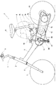
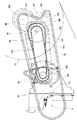
図1は本発明の一実施形態に関係するペダル付き自動二輪車1の側面図である。ヘッドパイプ2から後方斜め下向きに板金製箱型断面の車体フレーム3が延出している。ヘッドパイプ2にステアリングシャフト4が軸支され、ステアリングシャフト4の上部に左右に展開したハンドル5が設けられ、ステアリングシャフト4から下方へ延出したフロントフォーク6に前輪7が軸支されている。車体フレーム3の後端部に、パイプ製シートポスト8が、その一対の下端部で接続され、同シートポスト8の上端にシート9が設けられている。
FIG. 1 is a side view of a motorcycle 1 with a pedal related to one embodiment of the present invention. A body frame 3 having a sheet metal box-shaped cross section extends rearward and obliquely downward from the
車体フレーム3の下部に頭上弁式4ストローク単気筒内燃機関10が搭載固定され、同内燃機関10の前方、且つ車体フレーム3の下部に、人力駆動用ペダル軸11が回転可能に装備されている。内燃機関10の左側面に動力伝達ケース12が固定され、その後端部には、後輪13が回転可能に支持されている。車体フレーム3と内燃機関10と動力伝達ケース12とは相互に固定されている。
An overhead valve type 4-stroke single-cylinder
動力伝達ケース12の中には、内燃機関10の動力を後輪13に伝達する動力伝達機構14が収納され、動力伝達ケース12の外側には、ペダル踏力を後輪13に伝達するペダル踏力伝達機構15が設けられている。シートポスト8の下部には、燃料タンク16、エアクリーナ17、気化器18が設けられ、シートポスト8の一対のパイプに挟まれた部分は、ヘルメットの置き場所19となっている。なお、26はペダルアーム、27はペダルである。
The
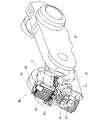
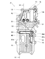
図2は上記実施形態における内燃機関10と動力伝達ケース12の外観図である。内燃機関10の外観は、クランクケース20、シリンダヘッド21、シリンダヘッドカバー22から構成されている。シリンダ30はクランクケース20内に収納されているので、外部からは見えない。クランクケース20の右側には、発電機収納部23が一体的に設けてある。上記発電機収納部23の外側に発電機カバー24が設けてある。シリンダヘッド21の前面中央部に点火プラグ25が見える。
FIG. 2 is an external view of the
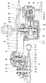
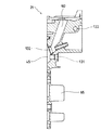
図3は上記パワーユニットのほぼ水平方向の断面を上から見た図、図4は上記内燃機関の縦断面を左側から見た図、図5は上記内燃機関のシリンダヘッドカバーを取り除き、特にシリンダヘッドの内部を見えるようにした正面図、図6は動力伝達機構14とペダル踏力伝達機構15を示した側面図である。
3 is a diagram showing a cross section of the power unit in a substantially horizontal direction from above, FIG. 4 is a diagram showing a longitudinal section of the internal combustion engine as seen from the left side, and FIG. 5 is a view of removing the cylinder head cover of the internal combustion engine. FIG. 6 is a side view showing the
図3、図4において、内燃機関10の外殻はクランクケース20、シリンダヘッド21、シリンダヘッドカバー22によって構成されている。上記クランクケース20は、ほぼ水平方向に傾斜したシリンダ30を収納すると共に、シリンダ30の下方に、シリンダ軸線方向前方に開口部を有するオイルパン部80が形成され、上記シリンダヘッド21が上記オイルパン部80の開口を覆っている。シリンダ30はシリンダヘッド21にボルト31によって固定されており、シリンダヘッド21はクランクケース20にボルト28で固定されている。したがって、シリンダ30はクランクケース20内にて、シリンダヘッド21に片持ち式にほぼ水平方向に傾斜して保持された状態となっている。上記シリンダヘッド21において、上記クランクケースに対する接合面と上記シリンダに対する接合面とは、同一平面上に形成されている。シリンダ30の外周にはシリンダ軸線に平行な複数のフィン32が設けてある。
3 and 4, the outer shell of the
図3、図4において、クランクケース20の後部には、クランク軸35がボールベアリング36A、36Bを介してクランクケース20に回転可能に保持されている。クランク軸35の左端部を支えるボールベアリング36Bは、詳細後述する動力伝達ケース基端部材40を介してクランクケース20に支えられている。クランクピン37にはコンロッド38の大端部が支持され、コンロッド38の小端部はピストン39を支持している。ピストン39は、上記シリンダ30内を摺動可能となっている。クランク軸35に対して車両駆動輪である後輪13は後方に位置し、シリンダ30の軸線は前方へほぼ水平に伸びている。すなわち、後輪13とシリンダ30とは互いに反対方向に位置している。
3 and 4, a
図4、図5において、シリンダヘッド21の、上記ピストン39に対向する部分に、燃焼室45が形成され、前述の点火プラグ25と共に、吸気弁46と排気弁47が設けてある。シリンダヘッド21の、上記シリンダ30の頂部前方の内部空間には、上記吸気弁46と排気弁47の軸端部が突出し、これらを駆動する動弁機構48が収容されている。この動弁機構48は頭上弁式である。図4、図5に見られるように、動弁機構48には、カム軸49とロッカアーム軸52があり、カム軸49には吸気カム50と排気カム51が設けられ、ロッカアーム軸52には吸気ロッカアーム53と排気ロッカアーム54が設けてある。カム軸49の端部には従動プーリ55が設けられ、クランク軸に設けられた駆動プーリ56との間に歯付きベルト57が巻き掛けられ、クランク軸35によってカム軸49が回転駆動されるようになっている。図4において、60は吸気ポート、図5において61は排気ポートである。
4 and 5, a
図4において、シリンダヘッドカバー22が上記シリンダヘッド21の頂部にボルト29によって取り付けてあり、シリンダヘッド21の頂部を覆っている。シリンダヘッドカバー22の内部にはブリーザ機構の気液分離室58が形成してある。59は気液分離室58の一方の壁面を構成し、動弁機構48との間を仕切る隔壁である。
In FIG. 4, a
図3、図4において、クランクケース20の左面を覆う動力伝達ケース12の基端部材40に、その内側からオイルポンプ70が取り付けてある。オイルポンプ軸71には、従動歯車72が設けられ、クランク軸35に設けられた駆動歯車73と噛合っており、クランク軸35によってオイルポンプ70が駆動されるようになっている。
3 and 4, an
図4において、クランクケース20の下部にはオイルパン部80が形成され、ストレーナ装着溝81にストレーナ82が装着されている。シリンダヘッド21の、上記オイルパン部80を覆う部分に、油路形成部材83と油路蓋部材84とによって吸入油路85と吐出油路86が形成されている。上記吸入油路85とオイルポンプ70の吸入口74との間には吸入パイプ87が架け渡してあり、上記吐出油路86とオイルポンプ70の吐出口75との間には吐出パイプ88が架け渡してある。上記吸入パイプ87および吐出パイプ88はいずれもシリンダ30の下方に設けてあり、シリンダ30の軸線に沿って配置されている。オイルパン部80に流入し、ストレーナ82を通過して上方へ昇ったオイルは、オイル吸入孔95、吸入油路85、吸入パイプ87を経由してオイルポンプ70に吸入され、オイルポンプ70で加圧されて、吐出パイプ88、吐出油路86を経由して吐出される。
In FIG. 4, an
図5において、上記の吐出されたオイルは、上記吐出油路86に続く油路89、90、91、92、93、94を経由して動弁機構48へ噴射される。オイルの通路は、吐出油路86の端部から壁体内油路89によってクランクケース20の端面に設けられた油路90につながり、油路90の端部から壁体内油路91によってシリンダヘッド21の端面に設けられた油路92につながり、壁体内油路93を経てオイル噴射孔94に至る。オイルはオイル噴射孔94から動弁機構48へ噴射される。
In FIG. 5, the discharged oil is injected to the
図4において、オイルポンプには動力伝達ケース基端部材40への接合面に吐出口75に連なるオイルポンプ内油路76が設けてあり、その端部に連通するオイル噴射孔77が設けてある。加圧されたオイルが、このオイル噴射孔77からコンロッド38の大端部へ向けて噴射され、クランク軸35との間の摺動部が潤滑される。動弁機構48、コンロッド38の大端部、クランク軸35等へ噴射されたオイルは、シリンダヘッド21、クランクケース20内を流下して、オイルパン部80へ落下して溜まり、再びオイルポンプ70に吸入され、加圧されて、循環する。また、シリンダヘッド内でカム軸等の動弁機構がシリンダ軸線より上方に設けてあり、かつシリンダヘッドは車体に搭載した状態で、若干後部が下がっているので、シリンダヘッド内からのオイルの戻りを良好に維持することができる。
In FIG. 4, the oil pump is provided with an oil pump
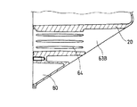
図5において、この内燃機関10には、上記吸入パイプ87、吐出パイプ88とほぼ平行に、シリンダヘッド21の前面からクランクケース20の後面に抜ける冷却風通路63が設けてある。この冷却風通路63は、シリンダヘッド部分63Aとクランクケース部分63Bとからなっている。クランクケース部分63Bの内面には前後方向に伸びる複数のフィン64が設けてあり、クランクケース内を飛散あるいは流下するオイルを冷却するようになっている。また、図4、図5において、シリンダヘッド21の、上記オイルパン部80を覆う壁体部の前面にもフィン65が設けてあり、クランクケース20の内部および油路の冷却に役立っている。またシリンダヘッドカバー22の前面にもフィン66が設けてあり(図4)、気液分離室58内のオイルの冷却に役立っている。
In FIG. 5, the
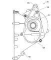
図3において、クランクケース20の右面には発電機収納部23が設けてあり、発電機68が収納されている。発電機68は、クランクケース20の右側面から外方へ突出したクランク軸35の端部によって回転駆動される。発電機収納部23は、通風隙間を有する発電機カバー24で覆われている。
In FIG. 3, a
図3において、動力伝達ケース12は、その基端部材40に順次組み付けられる内側部材41、外側部材42、後部部材43によって形成されている。上記基端部材40は動力伝達ケース12の一部をなすと共に、クランクケース左壁の開口部の蓋を兼ねている。
In FIG. 3, the
自動二輪車1には、前から順に、ペダル軸11、クランク軸35、従動軸96、中間軸97、および後車軸98の5本の回転軸が設けてある。ペダル軸11は車体フレーム3に回転可能に支持されている。クランク軸35は、クランクケースの右壁と上記動力伝達ケース12の基端部材40にそれぞれボールベアリング36A、36Bを介して回転可能に支持されている。従動軸96、中間軸97、および後車軸98は、何れも動力伝達ケース12の内側部材41と後部部材43とによって回転可能に支持されている。従動軸96と後車軸98はボールベアリングを介して支持されている。
The motorcycle 1 is provided with five rotating shafts of a
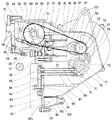
図3および図6において、クランク軸35、従動軸96、中間軸97、および後車軸98は、内燃機関10から後輪13への動力伝達に係る軸である。クランク軸35の左端部にドライブプーリ100が設けられ、従動軸96にドリブンプーリ101が回転自在に設けられ、この両プーリ間に無端状Vベルト102が架渡されて、Vベルト式無段変速機103が構成されている。図6には、Vベルト102の、低変速比の位置と高変速比の位置とが示してある。従動軸96の左端部に設けられた遠心クラッチ104がドリブンプーリ101と従動軸96との間を系脱している。従動軸96に設けられた小径歯車105と中間軸97に設けられた大径歯車106が噛合い、中間軸97に設けられた小径歯車107と後車軸98にワンウエイクラッチ108を介して装着された大径歯車109とが噛合って、減速歯車機構110が構成されている。Vベルト無段変速機103と減速歯車機構110とによって、動力伝達機構14が構成されている。動力伝達機構14は動力伝達ケース12に収納されている。上記Vベルト102は第1の無端状伝動部材である。
In FIGS. 3 and 6, a
図3において、ペダル軸11の左端部にドライブスプロケット112が取り付けてある。運転者の、ペダル27の踏力は、ペダルアーム26、およびペダル軸11を経て伝達され、ドライブスプロケット112が回転駆動される。後車軸98にワンウエイクラッチ113を介してドリブンスプロケット114が軸支されている。この両スプロケット間に無端状チェーン115が架渡され、ぺダル踏力が無端状チェーン115を介して後輪13に伝達される。後輪13の回転はワンウエイクラッチ113の作用によりペダル27には伝達されない。図6に示されるように、無端状チェーン115には、アイドルプーリ116とテンショナプーリ117の作用によって張力が加えられている。上記各部材によってペダル踏力伝達機構15が構成される。ペダル踏力伝達機構15の無端状チェーン115は上記動力伝達ケース12の外側に配置されている。上記無端状チェーン115は第2の無端状伝動部材である。
In FIG. 3, a
図4および図5に見られるように、吸気弁46、排気弁47や、動弁機構48のカム軸49、ロッカアーム軸52等はシリンダ30の軸線方向前方を避けて、上方へ偏移させてある。これによって、シリンダヘッドの軸線に対して動弁機構とは反対側の空間、即ち動弁機構の下側の空間が空く。図4および図6に見られるように、この空き空間部にペダル軸11が設けてある。これによって、ペダル軸をクランク軸に近づけることが出来る。
As shown in FIGS. 4 and 5, the
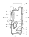
図7はクランクケース20の正面図、図8はクランクケース20の右面図(図7のVIII矢視図)、図9はクランクケース20の左面図(図7のIX矢視図)、図10は図7のX−X断面図である。クランクケース20は、前部が開口した有底箱状に形成されている。
7 is a front view of the
図7において、上記前部開口の周囲にはシリンダヘッド21との接合面120が形成され、その面にパッキン溝121が形成され、複数のシリンダヘッド接続用ねじ孔122が設けてある。上記接続面の一部に、前述のクランクケース端面油路90(図5)が穿設してある。クランクケース20内の上半部は、シリンダ収納空間123となっている。
In FIG. 7, a joining
図8において、クランクケース20の右面には発電機収納部23が設けてあり、中央部にクランク軸挿通孔124が設けてある。側面にフィン67が一体に形成してある。上部と下部に、内燃機関10を車体へ取付けるためのボルト挿通孔125が一体に形成してある。
In FIG. 8, a
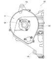
図9において、クランクケース20の左面中央部には大きいクランクケース左壁開口126が設けてある。このクランクケース左壁開口は動力伝達ケース基端部材40によって覆われる部分である。開口126の周囲は上記基端部材接合面127となっており、その周囲には複数の基端部材取り付け用ねじ孔128が設けてある。
In FIG. 9, a large crankcase left wall opening 126 is provided at the center of the left surface of the
図4と図7において、クランクケース20の下部、上記シリンダ収納空間123の下方に、シリンダ軸線方向前方に開口部を有するオイルパン部80が形成されている。この部分は、シリンダヘッド21に覆われて、クランクケース内部を流下した潤滑オイルが溜まるようになっている。オイルパン部80にはストレーナ装着溝81(図7)が形成されており、ここにストレーナ82を嵌め込んだ後、この開口部をシリンダヘッド21で覆うと、図4の状態となる。クランクケース下部中央のオイルパン部隔壁80aに連通孔80bが設けてある。
4 and 7, an
図7と図10において、クランクケース20には、前部開口面に直交し、前部から後部へ貫通する冷却風通路63のクランクケース部分63Bが設けてある。これは、冷却風通路63のシリンダヘッド部分63Aと対応する位置にあり、車両走行中に走行風が通過するようになっている。上記冷却風通路63Bの内面には複数のフィン64が形成され、クランクケース内部を飛散・流下するオイルの冷却効果の向上が図られている。
7 and 10, the
図11はシリンダヘッド21の正面図、図12は図11のXI−XI断面図である。図11において、上部にはシリンダヘッドカバー接合面129が設けてあり、周囲に複数のシリンダヘッドカバー取り付け用ねじ孔130が設けてある。シリンダヘッド21の、クランクケース20のオイルパン部80を覆う部分には、前述のオイル吸入孔95、吸入油路85、吸入パイプ87への入口87A、吐出パイプ88からの出口88A、吐出油路86、および壁体内油路89が設けてある。シリンダヘッドカバー接合面129には、上記壁体内油路89に連通する壁体内油路91、シリンダヘッド端面油路92、壁体内油路93、およびオイル噴射孔94が穿設されている。中央部に点火プラグ取り付け孔131と排気ポート61が設けてある。下部のクランクケースのオイルパン部を覆う部分の外面には多数のフィン65が設けてあり、その中に冷却風通路のシリンダヘッド部分63Aが開口している。
11 is a front view of the
図12において、中央部に燃焼室45と点火プラグ取り付け孔131と吸気弁取り付け部132が見える。また吸気弁取り付け部132から上方へ吸気ポート60が伸びている。燃焼室45の周囲部はシリンダ30の接合面であり、図12の上下端部はクランクケースへの接合面である。シリンダ30の接合面とクランクケース20への接合面は同一平面を成している。133はロッカーアーム軸支持孔である。
In FIG. 12, the
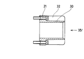
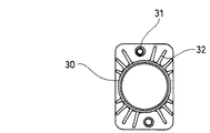
図13はシリンダ30の縦断面図、図14は図13のXIV矢視図である。シリンダ30はボルト31によってシリンダヘッド21に固定される。シリンダ30の側面には多数のフィン32が設けてあり、クランクケース20内で飛散するオイルによって冷却される。
FIG. 13 is a longitudinal sectional view of the
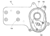
図15は動力伝達ケース基端部材40をクランクケース20側から見た平面図である。動力伝達ケース基端部材40は、図3に示されるように、動力伝達ケース12の一部を構成すると共に、図9に示したクランクケース左壁開口126の蓋となっている。図15の136は、接合部のパッキン溝である。動力伝達ケース基端部材40のクランクケース左壁開口126の蓋となる部分にはクランク軸挿通孔137が設けてあり、図3に示したボールベアリング36Bを介してクランク軸35を支える。クランク軸挿通孔137の下方にオイルポンプ取り付け部138が設けてある。図3、図4に示したオイルポンプ70は、クランクケース20の内側となるように取り付けられる。図15の動力伝達ケース基端部材40の左半部は動力伝達ケース12を構成する部材の取り付け部であり、複数のボルト挿通孔139によって動力伝達ケース12が組み付けられる。
FIG. 15 is a plan view of the power transmission case
以上に詳述したように、本実施形態においては、
(1)クランクケースの中にシリンダを収容する空間を備え、シリンダがシリンダヘッドに片持ち支持され、該シリンダを、クランクケース内に収容するので、内燃機関の構造を簡単化しつつ組立て性を向上することができる。
(2)上記クランクケースは、シリンダヘッドとの接合面を開口部とする有底箱状に形成され、該箱状の一側面がカバーにより覆われて発電機を収容する補機室を形成し、他側面が動力伝達ケースにより覆われているので、簡易な構造によって、パワーユニットを形成し、小型化およびコストダウンを図ることができる。
(3)クランクケースとシリンダとシリンダヘッドとを独立に作ってそれぞれをボルトで結合して組立てるので、生産性が向上する。また、上記各部材の接合面を同一平面上に形成しているので、シリンダヘッドの加工性が向上し、寸法精度の向上により密封性が向上する。
(4)シリンダヘッド外面、クランクケース外面、冷却風通路内面等に設けられたフィンに沿って流れる空気によって冷却された潤滑オイルを介して、シリンダの外周を冷却することができるので、効果的な液体による冷却構造を簡単に形成することができる。
As described in detail above, in this embodiment,
(1) A space for accommodating the cylinder is provided in the crankcase, the cylinder is cantilevered by the cylinder head, and the cylinder is accommodated in the crankcase, so that the structure of the internal combustion engine is simplified and the assembly is improved. can do.
(2) The crankcase is formed in a bottomed box shape with the joint surface with the cylinder head as an opening, and one side surface of the box shape is covered with a cover to form an auxiliary machine chamber that houses the generator. Since the other side surface is covered with the power transmission case, the power unit can be formed with a simple structure, and the size and cost can be reduced.
(3) Since the crankcase, the cylinder, and the cylinder head are independently made and assembled by connecting them with bolts, productivity is improved. Further, since the joint surfaces of the respective members are formed on the same plane, the workability of the cylinder head is improved, and the sealing performance is improved by improving the dimensional accuracy.
(4) Since the outer periphery of the cylinder can be cooled through the lubricating oil cooled by the air flowing along the fins provided on the outer surface of the cylinder head, the outer surface of the crankcase, the inner surface of the cooling air passage, etc., it is effective. A liquid cooling structure can be easily formed.
12…動力伝達ケース、20…クランクケース、21…シリンダヘッド、22…シリンダヘッドカバー、23…発電機収納部、24…発電機カバー、30…シリンダ、32…フィン、35…クランク軸、39…ピストン、40…動力伝達ケース基端部材、63…冷却風通路、64…フィン(冷却風通路内)、65…フィン(シリンダヘッド下部)、67…フィン(クランクケース右側外面)、68…発電機。
12 ... Power transmission case, 20 ... Crank case, 21 ... Cylinder head, 22 ... Cylinder head cover, 23 ... Generator housing, 24 ... Generator cover, 30 ... Cylinder, 32 ... Fin, 35 ... Crank shaft, 39 ...
Claims (4)
上記シリンダは、シリンダヘッドに片持ち支持され、
上記クランクケースは、クランク軸を支持すると共に、上記シリンダを収容する空間を内部に備えることを特徴とする内燃機関の構造及びその冷却構造。 In the structure of an internal combustion engine provided with a crankcase, a cylinder and a cylinder head and its cooling structure,
The cylinder is cantilevered by the cylinder head,
An internal combustion engine structure and a cooling structure thereof, wherein the crankcase includes a space for supporting the crankshaft and accommodating the cylinder.
Priority Applications (1)
| Application Number | Priority Date | Filing Date | Title |
|---|---|---|---|
| JP2004105714A JP2005291053A (en) | 2004-03-31 | 2004-03-31 | Structure of internal combustion engine and cooling structure thereof |
Applications Claiming Priority (1)
| Application Number | Priority Date | Filing Date | Title |
|---|---|---|---|
| JP2004105714A JP2005291053A (en) | 2004-03-31 | 2004-03-31 | Structure of internal combustion engine and cooling structure thereof |
Publications (1)
| Publication Number | Publication Date |
|---|---|
| JP2005291053A true JP2005291053A (en) | 2005-10-20 |
Family
ID=35324277
Family Applications (1)
| Application Number | Title | Priority Date | Filing Date |
|---|---|---|---|
| JP2004105714A Pending JP2005291053A (en) | 2004-03-31 | 2004-03-31 | Structure of internal combustion engine and cooling structure thereof |
Country Status (1)
| Country | Link |
|---|---|
| JP (1) | JP2005291053A (en) |
-
2004
- 2004-03-31 JP JP2004105714A patent/JP2005291053A/en active Pending
Similar Documents
| Publication | Publication Date | Title |
|---|---|---|
| US6598595B2 (en) | Breather device for motorcycle | |
| US7743758B2 (en) | Breather structure for internal combustion engine | |
| CN101907008B (en) | Motorcycle engine ventilating device | |
| KR101063066B1 (en) | Cooling structure of belt type continuously variable transmission | |
| JP2002097917A (en) | Engine unit for vehicle | |
| JP2010174715A (en) | Internal combustion engine | |
| JP3539517B2 (en) | Starter motor mounting arrangement structure for unit swing internal combustion engine | |
| JP2013060812A (en) | Oil cooler structure of internal combustion engine | |
| JP2011105148A (en) | Power unit for vehicle | |
| JP4425646B2 (en) | Auxiliary structure for internal combustion engine | |
| JPH0119045B2 (en) | ||
| JP6205974B2 (en) | Engine oil strainer structure | |
| CN102834592B (en) | Engine oil passage structure | |
| JP2005291052A (en) | Lubrication structure of internal combustion engine | |
| JP2005351115A (en) | Oil pump mounting structure for internal combustion engine | |
| JP2011190787A (en) | Blow-by gas ventilation structure of internal combustion engine | |
| JP2005291053A (en) | Structure of internal combustion engine and cooling structure thereof | |
| JP4556611B2 (en) | Motorcycle power unit | |
| JP2005306228A (en) | Internal combustion engine structure of a motorcycle with a pedal | |
| JP6160335B2 (en) | Parallel multi-cylinder engine | |
| JP3835426B2 (en) | Scooter type vehicle | |
| JP2005030325A (en) | Motorcycle engine and motorcycle equipped with the engine | |
| JP2001130469A (en) | Scooter type vehicle | |
| JP2006090241A (en) | 4-cycle engine for motorcycles | |
| JP2004011505A (en) | Lubricating oil supply structure of internal combustion engine |