JP2005291001A - diesel engine - Google Patents
diesel engine Download PDFInfo
- Publication number
- JP2005291001A JP2005291001A JP2004103049A JP2004103049A JP2005291001A JP 2005291001 A JP2005291001 A JP 2005291001A JP 2004103049 A JP2004103049 A JP 2004103049A JP 2004103049 A JP2004103049 A JP 2004103049A JP 2005291001 A JP2005291001 A JP 2005291001A
- Authority
- JP
- Japan
- Prior art keywords
- fuel injection
- ignition timing
- timing
- fuel
- air
- Prior art date
- Legal status (The legal status is an assumption and is not a legal conclusion. Google has not performed a legal analysis and makes no representation as to the accuracy of the status listed.)
- Pending
Links
Images
Classifications
-
- F—MECHANICAL ENGINEERING; LIGHTING; HEATING; WEAPONS; BLASTING
- F02—COMBUSTION ENGINES; HOT-GAS OR COMBUSTION-PRODUCT ENGINE PLANTS
- F02D—CONTROLLING COMBUSTION ENGINES
- F02D41/00—Electrical control of supply of combustible mixture or its constituents
- F02D41/30—Controlling fuel injection
- F02D41/3011—Controlling fuel injection according to or using specific or several modes of combustion
- F02D41/3017—Controlling fuel injection according to or using specific or several modes of combustion characterised by the mode(s) being used
- F02D41/3035—Controlling fuel injection according to or using specific or several modes of combustion characterised by the mode(s) being used a mode being the premixed charge compression-ignition mode
-
- F—MECHANICAL ENGINEERING; LIGHTING; HEATING; WEAPONS; BLASTING
- F02—COMBUSTION ENGINES; HOT-GAS OR COMBUSTION-PRODUCT ENGINE PLANTS
- F02D—CONTROLLING COMBUSTION ENGINES
- F02D35/00—Controlling engines, dependent on conditions exterior or interior to engines, not otherwise provided for
- F02D35/02—Controlling engines, dependent on conditions exterior or interior to engines, not otherwise provided for on interior conditions
- F02D35/028—Controlling engines, dependent on conditions exterior or interior to engines, not otherwise provided for on interior conditions by determining the combustion timing or phasing
-
- F—MECHANICAL ENGINEERING; LIGHTING; HEATING; WEAPONS; BLASTING
- F02—COMBUSTION ENGINES; HOT-GAS OR COMBUSTION-PRODUCT ENGINE PLANTS
- F02D—CONTROLLING COMBUSTION ENGINES
- F02D41/00—Electrical control of supply of combustible mixture or its constituents
- F02D41/30—Controlling fuel injection
- F02D41/38—Controlling fuel injection of the high pressure type
- F02D41/40—Controlling fuel injection of the high pressure type with means for controlling injection timing or duration
- F02D41/401—Controlling injection timing
-
- F—MECHANICAL ENGINEERING; LIGHTING; HEATING; WEAPONS; BLASTING
- F02—COMBUSTION ENGINES; HOT-GAS OR COMBUSTION-PRODUCT ENGINE PLANTS
- F02D—CONTROLLING COMBUSTION ENGINES
- F02D41/00—Electrical control of supply of combustible mixture or its constituents
- F02D41/0025—Controlling engines characterised by use of non-liquid fuels, pluralities of fuels, or non-fuel substances added to the combustible mixtures
- F02D41/0047—Controlling exhaust gas recirculation [EGR]
- F02D41/005—Controlling exhaust gas recirculation [EGR] according to engine operating conditions
- F02D41/0057—Specific combustion modes
-
- Y—GENERAL TAGGING OF NEW TECHNOLOGICAL DEVELOPMENTS; GENERAL TAGGING OF CROSS-SECTIONAL TECHNOLOGIES SPANNING OVER SEVERAL SECTIONS OF THE IPC; TECHNICAL SUBJECTS COVERED BY FORMER USPC CROSS-REFERENCE ART COLLECTIONS [XRACs] AND DIGESTS
- Y02—TECHNOLOGIES OR APPLICATIONS FOR MITIGATION OR ADAPTATION AGAINST CLIMATE CHANGE
- Y02T—CLIMATE CHANGE MITIGATION TECHNOLOGIES RELATED TO TRANSPORTATION
- Y02T10/00—Road transport of goods or passengers
- Y02T10/10—Internal combustion engine [ICE] based vehicles
- Y02T10/40—Engine management systems
Landscapes
- Engineering & Computer Science (AREA)
- Chemical & Material Sciences (AREA)
- Combustion & Propulsion (AREA)
- Mechanical Engineering (AREA)
- General Engineering & Computer Science (AREA)
- Electrical Control Of Air Or Fuel Supplied To Internal-Combustion Engine (AREA)
- Output Control And Ontrol Of Special Type Engine (AREA)
- Exhaust-Gas Circulating Devices (AREA)
- Combined Controls Of Internal Combustion Engines (AREA)
Abstract
【課題】 予混合燃焼における混合気の着火時期又は予混合期間を最適に制御できるディーゼルエンジンを提供する。
【解決手段】 燃料噴射装置9,24,25と、EGR装置19と、燃料の噴射終了後に混合気が着火する予混合燃焼を実行するように燃料噴射装置9,24,25及びEGR装置19を制御する制御装置26と、を備えたディーゼルエンジンであって、混合気の着火時期を検出する検出手段31を更に備え、上記制御装置26は、上記検出手段31により検出される実際の着火時期が予め定められた最適着火時期とずれているときには、上記燃料噴射装置9,24,25による燃料の噴射時期を補正して、実際の着火時期を上記最適着火時期に一致させるものである。
【選択図】 図1
PROBLEM TO BE SOLVED: To provide a diesel engine capable of optimally controlling an ignition timing or a premixing period of an air-fuel mixture in premixed combustion.
SOLUTION: Fuel injectors 9, 24, 25, EGR device 19, and fuel injectors 9, 24, 25 and EGR device 19 so as to execute premixed combustion in which an air-fuel mixture ignites after completion of fuel injection. And a control unit 26 for controlling the diesel engine, further comprising a detection means 31 for detecting the ignition timing of the air-fuel mixture, and the control apparatus 26 determines the actual ignition timing detected by the detection means 31. When it deviates from the predetermined optimal ignition timing, the fuel injection timing by the fuel injection devices 9, 24, 25 is corrected to make the actual ignition timing coincide with the optimal ignition timing.
[Selection] Figure 1
Description
本発明は、予混合燃焼を実行するディーゼルエンジンに係り、特に、予混合燃焼における混合気の着火時期又は予混合期間の最適化を図ったディーゼルエンジンに関するものである。 The present invention relates to a diesel engine that performs premixed combustion, and more particularly to a diesel engine that optimizes the ignition timing or premixing period of a mixture in premixed combustion.
従来、ディーゼルエンジンでは、筒内が高温・高圧となるピストンの圧縮上死点近傍で燃料を噴射するのが一般的であった。この場合、燃料の噴射中に燃料(混合気)が着火して火炎が形成され、その火炎に後続の燃料が供給されることで燃焼が継続される。このような従来の燃焼形態では、初期に噴射した燃料が着火遅れ期間の後一気に燃焼する部分と、空気が不足する燃焼ガス中での燃焼部分とが存在し、NOxやスモーク等が発生するという問題が指摘されていた。 Conventionally, in a diesel engine, it is common to inject fuel near the compression top dead center of a piston in which the inside of the cylinder becomes high temperature and high pressure. In this case, the fuel (air-fuel mixture) is ignited during fuel injection to form a flame, and the subsequent fuel is supplied to the flame so that combustion is continued. In such a conventional combustion mode, there are a portion where the fuel injected at an early stage burns at once after the ignition delay period and a combustion portion in the combustion gas where air is insufficient, and NOx, smoke, etc. are generated. The problem was pointed out.
そこで本出願人は、燃料の噴射時期を圧縮上死点よりも早期にし、燃料の噴射終了後に混合気が着火するようにしたディーゼルエンジンを提案した(特許文献1参照)。 Therefore, the present applicant has proposed a diesel engine in which the fuel injection timing is made earlier than the compression top dead center so that the air-fuel mixture is ignited after the fuel injection is completed (see Patent Document 1).
このディーゼルエンジンでは、燃料の噴射終了後、ある程度の期間を経て混合気が着火するため、着火までに混合気が充分に希薄・均一化される。従って、局所的な燃焼温度が下がりNOx排出量が低減する。また、局所的に空気不足状態での燃焼も回避されるのでスモークの発生も抑制される。 In this diesel engine, the air-fuel mixture is ignited after a certain period of time after the fuel injection is completed, so that the air-fuel mixture is sufficiently diluted and made uniform before ignition. Therefore, the local combustion temperature is lowered and the NOx emission amount is reduced. Moreover, since the combustion in the air-deficient state is also avoided locally, the occurrence of smoke is suppressed.
このように、燃料の噴射終了後に混合気が着火する燃焼形態を本明細書では予混合燃焼と称し、燃料の噴射が終了してから混合気が着火するまでの期間を予混合期間と称する。 In this specification, the combustion mode in which the air-fuel mixture ignites after completion of fuel injection is referred to as premix combustion, and the period from the end of fuel injection until the air-fuel mixture ignites is referred to as premixing period.
ところで、排気ガスの改善に有効な予混合燃焼であるが、この燃焼を実現するに際して以下に示す二つの課題を抱えていた。 By the way, the premixed combustion is effective for improving the exhaust gas. However, when realizing this combustion, the following two problems have been encountered.
1)予混合期間の確保の困難さ:燃料噴射量が比較的多い運転領域などでは、燃料を早期に噴射しても、燃料の噴射中に混合気が着火してしまう場合がある。この場合、混合気の燃焼形態が従来の燃焼と同じになるため、排気ガスの改善効果を得られなくなる。 1) Difficulty in securing the premixing period: In an operation region where the fuel injection amount is relatively large, the air-fuel mixture may ignite during fuel injection even if fuel is injected early. In this case, since the combustion mode of the air-fuel mixture becomes the same as that of the conventional combustion, the effect of improving exhaust gas cannot be obtained.
2)混合気の着火時期制御の困難さ:燃料の噴射中に着火が始まる従来の燃焼形態では、燃料噴射時期を制御することで着火時期を制御できるが、予混合燃焼では予混合期間が存在し、着火時期が筒内温度、筒内圧力、空燃比等の外部パラメータによって支配されるため、燃料噴射時期の制御だけでは着火時期を正確に制御できない。予混合燃焼において、混合気の着火時期が適切でないと、排気ガスの改善効果を得られないうえ、効率悪化(燃費悪化)や燃焼騒音の発生等にもつながる。例えば、混合気の着火時期が早すぎる(上死点よりも前)と、熱損失の増大を招くと共に、着火後にピストンによる圧縮を受けるため、筒内が高温となり、NOxが発生したり、燃費が悪化したりしてしまう虞がある。 2) Difficulties in controlling the ignition timing of the air-fuel mixture: In the conventional combustion mode in which ignition starts during fuel injection, the ignition timing can be controlled by controlling the fuel injection timing, but premix combustion has a premixing period. However, since the ignition timing is governed by external parameters such as in-cylinder temperature, in-cylinder pressure, and air-fuel ratio, the ignition timing cannot be accurately controlled only by controlling the fuel injection timing. In premixed combustion, if the ignition timing of the air-fuel mixture is not appropriate, an exhaust gas improvement effect cannot be obtained, leading to deterioration in efficiency (deterioration of fuel consumption) and generation of combustion noise. For example, if the ignition timing of the air-fuel mixture is too early (before the top dead center), heat loss increases and compression by the piston occurs after ignition, resulting in a high temperature in the cylinder, generating NOx, and fuel consumption May get worse.
本出願人は、これら二つの課題を克服するには、燃料噴射時期と合わせてEGR率を制御することが有効であることを見いだした。つまり、EGR率を高くすれば、混合気の酸素濃度が低くなるため、予混合期間が長くなる(着火時期が遅くなる)。逆に、EGR率を低くすれば予混合期間が短くなる(着火時期が早くなる)。従って、燃料噴射時期の制御に合わせてEGR率を適切に制御することで、予混合期間及び着火時期を最適に制御することが可能となる。なお、この技術は、本願の出願時において未公開のものであり、従来技術を構成するものではない。 The present applicant has found that it is effective to control the EGR rate in combination with the fuel injection timing in order to overcome these two problems. That is, if the EGR rate is increased, the oxygen concentration of the air-fuel mixture is decreased, so that the premixing period is lengthened (ignition timing is delayed). On the contrary, if the EGR rate is lowered, the premixing period is shortened (the ignition timing is advanced). Therefore, the premixing period and the ignition timing can be optimally controlled by appropriately controlling the EGR rate in accordance with the control of the fuel injection timing. This technology is unpublished at the time of filing of the present application, and does not constitute a conventional technology.
ところが、燃料噴射時期は、インジェクタに対する通電時期を制御することで比較的高精度で制御できるのに対して、EGR率を厳密に制御することは困難であるという問題があった。 However, while the fuel injection timing can be controlled with relatively high accuracy by controlling the energization timing to the injector, there is a problem that it is difficult to strictly control the EGR rate.
例えば、EGR率は、EGR装置に対する制御量(例えば、外部EGR装置におけるEGR弁開度等)以外のパラメータにも影響を受けるため、EGR装置に対する制御量を一定としても、他の要因によりEGR率が変動してしまう場合がある。 For example, since the EGR rate is affected by parameters other than the control amount for the EGR device (for example, the EGR valve opening degree in the external EGR device), even if the control amount for the EGR device is constant, the EGR rate is caused by other factors. May fluctuate.
また、外部EGR装置では、EGR弁の応答遅れがあることや、EGR弁から燃焼室までの距離(吸気経路)に伴う容積部分が存在することから、EGR装置に対する制御量を変化させてから実際に混合気のEGR率が変化するまでに若干の時間遅れが生じる。このため、燃料噴射時期及びEGR装置に対する制御量を変更したときに、両者の間に一時的にミスマッチが生じる場合がある。 In the external EGR device, since there is a response delay of the EGR valve and there is a volume portion associated with the distance from the EGR valve to the combustion chamber (intake path), the actual amount after changing the control amount for the EGR device. However, there is a slight time delay until the EGR rate of the air-fuel mixture changes. For this reason, when the fuel injection timing and the control amount for the EGR device are changed, there may be a temporary mismatch between the two.
このように、EGR率を厳密に制御することが困難であるため、結果として、混合気の着火時期又は予混合期間が一時的に不適切となる可能性があり、排気ガスや燃費の悪化を招いてしまうおそれがあった。 As described above, it is difficult to strictly control the EGR rate. As a result, the ignition timing or the premixing period of the air-fuel mixture may temporarily become inappropriate, and the exhaust gas and fuel consumption may deteriorate. There was a risk of being invited.
そこで、本発明の目的は、予混合燃焼における混合気の着火時期を最適に制御することにある。 Accordingly, an object of the present invention is to optimally control the ignition timing of the air-fuel mixture in the premixed combustion.
また本発明の他の目的は、予混合燃焼における混合気の予混合期間を最適に制御することにある。 Another object of the present invention is to optimally control the premixing period of the air-fuel mixture in the premixed combustion.
上記目的を達成するために本発明は、燃焼室内に燃料を噴射する燃料噴射装置と、排気ガスの一部を燃焼室内に還流するEGR装置と、燃料の噴射終了後に混合気が着火する予混合燃焼を実行するように上記燃料噴射装置及びEGR装置を制御する制御装置と、を備えたディーゼルエンジンであって、混合気の着火時期を検出する検出手段を更に備え、上記制御装置は、上記検出手段により検出される実際の着火時期が予め定められた最適着火時期とずれているときには、上記燃料噴射装置による燃料の噴射時期を補正して、実際の着火時期を上記最適着火時期に一致させるものである。 In order to achieve the above object, the present invention provides a fuel injection device that injects fuel into a combustion chamber, an EGR device that recirculates part of exhaust gas into the combustion chamber, and premixing in which an air-fuel mixture is ignited after fuel injection is completed. And a control device for controlling the fuel injection device and the EGR device so as to perform combustion, and further comprising a detection means for detecting an ignition timing of the air-fuel mixture, and the control device includes the detection device. When the actual ignition timing detected by the means deviates from the predetermined optimum ignition timing, the fuel injection timing by the fuel injection device is corrected so that the actual ignition timing matches the optimum ignition timing. It is.
ここで、上記制御装置はエンジンの運転状態に基づいて目標燃料噴射時期を決定し、その目標燃料噴射時期に従って上記燃料噴射装置を制御するものであり、上記検出手段により検出される実際の着火時期が上記最適着火時期よりも早い場合、上記目標燃料噴射時期を遅角側に補正し、逆に、実際の着火時期が上記最適着火時期よりも遅い場合、上記目標燃料噴射時期を進角側に補正するようにしても良い。 Here, the control device determines a target fuel injection timing based on the operating state of the engine, controls the fuel injection device according to the target fuel injection timing, and an actual ignition timing detected by the detection means. If the ignition timing is earlier than the optimum ignition timing, the target fuel injection timing is corrected to the retarded side. Conversely, if the actual ignition timing is later than the optimum ignition timing, the target fuel injection timing is set to the advance side. You may make it correct | amend.
また、上記検出手段はノックセンサであっても良い。 Further, the detecting means may be a knock sensor.
更に本発明は、燃料噴射装置と、EGR装置と、それら燃料噴射装置及びEGR装置を制御して、燃料の噴射終了後に混合気が着火する予混合燃焼を実行する制御装置と、を備えたディーゼルエンジンであって、上記燃料噴射装置による燃料の噴射が終了してから混合気が着火するまでの予混合期間を計測する計測手段を更に備え、上記制御装置は、上記計測手段により計測される予混合期間が予め定められた最適予混合期間とずれているときには、上記燃料噴射装置による燃料の噴射時期を補正して、実際の予混合期間を上記最適予混合期間に一致させるものである。 Furthermore, the present invention provides a diesel engine including a fuel injection device, an EGR device, and a control device that controls the fuel injection device and the EGR device to perform premixed combustion in which the air-fuel mixture is ignited after fuel injection is completed. The engine further includes measuring means for measuring a premixing period from the end of fuel injection by the fuel injection device to the ignition of the air-fuel mixture, and the control device is preliminarily measured by the measuring means. When the mixing period deviates from a predetermined optimum premixing period, the fuel injection timing by the fuel injection device is corrected to make the actual premixing period coincide with the optimum premixing period.
本発明によれば、予混合燃焼における混合気の着火時期又は予混合期間を最適に制御できるという優れた効果を発揮するものである。 According to the present invention, an excellent effect that the ignition timing or the premixing period of the air-fuel mixture in the premixed combustion can be optimally controlled is exhibited.
以下、本発明の好適な一実施形態を添付図面に基づいて詳述する。 Hereinafter, a preferred embodiment of the present invention will be described in detail with reference to the accompanying drawings.
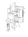
図1は本実施形態のディーゼルエンジン(以下、単にエンジンという)の概略図である。なお、図1では一気筒のみ示されているが、当然多気筒であっても良い。 FIG. 1 is a schematic view of a diesel engine (hereinafter simply referred to as an engine) of the present embodiment. Although only one cylinder is shown in FIG. 1, it is naturally possible to have multiple cylinders.
図中1がエンジン本体であり、これはシリンダ2、シリンダヘッド3、ピストン4、吸気ポート5、排気ポート6、吸気弁7、排気弁8、インジェクタ9等から構成される。シリンダ2とシリンダヘッド3との空間に燃焼室10が形成され、燃焼室10内にインジェクタ9から燃料が直接噴射される。ピストン4の頂部にキャビティ11が形成され、キャビティ11は燃焼室10の一部をなす。キャビティ11は底部中央が隆起したトロイダル型燃焼室の形態をなす。なお、本発明は燃焼室10の形状に制約はなく、リエントラント型燃焼室等であっても良い。
In the figure,
インジェクタ9はシリンダ2と略同軸に配置され、複数の噴孔(ホール)から同時に放射状に燃料を噴射する。インジェクタ9はコモンレール24に接続され、そのコモンレール24に貯留された高圧燃料がインジェクタ9に常時供給される。コモンレール24への燃料圧送は高圧サプライポンプ25により行われる。なお、本願の「特許請求の範囲」における「燃料噴射装置」とは、インジェクタ9、コモンレール24、高圧サプライポンプ25等、燃料の噴射に必要な要素を包括的に称したものである。
The injector 9 is disposed substantially coaxially with the
吸気ポート5は吸気管12に、排気ポート6は排気管13にそれぞれ接続される。
The intake port 5 is connected to the
本実施形態のエンジンは、排気ガスの一部を燃焼室10内に還流する外部EGR装置19を備えている。EGR装置19は、吸気管12と排気管13とを結ぶEGR管20と、EGR管20の管路面積を変えてEGR率を調節するためのEGR弁21と、EGR弁21の上流側にてEGRガスを冷却するEGRクーラ22とを備える。吸気管12においては、EGR管20との接続部の上流側にて吸入空気を適宜絞るための吸気絞り弁23が設けられる。
The engine of the present embodiment includes an external EGR device 19 that recirculates a part of the exhaust gas into the combustion chamber 10. The EGR device 19 includes an
このエンジンを電子制御するためのECU(制御装置)26が設けられる。ECU26は各種センサ類からエンジンの運転状態を読み取り、そのエンジン運転状態に基づいてインジェクタ9、EGR弁21、吸気絞り弁23等を制御する。前記センサ類としては、アクセル開度を検出するアクセル開度センサ14、エンジンの回転速度を検出するエンジン回転センサ15、エンジンのクランク軸(図示せず)の角度を検出するクランク角度センサ16、コモンレール24内の燃料圧力を検出するコモンレール圧センサ17、EGR管20との接続部よりも上流側の吸気管12を流れる吸入空気量(新気流量)を検出する吸気量センサ32等が含まれ、それら各センサの検出値がECU26に入力される。
An ECU (control device) 26 for electronically controlling the engine is provided. The
本実施形態のECU26は、燃料の噴射終了後に混合気が着火する予混合燃焼を実行するようにインジェクタ9及びEGR装置19を制御する。
The
具体的に説明すると、まず、燃料の噴射が完全に終了した後に混合気が着火し、かつ、その着火時期が最適な着火時期(基本的には上死点近傍)となるような燃料噴射時期(噴射開始時期)及びEGR率をエンジンの運転状態毎に予め求めておき、そのデータに基づいて目標燃料噴射時期マップ及び目標EGR弁開度マップを作成してECU26に入力しておく。ECU26は、アクセル開度センサ14やエンジン回転センサ15等の検出値に基づいてエンジンの運転状態を読み取ったならば、上記マップから目標燃料噴射時期及び目標EGR弁開度を決定し、それらに従ってインジェクタ9及びEGR弁21をそれぞれ制御する。予混合燃焼における目標燃料噴射時期は基本的に、従来燃焼で設定される燃料噴射時期(上死点近傍)よりも早期(例えば40〜20°BTDC程度)に設定される。また、目標EGR率は基本的に、従来燃焼で設定されるEGR率よりも高く(例えば、50%以上)設定される。この予混合燃焼によれば、混合気の希薄・均一化が促進されるため、NOx及びスモークを大幅に低減できる。
Specifically, first, the fuel injection timing at which the air-fuel mixture is ignited after the fuel injection is completely completed and the ignition timing is the optimum ignition timing (basically near the top dead center). (Injection start timing) and EGR rate are obtained in advance for each engine operating state, and a target fuel injection timing map and a target EGR valve opening map are created based on the data and input to the
このように本実施形態のディーゼルエンジンは、エンジンの運転状態に応じて燃料噴射時期及びEGR率を制御して予混合燃焼を実行するものであるが、「発明が解決しようとする課題」の欄でも説明したように、EGR率を厳密に制御することは困難である。即ち、マップに従ってEGR弁21の弁開度を制御していても、実際のEGR率が予め定められた最適なEGR率からずれてしまう場合がある。そうなると、混合気の着火時期が最適な着火時期からずれてしまい、燃費や排気ガスの悪化を招いてしまう。
As described above, the diesel engine according to the present embodiment executes the premixed combustion by controlling the fuel injection timing and the EGR rate in accordance with the operating state of the engine. However, as explained, it is difficult to strictly control the EGR rate. That is, even if the valve opening degree of the
そこで、本実施形態のディーゼルエンジンでは、EGR率制御の不安定さに伴う着火時期のずれを防止すべく工夫がなされている。以下、この点について説明する。 Therefore, the diesel engine of the present embodiment is devised to prevent the ignition timing from being shifted due to the instability of EGR rate control. Hereinafter, this point will be described.
本実施形態のディーゼルエンジンは、混合気の着火時期を検出する検出手段として、シリンダブロックに取り付けられたノックセンサ31を備えており、ECU26はノックセンサ31の検出値に基づいて混合気の着火時期を演算・決定する。
The diesel engine of the present embodiment includes a
また、ECU26には混合気の最適な着火時期が予め入力されており、ECU26は、ノックセンサ31の検出値に基づいて決定した実際の着火時期を、その最適な着火時期と比較する。
Moreover, the optimal ignition timing of the air-fuel mixture is input to the
実際の着火時期と最適な着火時期との差(ずれ)が無い場合、現在のEGR率が適切な値に制御されていると推定できる。そこで、この場合、ECU26は通常通りマップに従ってインジェクタ9及びEGR弁21を制御する。
When there is no difference (shift) between the actual ignition timing and the optimum ignition timing, it can be estimated that the current EGR rate is controlled to an appropriate value. Therefore, in this case, the
一方、実際の着火時期と最適な着火時期とにずれがある場合、EGR率が適切な値からずれていると推定できる。例えば、実際の着火時期が最適な着火時期よりも早い場合、EGR率が適切な値よりも低く、混合気の酸素濃度が高くなっていると考えられる。逆に、実際の着火時期が最適な着火時期よりも遅い場合、EGR率が適切な値よりも高く、混合気の酸素濃度が低くなっていると考えられる。 On the other hand, when there is a difference between the actual ignition timing and the optimum ignition timing, it can be estimated that the EGR rate has deviated from an appropriate value. For example, when the actual ignition timing is earlier than the optimal ignition timing, it is considered that the EGR rate is lower than an appropriate value and the oxygen concentration of the air-fuel mixture is high. On the contrary, when the actual ignition timing is later than the optimal ignition timing, it is considered that the EGR rate is higher than an appropriate value and the oxygen concentration of the air-fuel mixture is low.
そこでこのような場合、ECU26は、マップから決定した目標燃料噴射時期を補正して、実際の着火時期を最適な着火時期に一致させる。
Therefore, in such a case, the
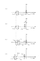
図2(a)〜図2(c)を用いて一例を説明する。 An example will be described with reference to FIGS.
図中横軸がクランク角であり、T1−aがマップから決定した目標燃料噴射時期(噴射開始時期)、T2−aが同じくマップから決定した目標燃料噴射期間、T3−a〜cが混合気の予混合期間、T4−a〜cが混合気の着火時期を表している。また、この例では混合気の最適な着火時期は圧縮上死点(TDC)である。 In the figure, the horizontal axis is the crank angle, T1-a is the target fuel injection timing (injection start timing) determined from the map, T2-a is the target fuel injection period determined from the map, and T3-a to c are the air-fuel mixture. T4-a to c represent the ignition timing of the air-fuel mixture. In this example, the optimal ignition timing of the air-fuel mixture is compression top dead center (TDC).
図2(a)は、EGR率が適切に制御されており、混合気の着火時期が適切である状態を示している。つまり、図から分かるように、燃料の噴射終了後、予混合期間T3−aを経て混合気が着火しており、その着火時期T4−aは最適な着火時期TDCと一致している。よって、排気ガスの浄化効果が高く、かつ燃費も良い良好な燃焼形態であると言える。 FIG. 2A shows a state where the EGR rate is appropriately controlled and the ignition timing of the air-fuel mixture is appropriate. That is, as can be seen from the figure, after the fuel injection is completed, the air-fuel mixture is ignited through the premixing period T3-a, and the ignition timing T4-a coincides with the optimal ignition timing TDC. Therefore, it can be said that this is a good combustion mode with high exhaust gas purification effect and good fuel efficiency.
ところが、何らかの理由(外乱や、EGR率の制御遅れなど)により実際のEGR率が適切な値からずれると、混合気の予混合期間が変化して着火時期がずれる。例えば、EGR率が適切な値よりも低くなると、混合気の酸素濃度が高くなるため、図2(b)に示すように、予混合期間が短く(T3−a→T3−b)なり、着火時期が最適な着火時期TDCよりも早くなる(T4−a→T4−b)。 However, if the actual EGR rate deviates from an appropriate value for some reason (disturbance, EGR rate control delay, etc.), the premixing period of the air-fuel mixture changes and the ignition timing shifts. For example, when the EGR rate is lower than an appropriate value, the oxygen concentration of the air-fuel mixture increases, so that the premixing period is short (T3-a → T3-b) as shown in FIG. The timing is earlier than the optimal ignition timing TDC (T4-a → T4-b).
ECU26は、実際の着火時期が最適な着火時期TDCからずれていることを確認したならば、実際の着火時期が最適な着火時期TDCと一致するように、燃料噴射時期をフィードバック制御する(目標燃料噴射時期T1−aを補正する)。
When the
例えば、図2(b)に示すように、実際の着火時期T4−bが最適な着火時期TDCよりも早い場合、まず、ECU26は、実際の着火時期T4−bと最適な着火時期TDCとの差T5(図2(b)参照)を算出し、その差T5に基づいて目標燃料噴射時期T1−aの補正量ΔTを決定する。より具体的には、実際の着火時期と最適な着火時期との差と、その差をなくすために必要な目標燃料噴射時期の補正量との関係を予め実験などにより求めておき、ECU26に例えば演算式として入力しておく。ECU26は、上述した差T5とその演算式とに基づいて補正量ΔTを決定する。なお、本実施形態では、差T5と補正量ΔTとはほぼ等しいが、本発明はこの点において限定されない。
For example, as shown in FIG. 2B, when the actual ignition timing T4-b is earlier than the optimal ignition timing TDC, first, the
さて、ECU26は目標燃料噴射時期T1−aの補正量ΔTを決定したならば、図2(c)に示すように、目標燃料噴射時期T1−aを補正量ΔTだけ遅角側に補正(T1−a→T1−b)し、その補正後の目標燃料噴射時期T1−bに従ってインジェクタ9に通電する。その結果、混合気の着火時期が遅角側に移動し、最適な着火時期TDCとなる(T4−b→T4−c)。
When the
なお、図2(c)から分かるように、燃料噴射時期を遅角側に補正しても予混合期間T3−cは充分に確保できると考えられる。これは、上述したように、予混合燃焼では、燃料噴射が早期に行われるため噴射時の筒内圧力が低いうえ、多量のEGRにより混合気の酸素濃度が絶対的に低くされるからである。 As can be seen from FIG. 2C, it is considered that the premixing period T3-c can be sufficiently secured even if the fuel injection timing is corrected to the retard side. This is because, as described above, in premixed combustion, fuel injection is performed at an early stage, so that the in-cylinder pressure at the time of injection is low and the oxygen concentration of the air-fuel mixture is absolutely lowered by a large amount of EGR.
燃料噴射時期の補正を行った後、EGR率が適切な値に戻ると、着火時期が遅角側に移動する。ECU26はこれに合わせて燃料噴射時期T1−bを進角側に移動させる。つまり、目標燃料噴射時期T1−aの補正を終了する。これにより、図2(a)に示したような良好な予混合燃焼に再び戻ることができる。
After correcting the fuel injection timing, when the EGR rate returns to an appropriate value, the ignition timing moves to the retard side. In accordance with this, the
また、実際の着火時期が最適な着火時期TDCよりも遅くなった場合は、目標燃料噴射時期T1−aを進角側に補正して、実際の着火時期を最適な着火時期TDCと一致させる。 Further, when the actual ignition timing becomes later than the optimal ignition timing TDC, the target fuel injection timing T1-a is corrected to the advance side so that the actual ignition timing matches the optimal ignition timing TDC.
このように、本実施形態のディーゼルエンジンでは、EGR率が一時的に不適切な値になった場合、燃料噴射時期を補正して着火時期を最適な着火時期に維持する。つまり、燃料噴射時期の高精度性に着目し、EGR率制御の不安定さを燃料噴射時期の補正により補うようにしたものである。また、実際のEGR率を検出又は演算により求めることは非常に困難であるが、本実施形態のディーゼルエンジンは、EGR率と着火時期との相関性に着目し、着火時期を検出することにより実際のEGR率を間接的に推定している。 Thus, in the diesel engine of this embodiment, when the EGR rate temporarily becomes an inappropriate value, the fuel injection timing is corrected and the ignition timing is maintained at the optimal ignition timing. That is, focusing on the high accuracy of the fuel injection timing, the instability of the EGR rate control is compensated by correcting the fuel injection timing. In addition, although it is very difficult to obtain the actual EGR rate by detection or calculation, the diesel engine of this embodiment pays attention to the correlation between the EGR rate and the ignition timing, and actually detects the ignition timing. The EGR rate is estimated indirectly.
本実施形態のディーゼルエンジンによれば、常に適切な着火時期を確保できるため、燃費や排気ガスの悪化等を確実に回避できる。 According to the diesel engine of the present embodiment, it is possible to always ensure an appropriate ignition timing, so it is possible to reliably avoid deterioration of fuel consumption and exhaust gas.
本発明は以上説明した実施形態に限定はされない。 The present invention is not limited to the embodiment described above.
例えば、上記実施形態では、ECU26が、マップから決定した目標EGR弁開度に従ってEGR弁21を制御すると説明したが、本発明はこの点において限定されず、新気流量や混合気の酸素濃度など、EGR率と相関性のある他のパラメータを目標値として設定し、その目標値に従ってEGR弁21を制御しても良い。例えば、新気流量を目標値として設定し、吸気量センサ32(図1参照)の検出値が目標値と一致するようにEGR弁21をフィードバック制御しても良い。
For example, in the above embodiment, the
また、上記実施形態では最適な着火時期を上死点TDCとして説明したが、本発明はこの点において限定されない。更に、最適な着火時期は固定値に限定されず、エンジンの運転状態に基づいて適宜変更するようにしても良い。 Moreover, although the optimal ignition timing was demonstrated as the top dead center TDC in the said embodiment, this invention is not limited in this point. Furthermore, the optimal ignition timing is not limited to a fixed value, and may be changed as appropriate based on the operating state of the engine.
また、着火時期検出手段はノックセンサ31に限定されず、筒内圧センサ、イオンセンサ等、他の手段を用いても良い。しかしながら、ノックセンサ31は他のセンサとしてコストが低いというメリットを有している。
Further, the ignition timing detection means is not limited to the
また、EGR装置は外部EGR装置に限定されず、吸気行程で排気弁を開放する内部EGR装置でも良い。 Further, the EGR device is not limited to the external EGR device, and may be an internal EGR device that opens the exhaust valve in the intake stroke.
ところで、上記実施形態では、EGR率が適切な値からずれた時に、着火時期を最適な着火時期に維持する例を説明したが、以下に述べる第二の実施形態は、予混合燃焼におけるもう一つの重要なパラメータである予混合期間を最適な予混合期間に維持するものである。 In the above embodiment, the example in which the ignition timing is maintained at the optimal ignition timing when the EGR rate deviates from an appropriate value has been described. However, the second embodiment described below is another example in premixed combustion. One important parameter, the premixing period, is maintained at the optimal premixing period.
具体的に説明すると、燃料の噴射が終了してから混合気が着火するまでの実際の予混合期間を常に演算・決定し、実際の予混合期間と予め定められた最適な予混合期間との比較を行い、両者の差(ずれ)に応じて燃料噴射時期を補正する。 Specifically, the actual premixing period from the end of fuel injection to the ignition of the air-fuel mixture is always calculated and determined, and the actual premixing period and a predetermined optimal premixing period are determined. A comparison is made and the fuel injection timing is corrected according to the difference (deviation) between the two.
予混合期間を検出する手段は、燃料の噴射終了時期を検出する手段、上記着火時期検出手段(ノックセンサ31等)、ECU26に内蔵されたタイマ等により構成することが可能である。
The means for detecting the premixing period can be constituted by means for detecting the fuel injection end timing, the ignition timing detecting means (knock
燃料の噴射終了時期は、上述したマップから決定される燃料噴射開始時期と燃料噴射期間とに基づいて、ECU26が判断することができる。即ち、燃料噴射開始時期に燃料噴射期間を足した時期が燃料の噴射終了時期である。あるいは、コモンレール圧センサ24やインジェクタ9のニードル弁のシフト量を検出するセンサ等の検出値に基づいて燃料噴射終了時期を判断しても良い。
The
予混合期間検出手段により検出した実際の予混合期間が最適な予混合期間とずれているときには、EGR率が適切な値からずれていると推定できる。例えば、実際の予混合期間が最適な予混合期間よりも短い場合、EGR率が適切な値よりも低く、混合気の酸素濃度が高くなっていると考えられる。逆に、実際の予混合期間が最適な予混合期間よりも長い場合、EGR率が適切な値よりも高く、混合気の酸素濃度が低くなっていると考えられる。 When the actual premixing period detected by the premixing period detecting means deviates from the optimum premixing period, it can be estimated that the EGR rate deviates from an appropriate value. For example, when the actual premixing period is shorter than the optimum premixing period, it is considered that the EGR rate is lower than an appropriate value and the oxygen concentration of the mixture is high. Conversely, when the actual premixing period is longer than the optimal premixing period, it is considered that the EGR rate is higher than an appropriate value and the oxygen concentration of the air-fuel mixture is low.
そこで、ECU26は、このような場合、実際の予混合期間が最適な予混合期間と一致するように、燃料噴射時期をフィードバック制御する(目標燃料噴射時期を補正する)。
Therefore, in such a case, the
例えば、図2(b)に示した例では、予混合期間T3−bが最適な予混合期間T3−a(図2(a)参照)よりも短くなっているので、この場合、ECU26は、図2(d)に示すように、目標燃料噴射時期を進角側に補正する(T1−a→T1−c)。これにより、燃料噴射時の筒内圧力がより低くなるため予混合期間が長くなり、最適な予混合期間と一致する(T3−d=T3−a)。 For example, in the example shown in FIG. 2B, the premixing period T3-b is shorter than the optimal premixing period T3-a (see FIG. 2A). As shown in FIG. 2D, the target fuel injection timing is corrected to the advance side (T1-a → T1-c). Thereby, since the cylinder pressure at the time of fuel injection becomes lower, the premixing period becomes longer and coincides with the optimal premixing period (T3-d = T3-a).
また、実際の予混合期間が最適な予混合期間T3−aよりも長くなった場合は、目標燃料噴射時期を遅角側に補正して、最適な予混合期間T3−aと一致させる。 When the actual premixing period becomes longer than the optimum premixing period T3-a, the target fuel injection timing is corrected to the retarded side so as to coincide with the optimum premixing period T3-a.
ここで、最適な予混合期間はエンジンの運転状態毎に異なるため、予めマップとしてECU26に入力しておき、ECU26は各種センサ類の検出値からエンジンの運転状態を読み取った後、マップから最適な予混合期間を決定する。
Here, since the optimal premixing period varies depending on the engine operating state, the map is input to the
この実施形態によれば、常に適切な予混合期間を確保することが可能となり、排気ガスの改善効果を効果的に得ることができる。 According to this embodiment, it becomes possible to always ensure an appropriate premixing period, and the effect of improving exhaust gas can be effectively obtained.
1 エンジン本体
9 インジェクタ
19 EGR装置
21 EGR弁
26 ECU(制御装置)
31 ノックセンサ(着火時期検出手段)
DESCRIPTION OF
31 Knock sensor (ignition timing detection means)
Claims (4)
混合気の着火時期を検出する検出手段を更に備え、
上記制御装置は、上記検出手段により検出される実際の着火時期が予め定められた最適着火時期とずれているときには、上記燃料噴射装置による燃料の噴射時期を補正して、実際の着火時期を上記最適着火時期に一致させる
ことを特徴とするディーゼルエンジン。 A fuel injection device that injects fuel into the combustion chamber; an EGR device that recirculates a portion of the exhaust gas into the combustion chamber; and the fuel injection device that executes premixed combustion in which the air-fuel mixture is ignited after fuel injection ends A diesel engine comprising a control device for controlling the EGR device,
It further comprises detection means for detecting the ignition timing of the air-fuel mixture,
When the actual ignition timing detected by the detection means deviates from a predetermined optimum ignition timing, the control device corrects the fuel injection timing by the fuel injection device and sets the actual ignition timing to A diesel engine characterized by matching the optimal ignition timing.
上記検出手段により検出される実際の着火時期が上記最適着火時期よりも早い場合、上記目標燃料噴射時期を遅角側に補正し、逆に、実際の着火時期が上記最適着火時期よりも遅い場合、上記目標燃料噴射時期を進角側に補正する請求項1記載のディーゼルエンジン。 The control device determines a target fuel injection timing based on the operating state of the engine, and controls the fuel injection device according to the target fuel injection timing.
When the actual ignition timing detected by the detection means is earlier than the optimum ignition timing, the target fuel injection timing is corrected to the retard side, and conversely, when the actual ignition timing is later than the optimum ignition timing The diesel engine according to claim 1, wherein the target fuel injection timing is corrected to the advance side.
上記燃料噴射装置による燃料の噴射が終了してから混合気が着火するまでの予混合期間を計測する計測手段を更に備え、
上記制御装置は、上記計測手段により計測される予混合期間が予め定められた最適予混合期間とずれているときには、上記燃料噴射装置による燃料の噴射時期を補正して、実際の予混合期間を上記最適予混合期間に一致させる
ことを特徴とするディーゼルエンジン。
A diesel engine comprising: a fuel injection device; an EGR device; and a control device that controls the fuel injection device and the EGR device to perform premixed combustion in which an air-fuel mixture is ignited after fuel injection is completed.
A measuring means for measuring a premixing period from the end of fuel injection by the fuel injection device until the mixture is ignited;
When the premixing period measured by the measuring means deviates from a predetermined optimum premixing period, the control device corrects the fuel injection timing by the fuel injection device and sets the actual premixing period. A diesel engine characterized by matching with the optimum premixing period.
Priority Applications (4)
| Application Number | Priority Date | Filing Date | Title |
|---|---|---|---|
| JP2004103049A JP2005291001A (en) | 2004-03-31 | 2004-03-31 | diesel engine |
| EP05006309A EP1582729A3 (en) | 2004-03-31 | 2005-03-22 | Diesel engine |
| US11/093,218 US7178505B2 (en) | 2004-03-31 | 2005-03-29 | Diesel engine |
| CNA2005100600834A CN1676910A (en) | 2004-03-31 | 2005-03-31 | Diesel engine |
Applications Claiming Priority (1)
| Application Number | Priority Date | Filing Date | Title |
|---|---|---|---|
| JP2004103049A JP2005291001A (en) | 2004-03-31 | 2004-03-31 | diesel engine |
Publications (1)
| Publication Number | Publication Date |
|---|---|
| JP2005291001A true JP2005291001A (en) | 2005-10-20 |
Family
ID=34880022
Family Applications (1)
| Application Number | Title | Priority Date | Filing Date |
|---|---|---|---|
| JP2004103049A Pending JP2005291001A (en) | 2004-03-31 | 2004-03-31 | diesel engine |
Country Status (4)
| Country | Link |
|---|---|
| US (1) | US7178505B2 (en) |
| EP (1) | EP1582729A3 (en) |
| JP (1) | JP2005291001A (en) |
| CN (1) | CN1676910A (en) |
Cited By (8)
| Publication number | Priority date | Publication date | Assignee | Title |
|---|---|---|---|---|
| JP2008101591A (en) * | 2006-10-20 | 2008-05-01 | Toyota Motor Corp | Ignition timing control device for internal combustion engine |
| JP2008261312A (en) * | 2007-04-13 | 2008-10-30 | Toyota Motor Corp | Fuel injection timing determination device for internal combustion engine |
| JP2009013952A (en) * | 2007-07-09 | 2009-01-22 | Honda Motor Co Ltd | Control device for internal combustion engine |
| JP2009517591A (en) * | 2005-12-02 | 2009-04-30 | ローベルト ボツシユ ゲゼルシヤフト ミツト ベシユレンクテル ハフツング | Method for drive control of a fuel injector of a diesel engine |
| JP2010528226A (en) * | 2007-05-29 | 2010-08-19 | ルノー・トラックス | Method, record carrier and apparatus for adjusting fuel injection |
| WO2011141988A1 (en) * | 2010-05-10 | 2011-11-17 | トヨタ自動車株式会社 | Control device for internal combustion engine |
| WO2013031380A1 (en) * | 2011-08-31 | 2013-03-07 | 株式会社豊田自動織機 | Combustion control apparatus |
| JP2019183729A (en) * | 2018-04-09 | 2019-10-24 | トヨタ自動車株式会社 | Control device for internal combustion engine |
Families Citing this family (10)
| Publication number | Priority date | Publication date | Assignee | Title |
|---|---|---|---|---|
| JP2007023973A (en) * | 2005-07-20 | 2007-02-01 | Honda Motor Co Ltd | Control device for internal combustion engine |
| US7231906B1 (en) * | 2006-06-27 | 2007-06-19 | Gm Global Technology Operations, Inc. | Simultaneous EGR correction and individual cylinder combustion phase balancing |
| BRPI0714495B8 (en) | 2006-07-21 | 2021-05-25 | California Inst Of Techn | Deficient lentivirus for pseudotyped recombinant replication |
| TW200817581A (en) * | 2006-08-29 | 2008-04-16 | Honda Motor Co Ltd | Fuel injection control device |
| DE102007052615A1 (en) * | 2007-11-05 | 2009-05-07 | Volkswagen Ag | Method for operating an internal combustion engine |
| JP5012960B2 (en) * | 2010-06-09 | 2012-08-29 | トヨタ自動車株式会社 | Abnormality determination device for internal combustion engine |
| CN103133178B (en) * | 2011-12-01 | 2015-08-19 | 摩尔动力(北京)技术股份有限公司 | Twin channel entropy cycle engine |
| US9422878B2 (en) * | 2014-04-14 | 2016-08-23 | Ford Global Technologies, Llc | EGR operation method and system for increased drivability |
| JP6897552B2 (en) * | 2017-12-26 | 2021-06-30 | トヨタ自動車株式会社 | Internal combustion engine control device |
| CN113586274B (en) * | 2021-09-14 | 2023-01-24 | 潍柴动力股份有限公司 | Engine injection angle control method and engine |
Family Cites Families (13)
| Publication number | Priority date | Publication date | Assignee | Title |
|---|---|---|---|---|
| JPS5799269A (en) * | 1980-12-11 | 1982-06-19 | Nissan Motor Co Ltd | Ignition timing control device |
| JPS6258040A (en) * | 1985-09-05 | 1987-03-13 | Mazda Motor Corp | Engine controller |
| JPH03210065A (en) * | 1990-01-12 | 1991-09-13 | Nissan Motor Co Ltd | Knocking control device for engine |
| KR100237533B1 (en) * | 1996-03-08 | 2000-01-15 | 나까무라 히로까즈 | Control device of cylinder internal combustion engine |
| JP3211677B2 (en) * | 1996-08-28 | 2001-09-25 | 三菱自動車工業株式会社 | Ignition timing control system for in-cylinder injection internal combustion engine |
| JP3622446B2 (en) * | 1997-09-30 | 2005-02-23 | 日産自動車株式会社 | Diesel engine combustion control system |
| DE19952096C2 (en) * | 1999-10-29 | 2001-10-11 | Daimler Chrysler Ag | Compression ignition internal combustion engine |
| US6467452B1 (en) * | 2000-07-13 | 2002-10-22 | Caterpillar Inc | Method and apparatus for delivering multiple fuel injections to the cylinder of an internal combustion engine |
| JP3972599B2 (en) * | 2001-04-27 | 2007-09-05 | 日産自動車株式会社 | Diesel engine control device |
| JP4686942B2 (en) | 2001-09-07 | 2011-05-25 | いすゞ自動車株式会社 | Direct injection diesel engine |
| DE10233612B4 (en) * | 2002-07-24 | 2008-07-10 | Siemens Ag | Method and apparatus for controlling the combustion process of an HCCI engine |
| JP2004278461A (en) * | 2003-03-18 | 2004-10-07 | Toyota Motor Corp | Knocking control device for internal combustion engine |
| JP4161789B2 (en) * | 2003-04-25 | 2008-10-08 | いすゞ自動車株式会社 | Fuel injection control device |
-
2004
- 2004-03-31 JP JP2004103049A patent/JP2005291001A/en active Pending
-
2005
- 2005-03-22 EP EP05006309A patent/EP1582729A3/en not_active Withdrawn
- 2005-03-29 US US11/093,218 patent/US7178505B2/en not_active Expired - Fee Related
- 2005-03-31 CN CNA2005100600834A patent/CN1676910A/en active Pending
Cited By (12)
| Publication number | Priority date | Publication date | Assignee | Title |
|---|---|---|---|---|
| JP2009517591A (en) * | 2005-12-02 | 2009-04-30 | ローベルト ボツシユ ゲゼルシヤフト ミツト ベシユレンクテル ハフツング | Method for drive control of a fuel injector of a diesel engine |
| JP4755695B2 (en) * | 2005-12-02 | 2011-08-24 | ローベルト ボツシユ ゲゼルシヤフト ミツト ベシユレンクテル ハフツング | Method for drive control of a fuel injector of a diesel engine |
| US8571784B2 (en) | 2005-12-02 | 2013-10-29 | Robert Bosch Gmbh | Method for controlling a fuel injector of a diesel engine |
| JP2008101591A (en) * | 2006-10-20 | 2008-05-01 | Toyota Motor Corp | Ignition timing control device for internal combustion engine |
| JP2008261312A (en) * | 2007-04-13 | 2008-10-30 | Toyota Motor Corp | Fuel injection timing determination device for internal combustion engine |
| JP2010528226A (en) * | 2007-05-29 | 2010-08-19 | ルノー・トラックス | Method, record carrier and apparatus for adjusting fuel injection |
| JP2009013952A (en) * | 2007-07-09 | 2009-01-22 | Honda Motor Co Ltd | Control device for internal combustion engine |
| WO2011141988A1 (en) * | 2010-05-10 | 2011-11-17 | トヨタ自動車株式会社 | Control device for internal combustion engine |
| JP5338977B2 (en) * | 2010-05-10 | 2013-11-13 | トヨタ自動車株式会社 | Control device for internal combustion engine |
| WO2013031380A1 (en) * | 2011-08-31 | 2013-03-07 | 株式会社豊田自動織機 | Combustion control apparatus |
| JP2013050092A (en) * | 2011-08-31 | 2013-03-14 | Toyota Industries Corp | Combustion control apparatus |
| JP2019183729A (en) * | 2018-04-09 | 2019-10-24 | トヨタ自動車株式会社 | Control device for internal combustion engine |
Also Published As
| Publication number | Publication date |
|---|---|
| US20050217644A1 (en) | 2005-10-06 |
| EP1582729A3 (en) | 2006-09-27 |
| EP1582729A2 (en) | 2005-10-05 |
| US7178505B2 (en) | 2007-02-20 |
| CN1676910A (en) | 2005-10-05 |
Similar Documents
| Publication | Publication Date | Title |
|---|---|---|
| US7669578B2 (en) | Method of operating an internal combustion engine | |
| CN106715879B (en) | The control device of internal combustion engine | |
| JP2005291001A (en) | diesel engine | |
| JP6458814B2 (en) | Internal combustion engine | |
| JP3849703B2 (en) | Diesel engine control device | |
| JP2004239208A (en) | Engine combustion control device | |
| JP2004176593A (en) | diesel engine | |
| JP4039382B2 (en) | diesel engine | |
| JP2017186984A (en) | Control device for internal combustion engine | |
| JP4161789B2 (en) | Fuel injection control device | |
| JP4407581B2 (en) | Gas fuel engine | |
| CN100424331C (en) | Premixed compression self-ignition internal combustion engine | |
| JP2018091267A (en) | Control device for internal combustion engine | |
| JP6252647B1 (en) | Control device for premixed compression ignition engine | |
| JP4492192B2 (en) | diesel engine | |
| JP6508186B2 (en) | Control device for internal combustion engine | |
| JP6195545B2 (en) | Control device for internal combustion engine | |
| JP2018040264A (en) | Control device for internal combustion engine | |
| JP3952710B2 (en) | Compression self-ignition internal combustion engine | |
| JP2009074488A (en) | Control device for internal combustion engine | |
| JP5146581B1 (en) | Combustion control device | |
| JP2013044289A (en) | Combustion control device | |
| JP5672897B2 (en) | Combustion control device for internal combustion engine | |
| JP3826294B2 (en) | Premixed compression ignition internal combustion engine | |
| JP2008267274A (en) | Direct injection engine control system |
Legal Events
| Date | Code | Title | Description |
|---|---|---|---|
| A977 | Report on retrieval |
Free format text: JAPANESE INTERMEDIATE CODE: A971007 Effective date: 20070726 |
|
| A131 | Notification of reasons for refusal |
Free format text: JAPANESE INTERMEDIATE CODE: A131 Effective date: 20070731 |
|
| A02 | Decision of refusal |
Free format text: JAPANESE INTERMEDIATE CODE: A02 Effective date: 20071211 |