JP2005290987A - Impellers and guide wheels for fluid machinery, in particular for compressors and ventilators - Google Patents
Impellers and guide wheels for fluid machinery, in particular for compressors and ventilators Download PDFInfo
- Publication number
- JP2005290987A JP2005290987A JP2004005441A JP2004005441A JP2005290987A JP 2005290987 A JP2005290987 A JP 2005290987A JP 2004005441 A JP2004005441 A JP 2004005441A JP 2004005441 A JP2004005441 A JP 2004005441A JP 2005290987 A JP2005290987 A JP 2005290987A
- Authority
- JP
- Japan
- Prior art keywords
- impeller
- guide wheel
- flow
- solid matrix
- ventilators
- Prior art date
- Legal status (The legal status is an assumption and is not a legal conclusion. Google has not performed a legal analysis and makes no representation as to the accuracy of the status listed.)
- Pending
Links
- 239000012530 fluid Substances 0.000 title claims abstract description 18
- 239000011159 matrix material Substances 0.000 claims abstract description 26
- 239000007787 solid Substances 0.000 claims abstract description 25
- 239000011148 porous material Substances 0.000 claims description 9
- 239000006261 foam material Substances 0.000 claims description 6
- 239000002184 metal Substances 0.000 claims description 6
- 229920002994 synthetic fiber Polymers 0.000 claims description 5
- 230000006641 stabilisation Effects 0.000 claims description 4
- 238000011105 stabilization Methods 0.000 claims description 4
- 230000006872 improvement Effects 0.000 abstract description 2
- 230000009467 reduction Effects 0.000 abstract description 2
- 239000000463 material Substances 0.000 description 17
- 230000015572 biosynthetic process Effects 0.000 description 6
- 241000264877 Hippospongia communis Species 0.000 description 5
- 210000003850 cellular structure Anatomy 0.000 description 5
- 230000033001 locomotion Effects 0.000 description 4
- 238000005276 aerator Methods 0.000 description 3
- 230000005540 biological transmission Effects 0.000 description 3
- 230000006835 compression Effects 0.000 description 3
- 238000007906 compression Methods 0.000 description 3
- 230000000694 effects Effects 0.000 description 3
- 238000000926 separation method Methods 0.000 description 3
- 238000007493 shaping process Methods 0.000 description 3
- 230000009471 action Effects 0.000 description 2
- 230000008859 change Effects 0.000 description 2
- 230000032798 delamination Effects 0.000 description 2
- 238000009826 distribution Methods 0.000 description 2
- 239000006260 foam Substances 0.000 description 2
- 239000011358 absorbing material Substances 0.000 description 1
- 238000005266 casting Methods 0.000 description 1
- 210000004027 cell Anatomy 0.000 description 1
- 230000001413 cellular effect Effects 0.000 description 1
- 238000006243 chemical reaction Methods 0.000 description 1
- 238000010276 construction Methods 0.000 description 1
- 239000000835 fiber Substances 0.000 description 1
- 238000005304 joining Methods 0.000 description 1
- 238000004519 manufacturing process Methods 0.000 description 1
- 238000000034 method Methods 0.000 description 1
- 238000004080 punching Methods 0.000 description 1
- 238000001228 spectrum Methods 0.000 description 1
- 239000003381 stabilizer Substances 0.000 description 1
- 230000000087 stabilizing effect Effects 0.000 description 1
- 238000011144 upstream manufacturing Methods 0.000 description 1
Images

Classifications
-
- F—MECHANICAL ENGINEERING; LIGHTING; HEATING; WEAPONS; BLASTING
- F04—POSITIVE - DISPLACEMENT MACHINES FOR LIQUIDS; PUMPS FOR LIQUIDS OR ELASTIC FLUIDS
- F04D—NON-POSITIVE-DISPLACEMENT PUMPS
- F04D29/00—Details, component parts, or accessories
- F04D29/26—Rotors specially for elastic fluids
- F04D29/32—Rotors specially for elastic fluids for axial flow pumps
- F04D29/38—Blades
-
- F—MECHANICAL ENGINEERING; LIGHTING; HEATING; WEAPONS; BLASTING
- F04—POSITIVE - DISPLACEMENT MACHINES FOR LIQUIDS; PUMPS FOR LIQUIDS OR ELASTIC FLUIDS
- F04D—NON-POSITIVE-DISPLACEMENT PUMPS
- F04D17/00—Radial-flow pumps, e.g. centrifugal pumps; Helico-centrifugal pumps
- F04D17/08—Centrifugal pumps
- F04D17/16—Centrifugal pumps for displacing without appreciable compression
- F04D17/167—Operating by means of fibrous or porous elements, e.g. with sponge rotors
-
- F—MECHANICAL ENGINEERING; LIGHTING; HEATING; WEAPONS; BLASTING
- F04—POSITIVE - DISPLACEMENT MACHINES FOR LIQUIDS; PUMPS FOR LIQUIDS OR ELASTIC FLUIDS
- F04D—NON-POSITIVE-DISPLACEMENT PUMPS
- F04D29/00—Details, component parts, or accessories
- F04D29/26—Rotors specially for elastic fluids
- F04D29/28—Rotors specially for elastic fluids for centrifugal or helico-centrifugal pumps for radial-flow or helico-centrifugal pumps
- F04D29/281—Rotors specially for elastic fluids for centrifugal or helico-centrifugal pumps for radial-flow or helico-centrifugal pumps for fans or blowers
- F04D29/282—Rotors specially for elastic fluids for centrifugal or helico-centrifugal pumps for radial-flow or helico-centrifugal pumps for fans or blowers the leading edge of each vane being substantially parallel to the rotation axis
-
- F—MECHANICAL ENGINEERING; LIGHTING; HEATING; WEAPONS; BLASTING
- F04—POSITIVE - DISPLACEMENT MACHINES FOR LIQUIDS; PUMPS FOR LIQUIDS OR ELASTIC FLUIDS
- F04D—NON-POSITIVE-DISPLACEMENT PUMPS
- F04D29/00—Details, component parts, or accessories
- F04D29/26—Rotors specially for elastic fluids
- F04D29/28—Rotors specially for elastic fluids for centrifugal or helico-centrifugal pumps for radial-flow or helico-centrifugal pumps
- F04D29/30—Vanes
-
- F—MECHANICAL ENGINEERING; LIGHTING; HEATING; WEAPONS; BLASTING
- F04—POSITIVE - DISPLACEMENT MACHINES FOR LIQUIDS; PUMPS FOR LIQUIDS OR ELASTIC FLUIDS
- F04D—NON-POSITIVE-DISPLACEMENT PUMPS
- F04D29/00—Details, component parts, or accessories
- F04D29/40—Casings; Connections of working fluid
- F04D29/52—Casings; Connections of working fluid for axial pumps
- F04D29/54—Fluid-guiding means, e.g. diffusers
Landscapes
- Engineering & Computer Science (AREA)
- Mechanical Engineering (AREA)
- General Engineering & Computer Science (AREA)
- Structures Of Non-Positive Displacement Pumps (AREA)
Abstract
Description
本発明は、流体機械のための、特に圧縮機及び通風機のための羽根車及び案内車に関する。 The present invention relates to impellers and guide wheels for fluid machines, in particular for compressors and ventilators.
気体状の流体の圧縮は、通風機にあっては小さい圧力上昇と共に、また圧縮機にあっては大きい圧力上昇と共に行なわれる。 The compression of the gaseous fluid takes place with a small pressure increase in the ventilator and with a large pressure increase in the compressor.
ターボ圧縮機の作用原理によれば、仕事は、旋回運動変化によって供給される。この場合、気体は、回転しかつ個々の動翼を装備された羽根車を貫流し、この羽根車によって、仕事が供給される。羽根車への貫流は、軸方向、斜め方向及び半径方向に行なわれる。これに応じて、軸流、斜流及び半径流の通風機もしくは圧縮機が話題となる。 According to the working principle of the turbocompressor, work is supplied by changing the swirl motion. In this case, the gas flows through an impeller that rotates and is equipped with individual blades, by which work is supplied. The flow through the impeller is performed in the axial direction, the oblique direction, and the radial direction. Correspondingly, axial, diagonal and radial flow ventilators or compressors are of interest.
羽根車以外には、個々の案内翼を装備された固定の流動案内装置、いわゆる案内車が、仕事伝達及び効率を改善するために通風機及び圧縮機において使用される。羽根車及び案内車の翼は、流入縁部又は前縁部及び流出縁部又は後縁部を有する。
前縁部と後縁部との間の翼の表面は、吐出側及び吸入側と呼ばれる。
Besides impellers, fixed flow guide devices equipped with individual guide vanes, so-called guide wheels, are used in ventilators and compressors to improve work transfer and efficiency. The impeller and guide vane wings have an inflow edge or front edge and an outflow edge or rear edge.
The surface of the wing between the leading edge and the trailing edge is called the discharge side and the suction side.
羽根車及び案内車の翼に関して、翼の吐出側の平均圧力は、吸入側よりも高く、これにより、力が翼に作用する。
これらの力は、動翼及び案内翼が流動に作用させ、通風機及び圧縮機における旋廻運動変化及び仕事伝達へと導く力である。動翼は、従来技術による構成によれば、軸方向、斜め方向又は半径方向の輪郭を有するハブに固定されている。
With respect to the impeller and guide vane blades, the average pressure on the discharge side of the vanes is higher than on the suction side, so that a force acts on the vanes.
These forces are the forces that cause the moving blades and the guide blades to act on the flow and lead to a change in the rotating motion and work transmission in the ventilator and the compressor. The rotor blades are fixed to a hub having an axial, diagonal or radial profile according to the configuration according to the prior art.
羽根車ハブに向かい合って位置する外側の面に、動翼は、リング、即ちカバーバンドを介して結合及び固定することができる。斜流及び半径流の通風機及び圧縮機の場合、このリングは、カバーディスクと呼ばれる。
案内車及び羽根車は、外に向かってハウジングによって包囲される。案内車ハブは、上流及び下流で、固定されたハウジングによって継続させることができる。羽根車もしくは案内車とハウジングとの間の間隙は、小さい流動損失を得るためにできるだけ小さく構成される。羽根車の駆動は、通常電動モータによって羽根車ハブを介して行なわれる。
On the outer surface that faces the impeller hub, the blades can be coupled and fixed via a ring or cover band. In the case of mixed flow and radial flow ventilators and compressors, this ring is called a cover disk.
The guide wheel and the impeller are surrounded by the housing toward the outside. The guide wheel hub can be continued upstream and downstream by a fixed housing. The gap between the impeller or guide wheel and the housing is configured as small as possible to obtain a small flow loss. The impeller is usually driven by an electric motor through an impeller hub.
羽根車と、翼に繋がれた吐出側と吸入側との間の圧縮バネとが回転する場合、周知のように、回転音とも呼ばれる強烈な騒音が生じる。
騒音の別の重要な発生源は、圧力変動であり、これらの圧力変動は、羽根車及び案内車への貫流及びこれと結びついた大小の旋回流の形成が行われる場合に生じる。
When the impeller and the compression spring between the discharge side and the suction side connected to the blades rotate, as is well known, intense noise called rotation sound is generated.
Another important source of noise is pressure fluctuations, which occur when the flow through the impeller and the guide wheel and the formation of large and small swirl flows associated therewith occur.
生じる騒音を最小化するために、従来技術では多くの措置が公知である。 Many measures are known in the prior art for minimizing the resulting noise.
例えば小さい流動損失を有する通風機及び圧縮機の設計のような積極的な措置の間では、翼相互の不均等な間隔(ピッチ)の選択、例えば特許文献1による翼の鎌形賦形又は共に回転するノズル及びディフューザによる措置は区別される。 During aggressive measures such as the design of ventilators and compressors with small flow losses, for example, the selection of the unequal spacing (pitch) between the blades, for example the sickle shaping of the blades according to US Pat. Distinguishing between nozzles and diffuser actions.
同様に、特許文献2によれば、翼の中心の部分が多孔質の材料から構成される送風機が公知である。多孔質の材料は、吐出側から吸入側への翼への貫流を可能にする。これにより、圧力差の緩和、及び旋回流及び圧力差によって生じる騒音の軽減が生じる。但し、これにより仕事伝達の効果及び圧力上昇も低下する。
特許文献3の教示によれば、質量を軽減するために、多孔質の材料の代わりに、穿孔を有する動翼が使用される。
Similarly, according to
According to the teachings of US Pat. No. 6,047,089, a blade with perforations is used instead of a porous material to reduce mass.
特許文献1の教示による、流動方向に中断されている鎌形に賦形された翼を有する軸流車の場合の特性も同様である。これにより、改善された圧力分布及び改善された仕事伝達並びに軽減された騒音発生が得られる。
The characteristics in the case of an axial flow vehicle having blades shaped like a sickle suspended in the flow direction according to the teaching of
同様に、前記の従来技術にあっては、羽根車の後縁部における突出部によって、軽減された騒音放出が達成可能であることが報告される。これは、突出部が、圧縮バネにも流動における旋回流にも作用することを前提とする。 Similarly, in the prior art described above, it is reported that a reduced noise emission can be achieved by a protrusion at the trailing edge of the impeller. This presupposes that the protrusion acts on the compression spring as well as the swirling flow.
措置の第2のグループは、本質的に、発生した騒音の減衰を目標とする。このグループは、消極的な措置とも呼ばれる。 The second group of measures is essentially aimed at the attenuation of the generated noise. This group is also called passive measures.
従って、例えば特許文献4によれば、ハブ及びハウジングを消音材料から構成することが提案される。
特許文献5によれば、内側に位置するハウジングの部分が吸音材料によって構成される送風機が記載される。
Therefore, for example, according to
According to
特許文献1にあっては、送風機において、騒音発生を軽減するための翼の鎌形賦形が提案される。
In
羽根車及び案内車における騒音問題を解決するための別の手掛かりは、特許文献6に見られ、ここでは、流動格子として、縦長に形成された繊維状の個別体を有する繊維体が設けられている。
Another clue for solving the noise problem in the impeller and the guide wheel can be found in
特許文献7の教示によれば、ジグザグ形のリング及び軸に対して横断方向に貫流されるバンドが使用される。 According to the teachings of US Pat. No. 6,057,049, a zigzag ring and a band that flows transversely to the axis are used.
安定した羽根車を使用可能にするために、特許文献8では、仕事伝達のために、多孔質の高剛性の材料がディスクとして利用される。
同様の観点、即ち羽根車の安価な製造の観点に、特許文献9は専念し、その際、通常の羽根車は、安価な、簡単な、曲げられた薄板ストライプによって置換される。
In order to enable the use of a stable impeller, in Patent Document 8, a porous, highly rigid material is used as a disk for work transmission.
通風機の騒音出力レベルの評価をするために、A評価の固有騒音出力レベルが使用され、この騒音出力レベルは、全圧力上昇、容積流及び回転数の規定値に関係付けられている。これらの固有騒音出力レベルを、例えば、通風機の構造様式のための指数としての直径数に割り当てる場合には、その内部に効率及び固有騒音出力レベルに関して良好な通風機が位置するバンドが得られる。非常に良好な半径流通風機は、約20dB(A)の固有全騒音出力レベルを達成し、軸流通風機は、32dB(A)である。 In order to evaluate the noise output level of the ventilator, the inherent noise output level of A rating is used and this noise output level is related to the specified values of total pressure rise, volume flow and rotational speed. If these natural noise power levels are assigned to, for example, the number of diameters as an index for the structural style of the ventilator, a band is obtained in which a good ventilator is located with respect to efficiency and specific noise power level. . A very good radial flow fan achieves an inherent total noise output level of about 20 dB (A), and an axial flow fan is 32 dB (A).
もちろん、過去の年月の進展は、最低の固有騒音出力レベルを更に低減することが、徹底的な努力にも関わらず可能でなかったことを示す。従って、従来技術には、徹底的な努力にも関わらず、更に、通風機及び圧縮機の騒音負荷が常に尚容認できないほど高いという欠点が付き纏う。 Of course, progress over the past years shows that it was not possible, despite exhaustive efforts, to further reduce the minimum natural noise output level. Thus, despite the thorough effort, the prior art is further associated with the disadvantage that the noise load of the ventilator and the compressor is still unacceptably high.
所定の回転数及び所定の直径で大きな圧力上昇及び大きな容積流を有する流体技術的に有利な通風機及び圧縮機は、しばしば安定した特性曲線を何ら有さない。容積流に依存して圧力上昇を付与することによって確認される特性曲線は、上昇する容積流と共に単調に減少しない。
この特性は、動翼又は案内翼の不均等な剥離現象−回転剥離−によって引き起こされ、効率の低下、拡大された騒音の放出、及び翼の付加的な機械的な負荷へと導く。従って、通風機は、不安定な作動領域内では作動されることを許されない。不安定な作動を回避するために、種々の安定化装置が公知である。
This property is caused by the uneven separation phenomenon of the rotor blades or guide blades—rotational separation—leading to reduced efficiency, increased noise emission, and additional mechanical loading of the blades. Therefore, the ventilator is not allowed to operate in an unstable operating region. In order to avoid unstable operation, various stabilizing devices are known.
従って、本発明の基本である課題は、従来の通風機もしくは圧縮機よりも本質的に小さい固有騒音出力レベルを備える、軸流、斜流、及び半径流の通風機もしくは圧縮機のための羽根車及び案内翼を開発することである。
更に、特性曲線の安定性の改善が得られるように努められる。
Accordingly, the problem underlying the present invention is that the blades for axial, diagonal and radial flow ventilators or compressors with inherently lower inherent noise output levels than conventional ventilators or compressors. To develop cars and guide vanes.
In addition, efforts are made to obtain improved stability of the characteristic curve.
本発明によれば、この課題は、流動のための流入口横断面と流出口横断面との間の流動音の軽減及び特性曲線の安定性の改善をするため、その内部で流動の転向及びこれと結びついた圧力上昇が行なわれる多数の流通路を有する固体マトリックスから構成される、流体機械のための、特に圧縮機及び通風機のための羽根車及び案内車によって解決される。 In accordance with the present invention, this problem is solved by reducing the flow noise between the inlet and outlet cross sections for flow and improving the stability of the characteristic curve, so This is solved by impellers and guide wheels for fluid machines, in particular for compressors and ventilators, which consist of a solid matrix with a number of flow passages in which the associated pressure increase takes place.
本発明の有利な形態によれば、固体マトリックスが、不等方に互いに間隔を置いたセグメントから構成されており、これらのセグメントによって、流体のための流通路が構成される。 According to an advantageous embodiment of the invention, the solid matrix is composed of segments that are spaced apart from one another, which constitute a flow passage for the fluid.
セグメントは、流動方向に例えば多角形の横断面を備え、かつバンドから構成される。 The segment has, for example, a polygonal cross section in the flow direction, and is composed of a band.
蜂の巣状、正方形又は台形の横断面を有するセグメントが形成されていることも、同様に有利である。
セグメントは、特に合成物質又は金属から成るバンドによって形成されるか、鋳造法で製造される。
It is likewise advantageous that segments having a honeycomb-like, square or trapezoidal cross section are formed.
The segments are in particular formed by bands made of synthetic material or metal or manufactured by a casting method.
本発明の別の有利な形態によれば、固体マトリックスが、等方の多孔質の材料から成り、これらの材料が、流体のための流通路を備える。
有利なことに、多孔質の材料として、発泡材が使用され、特に適しているのは、金属又は合成物質の発泡材である。
According to another advantageous form of the invention, the solid matrix consists of isotropic porous materials, these materials comprising flow passages for the fluid.
Advantageously, a foam material is used as the porous material, and particularly suitable are metal or synthetic foam materials.
本発明の別の有利な形成によれば、固体マトリックスが、繊維状の構造体から構成されるか、流動方向に対して横断方向に配設された篩からも構成される。 According to another advantageous formation of the invention, the solid matrix consists of a fibrous structure or a sieve arranged transverse to the flow direction.
本発明による成果は、固体マトリックスが、流動方向に少なくとも2つの層から構成されており、その際、第1の層が、繊維状の構造体又は等方の多孔質の材料から構成されており、第2の層が、セグメントから構成される場合にも得られる。 As a result of the present invention, the solid matrix is composed of at least two layers in the flow direction, and the first layer is composed of a fibrous structure or an isotropic porous material. This is also obtained when the second layer is composed of segments.
一般的に有利であるのは、固体マトリックスの機械的な安定化のために、カバーバンドを設けること、又は羽根車の半径方向の構造様式においてサポートディスク及びカバーディスクを形成することである。 It is generally advantageous to provide a cover band or to form the support disk and cover disk in the radial configuration of the impeller for mechanical stabilization of the solid matrix.
流動音の最小化に関して本発明の特に有利な形成は、流通路が、半径方向又は周方向の部分的な圧力バランスとこれと結びついた騒音負荷の軽減を可能にするために、部分的に互いに結合されている点にある。 A particularly advantageous configuration of the invention with respect to the minimization of the flow noise is that the flow passages are partly connected to one another in order to allow the radial or circumferential partial pressure balance and the associated noise loads to be reduced. It is in a connected point.
本発明のコンセプトによれば、羽根車及び案内車が、従来慣行のように個々の翼を装備されることは全くない。本発明の教示によれば、羽根車及び案内車が、多数の流通路を有する固体マトリックスによって構成される。
固体マトリックスとは、その内部で流動の転向が行なわれる流体のための流通路を有する構造化された材料と理解すべきである。
軸流通風機としての形成にあっては、羽根車又は案内車の固体マトリックスが、例えばディスク状に形成されている。
本発明による解決策は、以下に記載した利点を有する。
−仕事伝達は、ターボ機械におけるように旋回運動変化を介して行なわれる。主翼の極線、格子の影響及び縁部損失の代わりに、新しいパラメータが入る。これらは、先ず第1に、容積単位毎の力(3成分)であり、これらの力は、固体マトリックスもしくは構造化された材料によって流動に加えられる。
−公知の解決策において個々の動翼及び案内翼並びにウェブ等に結びついた旋回流音、並びに回転音及びサイレン音が解消される。従って、騒音スペクトルは、通風機音を決定する平均の周波数領域内で極端に低いレベルを備える。非常に高い周波数における流動音は拡大する。しかしながら、これは、本質的にA評価のレベルに作用する。
−部分負荷領域内では、高負荷を受ける通風機の場合、通常、「回転剥離」とこれと関連して強烈な騒音とが生じる。回転剥離は、層状の剥離及び車の個々の翼を越える大きな構造体の構成に基づく。このような効果は、構造化された材料から成る固体マトリックスの場合にはほとんど生じない。即ち、全ての特性曲線は、安定しており、特別なスタビライザは省略される。
−新式の通風機の効率は、その損失が安定した縁部、間隙及び混合の損失から成る従来の通風機よりも本質的に悪くない。構造化された材料から成る翼の場合、転向を発生させるための損失は、(安定した損失と類似して)本質的に通常よりも大きい。縁部損失、間隙損失及び混合損失は減少する。
−例えばモータを保持するための全ての支柱は、ここでも剥離旋回流の大きさが最小化されるように、有利なことに構造化された材料から構成されるか、この材料に統合されるかのいずれかである。
−良好な部分負荷特性を得るために、2つ又は複数の異なった羽根車及び案内車における基礎構造体を適用することができる。従って、衝突損失を最小化するための車流入口における等方の繊維状の構造体と、摩擦損失を低減するための車流出口における蜂の巣状の構造体とが、特に有利である。
−軸方向の移送方向に関連した多数の応用のために、約1の段階圧力数が必要とされる(例えば電気掃除機送風機)。これは、これまで半径方向段でのみ、しばしば後続の案内及び復帰格子によって可能である。相応に大きな圧力数を有する軸流通風機は、不安定な特性曲線を、この特性曲線から得られる欠点と共に有する。構造化された材料から成る軸方向段の場合、この欠点は生じない。
According to the inventive concept, impellers and guide wheels are not at all equipped with individual wings as is conventional. In accordance with the teachings of the present invention, the impeller and guide wheel are constituted by a solid matrix having a number of flow passages.
A solid matrix is to be understood as a structured material having flow passages for the fluid in which the flow diversion takes place.
In the formation as an axial flow fan, the solid matrix of the impeller or guide wheel is formed in a disk shape, for example.
The solution according to the invention has the advantages described below.
-Work transmission takes place via swivel movement changes as in turbomachines. Instead of main wing poles, grid effects and edge losses, new parameters are entered. These are firstly the forces per volume unit (three components), which are applied to the flow by a solid matrix or structured material.
-In known solutions, swirl flow noise, rotation noise and siren noise associated with individual rotor blades and guide blades and webs are eliminated. Accordingly, the noise spectrum has an extremely low level within the average frequency range that determines the ventilator sound. Flowing sound at very high frequencies is magnified. However, this essentially affects the level of A rating.
-In the partial load region, in the case of a ventilator subjected to a high load, "rotary separation" and associated intense noise usually occur. Rotational delamination is based on laminar delamination and the construction of large structures beyond the individual wings of the car. Such an effect rarely occurs in the case of a solid matrix made of structured material. That is, all the characteristic curves are stable and a special stabilizer is omitted.
-The efficiency of the new aerator is essentially not worse than a conventional aerator whose losses consist of stable edges, gaps and mixing losses. In the case of a wing made of structured material, the loss to generate turning is essentially greater than usual (similar to a stable loss). Edge loss, gap loss and mixing loss are reduced.
-All struts for holding the motor, for example, are advantageously composed of or integrated into the material so that again the magnitude of the separation swirl is minimized Either.
-In order to obtain good partial load characteristics, foundation structures in two or more different impellers and guide wheels can be applied. Therefore, an isotropic fibrous structure at the vehicle inlet for minimizing collision loss and a honeycomb structure at the vehicle outlet for reducing friction loss are particularly advantageous.
-For a number of applications related to the axial transfer direction, a step pressure number of about 1 is required (for example a vacuum blower). This is possible so far only with radial steps, often with subsequent guidance and return grids. An axial flow fan with a correspondingly large pressure number has an unstable characteristic curve with the disadvantages derived from this characteristic curve. In the case of an axial stage made of structured material, this disadvantage does not arise.
本発明による羽根車及び案内車は、その特性曲線の安定性のために、特に排出通風機に使用される。 The impeller and guide wheel according to the invention are used in particular for exhaust ventilators because of the stability of their characteristic curves.
本発明によるコンセプトは、同様に、より僅かな騒音負荷のためにコンピュータ通風機のために使用される。別の模範的な応用例として、水蒸気ターボ圧縮機のためのコンセプトの利用を挙げることができる。 The concept according to the invention is likewise used for computer aerators because of the lower noise load. Another exemplary application may be the use of the concept for a steam turbocompressor.
使用の可能性の前記の選択は、本発明による解決コンセプトが、最も異なるように寸法設定された多数の通風機及び圧縮機に使用可能であることを示す。 The above selection of possibilities of use indicates that the solution concept according to the invention can be used with a large number of ventilators and compressors that are sized differently.
本発明により、従来の通風機もしくは圧縮機よりも本質的に小さい固有騒音出力レベルを備える、軸流、斜流、及び半径流の通風機もしくは圧縮機のための羽根車及び案内翼が得られ、更に、特性曲線の安定性の改善が得られる。 The present invention provides impellers and guide vanes for axial, diagonal and radial flow ventilators or compressors with inherently lower natural noise output levels than conventional ventilators or compressors. Furthermore, an improvement in the stability of the characteristic curve is obtained.
本発明の更なる詳細、特徴及び利点は、付属の図面と関連させた実施例の以下の説明から得られる。 Further details, features and advantages of the present invention can be obtained from the following description of embodiments in conjunction with the accompanying drawings.
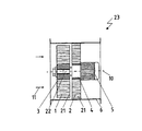
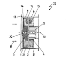
図1は、羽根車1、案内車2、及び大抵は電動モータとして構成されている駆動モータ5の軸に羽根車1を固定するための羽根車ハブ3を有する軸流通風機23を示す。案内翼は、流動を適当な方法で転向するというその機能以外に、駆動モータ5をハウジング6内に保持するという課題を有する。強度及び組立ての理由から、案内車2は、内部を案内車ハブ4によって制限される。駆動モータの軸は、22で指示されている。
本発明によれば、捩じれた成形個別翼を有する通常の羽根車及び案内車の代わりに、特に微細に構造化された材料から成る固体マトリックスから成る羽根車及び案内車が使用される。この場合、セグメントを構成する材料の肉厚は、非常に小さく選択することができる。従って、従来の通風機における流動に対する翼の力作用は、多数の小セグメント又はマトリックスの「構造体要素」に分割される。構造体は、羽根車及び案内車1,2の非常に高い強度を生じさせる。特別な要求がある場合、羽根車及び案内車1,2に、図示されてない支持要素が統合される。
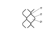
セグメントは、流動方向11に多角形の横断面、蜂の巣状の横断面15又は正方形又は台形の横断面を備える。
FIG. 1 shows an
According to the invention, instead of the usual impeller and guide wheel with twisted molded individual blades, an impeller and guide wheel made of a solid matrix made of a particularly finely structured material is used. In this case, the thickness of the material constituting the segment can be selected very small. Thus, the force action of the wings on the flow in conventional ventilators is divided into a number of small segments or matrix “structural elements”. The structure gives rise to very high strength of the impeller and guide
The segment has a polygonal cross section in the
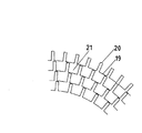
セグメントは、合成物質又は金属から成るバンド19によって形成される。全ての支柱、ウェブ、保持装置等は、同様に構造化された材料から成るか、この材料に統合されるべきである。更に、流体の供給流11の方向と、駆動モータ5のモータ軸及び羽根車1の回転軸10が図示されている。
The segment is formed by a
本発明の好ましい選択的な形態によれば、羽根車及び案内車1,2は、回転もしくは流動音を軽減するために等方の発泡材から形成される。
等方の発泡材は、有利なことに金属又は合成物質の発泡材として構成される。
According to a preferred alternative form of the invention, the impeller and guide
The isotropic foam is advantageously constructed as a foam of metal or synthetic material.
繊維状の構造体14から成る羽根車及び案内車1,2の形成は、同様に有利である。
The formation of the impellers and the
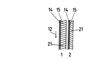
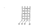
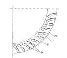
図2には、流動方向11に軸流通風機を見た部分図が拡大されて図示されている。セグメントから成る構造体は、例えば予め製造されたウェブ20とのバンド19の展開及び結合をすることによって生じる。構造体の分割は、旋回運動変化が激しい場合、損失低減の理由から周方向よりも半径方向の方が大抵大きい。何故なら、2次流動の損失は、転向及びセルの側面特性によって半径方向及び周方向に増大するからである。この場合、構造体は、半径方向及び周方向に流出口を備え、これは、半径方向及び周方向の速度及び圧力のバランスのために利用される。
FIG. 2 shows an enlarged partial view of the axial flow fan in the
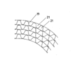
図3は、同軸断面図及びその一平面における展開図である。羽根車及び案内車1,2のために区別される流通路21が認められる。断面の幾何学形状を図説するために流動方向11及び羽根車1の回転方向12が記載されている。流通路21は、図示されているように、一貫していても、複数の部分から成っていてもよい。流通路21の寸法は、層流限界層が、レイノルズ数において乱流限界層への転換の直ぐ下に調節されるように選択すべきである。
FIG. 3 is a coaxial sectional view and a development view in one plane. A
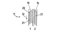
図4は、吸入ノズルを有する軸流通風機を示す。良好な部分負荷特性を得るため、本発明のこの有利な形態によれば、異なった2つの構造体の層が羽根車1において適用される。同じことが、案内車2の場合でも可能である。供給流方向11に第1の層は、繊維状の等方の構造体14を車流入口での衝突損失を最小化するために備える。接続する車流出口での第2の層は、蜂の巣状の構造体15から構成され、摩擦損失を低下させるために有利である。
加えて、繊維状の等方の構造体14は、半径方向の流動バランスを可能にする。羽根車及び案内車1,2の構造体における遠心的及び求心的な通路案内部は、有利なことに所望の半径方向の圧力及び速度の分布を得るために利用することができる。吸入ノズル13は、微細に構造化された羽根車1を鑑み、非常に小さな丸み付け半径を有する。羽根車1の強度を確保するために、異なった層をも相並んで保持するカバーバンド7が使用される。
FIG. 4 shows an axial flow fan having a suction nozzle. In order to obtain good partial load characteristics, according to this advantageous form of the invention, two different layers of structure are applied in the
In addition, the fibrous
図5は、図3に類似した展開同軸断面図に、羽根車及び案内車の流入口における繊維状の等方の構造体14と、羽根車及び案内車1,2の流出口における蜂の巣状の構造体15とを示す。
FIG. 5 is a developed coaxial cross-sectional view similar to FIG. 3, and shows a fibrous
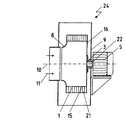
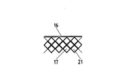
図6には、微細に構造化された材料から成る本発明による羽根車1を有する半径流通風機24を経る軸方向断面が図示されている。微細に構造化された蜂の巣状の材料から成る羽根車1は、サポートディスク16及び羽根車ハブ3を介して駆動モータ5と結合されている。
FIG. 6 shows an axial section through a
カバーディスク8は、羽根車をサポートディスク16に向かい合って位置する側で制限する。羽根車は、渦形室9によって包囲される。異なった適用にあっては、半径流の羽根車1の後方に、同様に微細に構造化された材料から形成されている図示されてない案内車2を使用することが有利である。
The cover disk 8 restricts the impeller on the side facing the
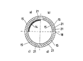
羽根車1は、課題提起に応じて、異なった繊維状の構造体14又は異なった蜂の巣状のセル状の構造体15によって構成される。図7は、半径流通風機の羽根車1を経る半径方向断面の4つの四分円に、異なった組合せ及び構造体を示し、この構造体は、真直ぐな又は曲げられた蜂の巣状の1つ又は複数の構造体、及び組み合わされた繊維及び蜂の巣状の構造体から構成される。一般的に、軸方向及び周方向に羽根車を分割することによって、獲得に努められた微細な構造体が生じる。
図7のa)による第1の四分円には、2層の羽根車が示される。この羽根車は、繊維状の構造体14を有する第1の層と、蜂の巣状の構造体15を有する第2の層とから成る。
図7のb)による第2の四分円には、2つの層が図示されており、その際、第1の層は、半径方向の流動方向に、斜めに配設されたセグメントを有する蜂の巣状の構造体15から、また引き続き第2の層は、半径方向に配設されたセグメントを有する蜂の巣状の構造体から成る。
図7のc)による第4の四分円には、斜めに配設されたセグメントを有する蜂の巣状の構造体15から成る1つの層が図示されている。
図7のd)による第3の四分円には、更にまた、曲げられて配設されたセグメントを有する蜂の巣状の構造体15から成る1つの層が図示されている。
The
In the first quadrant according to FIG. 7a), two layers of impellers are shown. The impeller includes a first layer having a
The second quadrant according to FIG. 7b) shows two layers, the first layer being a honeycomb with segments arranged obliquely in the radial flow direction. The second layer consists of a honeycomb-like structure with segments arranged in the radial direction, and subsequently the second layer.
The fourth quadrant according to c) of FIG. 7 shows a layer consisting of a honeycomb-
The third quadrant according to d) of FIG. 7 also shows a layer of a honeycomb-
図8及び図9には、成形されかつ予め製造された図7によるリブを有する多数の薄いディスク17から成る微細に構造化された半径流羽根車の形成が図示されている。これらのディスクは、軸方向に相並んでセットされかつ互いに結合される。これにより、高い強度を有する半径流の羽根車1が生じ、この強度は、付加的な軸方向のステイによって更に改善することができる。
FIGS. 8 and 9 illustrate the formation of a finely structured radial flow impeller consisting of a number of
図10は、セル状の構造体がリブ付けされた多数のディスク17によって構成される半径流通風機24の羽根車及び案内車1,2を経る展開同軸断面図を示す。セル状の構造体は、サポートディスク16によって制限される。本発明のこの有利な実施形によれば、セグメントの示された配設は、機械的な安定化に通じる。何故なら、そのように配設されたセグメントの周方向の力を、より良好に吸収することができるからである。
FIG. 10 shows a developed coaxial sectional view through the impeller and the
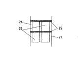
図11a及び11bは、流通路21がバンドからの打抜き及び折曲げによって生じる折り返し26によって構成される軸流の羽根車又は案内車の同軸断面図及び軸方向断面図を示す。半径方向の流動バランスを低減するために、シール部25が使用される。
FIGS. 11a and 11b show coaxial and axial cross-sections of an axial impeller or guide wheel in which the
図12は、そのリブが周方向に対して異なった傾斜を有する2列の折り返し26から構成されるディスクを示す。2列より多くの折り返し26の使用は、本発明の有利な形成である。
FIG. 12 shows a disk composed of two rows of
1 羽根車
2 案内車
3 羽根車ハブ
4 案内車ハブ
5 駆動モータ
6 ハウジング
7 カバーバンド
8 カバーディスク
9 渦形室
10 回転軸
11 供給流
12 羽根車の回転方向
13 吸入ノズル
14 繊維状の構造体
15 蜂の巣状の構造体
16 サポートディスク
17 整形ディスク
18 同軸断面
19 バンド
20 ウェブ
21 流通路
22 駆動モータの軸
23 軸流通風機
24 半径流通風機
25 シール部
26 折り返し
DESCRIPTION OF
Claims (14)
羽根車及び案内車(1,2)が、多数の流通路(21)を有する固体マトリックスから成ること、また固体マトリックスが、不等方に互いに間隔を置いたセグメントから構成されており、これらのセグメントによって、流体のための流通路(21)が構成されること、そして羽根車及び案内車(1,2)が、付加的に整流器又は篩として作用することを特徴とする羽根車及び案内車。 In impellers and guide wheels for fluid machinery, in particular for compressors and ventilators,
The impeller and guide wheel (1, 2) consist of a solid matrix with a number of flow passages (21), and the solid matrix consists of segments spaced from one another in an anisotropic manner, Impeller and guide wheel characterized in that the flow path (21) for the fluid is constituted by the segments and that the impeller and guide wheel (1, 2) additionally act as a rectifier or sieve .
羽根車及び案内車(1,2)が、多数の流通路(21)を有する固体マトリックスから成ること、また固体マトリックスが、等方の多孔質の材料から成り、これらの材料が、流体のための流通路(21)を備えること、そして羽根車及び案内車(1,2)が、付加的に整流器又は篩として作用することを特徴とする羽根車及び案内車。 In impellers and guide wheels for fluid machinery, in particular for compressors and ventilators,
The impeller and guide wheel (1, 2) consist of a solid matrix with a number of flow passages (21), and the solid matrix consists of an isotropic porous material, which is used for fluids And an impeller and guide wheel in which the impeller and guide wheel (1, 2) additionally act as a rectifier or sieve.
羽根車及び案内車(1,2)が、多数の流通路(21)を有する固体マトリックスから成ること、また固体マトリックスが、繊維状の構造体(14)から構成され、これらの構造体が、流体のための流通路(21)を備えること、そして羽根車及び案内車(1,2)が、付加的に整流器又は篩として作用することを特徴とする羽根車及び案内車。 In impellers and guide wheels for fluid machinery, in particular for compressors and ventilators,
The impeller and guide wheel (1, 2) consist of a solid matrix having a number of flow passages (21), and the solid matrix is composed of a fibrous structure (14), Impeller and guide wheel, characterized in that it comprises a flow passage (21) for fluid and that the impeller and guide wheel (1, 2) additionally act as a rectifier or sieve.
羽根車及び案内車(1,2)が、多数の流通路(21)を有する固体マトリックスから成ること、また固体マトリックスが、流動方向(11)に対して横断方向に配設された篩から構成されること、そして羽根車及び案内車(1,2)が、付加的に整流器又は篩として作用することを特徴とする羽根車及び案内車。 In impellers and guide wheels for fluid machinery, in particular for compressors and ventilators,
The impeller and guide wheel (1, 2) consist of a solid matrix with a number of flow passages (21), and the solid matrix consists of a sieve arranged transverse to the flow direction (11) And the impeller and guide wheel (1, 2) additionally act as a rectifier or sieve.
羽根車及び案内車(1,2)が、多数の流通路(21)を有する固体マトリックスから成ること、そして固体マトリックスが、流動方向(11)に少なくとも2つの層から構成されており、その際、第1の層が、繊維状の構造体(14)又は等方の多孔質の材料から構成されており、第2の層が、セグメントから構成されることを特徴とする羽根車及び案内車。 In impellers and guide wheels for fluid machinery, in particular for compressors and ventilators,
The impeller and guide wheel (1, 2) consist of a solid matrix with a number of flow passages (21), and the solid matrix consists of at least two layers in the flow direction (11), The impeller and the guide wheel, wherein the first layer is composed of a fibrous structure (14) or an isotropic porous material, and the second layer is composed of segments. .
The impeller and guide wheel according to claim 1, characterized in that the flow passages (21) are partially connected to one another in the radial direction.
Applications Claiming Priority (1)
| Application Number | Priority Date | Filing Date | Title |
|---|---|---|---|
| DE10302773A DE10302773B3 (en) | 2003-01-17 | 2003-01-17 | Impeller and idler wheels for flow machines, especially compressors and fans, are made from solid matrix with flow channels in which deflection of flow and associated pressure increase take place |
Publications (1)
| Publication Number | Publication Date |
|---|---|
| JP2005290987A true JP2005290987A (en) | 2005-10-20 |
Family
ID=31502579
Family Applications (1)
| Application Number | Title | Priority Date | Filing Date |
|---|---|---|---|
| JP2004005441A Pending JP2005290987A (en) | 2003-01-17 | 2004-01-13 | Impellers and guide wheels for fluid machinery, in particular for compressors and ventilators |
Country Status (5)
| Country | Link |
|---|---|
| US (1) | US20040184914A1 (en) |
| EP (1) | EP1447568B1 (en) |
| JP (1) | JP2005290987A (en) |
| AT (1) | ATE425367T1 (en) |
| DE (2) | DE10302773B3 (en) |
Cited By (6)
| Publication number | Priority date | Publication date | Assignee | Title |
|---|---|---|---|---|
| JP2007100637A (en) * | 2005-10-06 | 2007-04-19 | Matsushita Electric Ind Co Ltd | Blower |
| WO2011114716A1 (en) * | 2010-03-17 | 2011-09-22 | 東京電力株式会社 | Axial flow compressor |
| JP2015500940A (en) * | 2011-12-07 | 2015-01-08 | インテル・コーポレーション | Volume resistance blower device and system |
| US10545546B2 (en) | 2018-02-23 | 2020-01-28 | Intel Corporation | Reversible direction thermal cooling system |
| US11118598B2 (en) | 2018-09-27 | 2021-09-14 | Intel Corporation | Volumetric resistance blowers |
| JP2024536417A (en) * | 2021-10-06 | 2024-10-04 | ティ. ティルナブッカラス, | Inducer-assisted mixed flow ceiling fan |
Families Citing this family (12)
| Publication number | Priority date | Publication date | Assignee | Title |
|---|---|---|---|---|
| DE102005044470A1 (en) * | 2005-09-16 | 2007-03-22 | Orbiter Group Beteiligungs Gmbh | Use of a metal foam in turbomachines, especially in turbines, fans and pumps |
| US7455504B2 (en) * | 2005-11-23 | 2008-11-25 | Hill Engineering | High efficiency fluid movers |
| US20070140842A1 (en) * | 2005-11-23 | 2007-06-21 | Hill Charles C | High efficiency fluid movers |
| US20070177349A1 (en) * | 2005-11-23 | 2007-08-02 | Himanshu Pokharna | High efficiency fluid mover |
| GB0613012D0 (en) * | 2006-06-30 | 2006-08-09 | Qinetiq Ltd | Axial flow impeller |
| GB0612993D0 (en) * | 2006-06-30 | 2006-08-09 | Qinetiq Ltd | Centrifugal impeller |
| NZ597256A (en) | 2009-08-11 | 2013-11-29 | Resmed Motor Technologies Inc | Single stage, axial symmetric blower and portable ventilator |
| US9239060B2 (en) * | 2012-09-28 | 2016-01-19 | Intel Corporation | Blower assembly for electronic device |
| JP7035617B2 (en) | 2018-02-26 | 2022-03-15 | 日本電産株式会社 | Centrifugal fan |
| DE102019212325A1 (en) * | 2019-08-17 | 2021-02-18 | Ziehl-Abegg Se | Method for the quantitative determination of a current operating state-dependent variable of a fan, in particular a pressure change or pressure increase, and fan |
| CN112983852B (en) * | 2021-03-22 | 2022-05-31 | 联想(北京)有限公司 | Fan blade, fan assembly, electronic equipment and manufacturing method of fan assembly |
| GB2632267A (en) * | 2023-07-28 | 2025-02-05 | Dyson Technology Ltd | Diffuser component |
Family Cites Families (10)
| Publication number | Priority date | Publication date | Assignee | Title |
|---|---|---|---|---|
| DE174180C (en) * | ||||
| DE1225808B (en) * | 1960-06-02 | 1966-09-29 | Junker & Ruh Ges Mit Beschraen | Runner for centrifugal blower, which consists of a body traversed by narrow channels in the conveying direction |
| GB2065773A (en) * | 1979-12-21 | 1981-07-01 | Rolls Royce | Rotary Pumps |
| JPH03237298A (en) * | 1990-02-09 | 1991-10-23 | Matsushita Electric Ind Co Ltd | Blower impeller and its manufacturing method |
| US5265348A (en) * | 1992-08-12 | 1993-11-30 | Fleishman Roc V | Porous rotor |
| US5244349A (en) * | 1992-09-24 | 1993-09-14 | Wang Sui Mu | Air fan with lightly-constructed reinforcing fan blades |
| US5584656A (en) * | 1995-06-28 | 1996-12-17 | The Scott Fetzer Company | Flexible impeller for a vacuum cleaner |
| DE19545977A1 (en) * | 1995-12-09 | 1997-06-12 | Fluck Hans Joachim Dr Dipl Ing | Ventilator rotor manufacture for turbo machines |
| JP3656021B2 (en) * | 2000-09-11 | 2005-06-02 | 松下エコシステムズ株式会社 | Centrifugal blower impeller |
| JP2002213391A (en) * | 2001-01-15 | 2002-07-31 | Matsushita Seiko Co Ltd | Centrifugal impeller |
-
2003
- 2003-01-17 DE DE10302773A patent/DE10302773B3/en not_active Expired - Fee Related
-
2004
- 2004-01-07 DE DE502004009108T patent/DE502004009108D1/en not_active Expired - Lifetime
- 2004-01-07 EP EP04000093A patent/EP1447568B1/en not_active Expired - Lifetime
- 2004-01-07 AT AT04000093T patent/ATE425367T1/en not_active IP Right Cessation
- 2004-01-13 JP JP2004005441A patent/JP2005290987A/en active Pending
- 2004-01-20 US US10/760,834 patent/US20040184914A1/en not_active Abandoned
Cited By (10)
| Publication number | Priority date | Publication date | Assignee | Title |
|---|---|---|---|---|
| JP2007100637A (en) * | 2005-10-06 | 2007-04-19 | Matsushita Electric Ind Co Ltd | Blower |
| WO2011114716A1 (en) * | 2010-03-17 | 2011-09-22 | 東京電力株式会社 | Axial flow compressor |
| JP2011196189A (en) * | 2010-03-17 | 2011-10-06 | Tokyo Electric Power Co Inc:The | Axial flow compressor |
| US9206818B2 (en) | 2010-03-17 | 2015-12-08 | Tokyo Electric Power Company, Incorporated | Axial flow compressor |
| JP2015500940A (en) * | 2011-12-07 | 2015-01-08 | インテル・コーポレーション | Volume resistance blower device and system |
| US10545546B2 (en) | 2018-02-23 | 2020-01-28 | Intel Corporation | Reversible direction thermal cooling system |
| US11118598B2 (en) | 2018-09-27 | 2021-09-14 | Intel Corporation | Volumetric resistance blowers |
| US11732727B2 (en) | 2018-09-27 | 2023-08-22 | Intel Corporation | Volumetric resistance blowers |
| JP2024536417A (en) * | 2021-10-06 | 2024-10-04 | ティ. ティルナブッカラス, | Inducer-assisted mixed flow ceiling fan |
| JP7670935B2 (en) | 2021-10-06 | 2025-04-30 | ティ. ティルナブッカラス, | Inducer-assisted mixed flow ceiling fan |
Also Published As
| Publication number | Publication date |
|---|---|
| DE10302773B3 (en) | 2004-03-11 |
| EP1447568B1 (en) | 2009-03-11 |
| DE502004009108D1 (en) | 2009-04-23 |
| EP1447568A2 (en) | 2004-08-18 |
| EP1447568A3 (en) | 2005-10-26 |
| ATE425367T1 (en) | 2009-03-15 |
| US20040184914A1 (en) | 2004-09-23 |
Similar Documents
| Publication | Publication Date | Title |
|---|---|---|
| JP2005290987A (en) | Impellers and guide wheels for fluid machinery, in particular for compressors and ventilators | |
| JP5608062B2 (en) | Centrifugal turbomachine | |
| JP3110205B2 (en) | Centrifugal compressor and diffuser with blades | |
| JP2011021491A (en) | Impeller and rotating machine | |
| JP3507758B2 (en) | Multi-wing fan | |
| JP2011179499A (en) | Impeller for use in centrifugal blower or diagonal flow blower | |
| JP2012072735A (en) | Centrifugal compressor | |
| WO2014115417A1 (en) | Centrifugal rotation machine | |
| US12480515B2 (en) | Compressor | |
| US12480516B2 (en) | Compressor | |
| WO2015053051A1 (en) | Impeller and rotary machine provided with same | |
| WO2008075467A1 (en) | Cascade of axial compressor | |
| US7604458B2 (en) | Axial flow pump and diagonal flow pump | |
| WO2008001032A1 (en) | Axial flow impeller | |
| JP2009133267A (en) | Impeller of compressor | |
| CN102418565A (en) | Low-pressure steam turbine and method of operating the same | |
| JP2023510519A (en) | Fan support module and fan with this fan support module | |
| JP2005016315A (en) | Centrifugal fan and its application | |
| JP2014152637A (en) | Centrifugal compressor | |
| JP2012107619A (en) | Exhaust hood diffuser | |
| KR20030016175A (en) | Vortex flow fan | |
| JP2018141451A (en) | Turbine and gas turbine | |
| WO2003002874A1 (en) | Impeller for multiblade blower, and multiblade blower having the same | |
| JP3575164B2 (en) | Axial fan and air separator used for it | |
| JP4146371B2 (en) | Centrifugal compressor |
Legal Events
| Date | Code | Title | Description |
|---|---|---|---|
| A977 | Report on retrieval |
Free format text: JAPANESE INTERMEDIATE CODE: A971007 Effective date: 20070905 |
|
| A131 | Notification of reasons for refusal |
Free format text: JAPANESE INTERMEDIATE CODE: A131 Effective date: 20071002 |
|
| A601 | Written request for extension of time |
Free format text: JAPANESE INTERMEDIATE CODE: A601 Effective date: 20071227 |
|
| A602 | Written permission of extension of time |
Free format text: JAPANESE INTERMEDIATE CODE: A602 Effective date: 20080107 |
|
| A601 | Written request for extension of time |
Free format text: JAPANESE INTERMEDIATE CODE: A601 Effective date: 20080201 |
|
| A602 | Written permission of extension of time |
Free format text: JAPANESE INTERMEDIATE CODE: A602 Effective date: 20080206 |
|
| A521 | Request for written amendment filed |
Free format text: JAPANESE INTERMEDIATE CODE: A523 Effective date: 20080225 |
|
| A02 | Decision of refusal |
Free format text: JAPANESE INTERMEDIATE CODE: A02 Effective date: 20080408 |
|
| A521 | Request for written amendment filed |
Free format text: JAPANESE INTERMEDIATE CODE: A523 Effective date: 20080804 |
|
| A911 | Transfer to examiner for re-examination before appeal (zenchi) |
Free format text: JAPANESE INTERMEDIATE CODE: A911 Effective date: 20080807 |
|
| A912 | Re-examination (zenchi) completed and case transferred to appeal board |
Free format text: JAPANESE INTERMEDIATE CODE: A912 Effective date: 20080919 |
|
| RD04 | Notification of resignation of power of attorney |
Free format text: JAPANESE INTERMEDIATE CODE: A7424 Effective date: 20100527 |