JP2005290976A - Fixing method for building material and tile unit - Google Patents
Fixing method for building material and tile unit Download PDFInfo
- Publication number
- JP2005290976A JP2005290976A JP2005070577A JP2005070577A JP2005290976A JP 2005290976 A JP2005290976 A JP 2005290976A JP 2005070577 A JP2005070577 A JP 2005070577A JP 2005070577 A JP2005070577 A JP 2005070577A JP 2005290976 A JP2005290976 A JP 2005290976A
- Authority
- JP
- Japan
- Prior art keywords
- net
- adhesive
- adhesive layer
- tile unit
- tile
- Prior art date
- Legal status (The legal status is an assumption and is not a legal conclusion. Google has not performed a legal analysis and makes no representation as to the accuracy of the status listed.)
- Pending
Links
- 239000004566 building material Substances 0.000 title claims abstract description 14
- 238000000034 method Methods 0.000 title claims description 26
- 239000012790 adhesive layer Substances 0.000 claims abstract description 29
- 239000000463 material Substances 0.000 claims abstract description 25
- 239000000853 adhesive Substances 0.000 claims description 49
- 230000001070 adhesive effect Effects 0.000 claims description 47
- 238000000576 coating method Methods 0.000 claims description 11
- 239000000758 substrate Substances 0.000 claims description 9
- 239000011248 coating agent Substances 0.000 claims description 7
- 230000001788 irregular Effects 0.000 abstract description 4
- 239000011230 binding agent Substances 0.000 description 5
- 229920005989 resin Polymers 0.000 description 5
- 239000011347 resin Substances 0.000 description 5
- VTYYLEPIZMXCLO-UHFFFAOYSA-L Calcium carbonate Chemical compound [Ca+2].[O-]C([O-])=O VTYYLEPIZMXCLO-UHFFFAOYSA-L 0.000 description 4
- 238000010276 construction Methods 0.000 description 4
- 239000011521 glass Substances 0.000 description 4
- VYPSYNLAJGMNEJ-UHFFFAOYSA-N Silicium dioxide Chemical compound O=[Si]=O VYPSYNLAJGMNEJ-UHFFFAOYSA-N 0.000 description 3
- NIXOWILDQLNWCW-UHFFFAOYSA-N acrylic acid group Chemical group C(C=C)(=O)O NIXOWILDQLNWCW-UHFFFAOYSA-N 0.000 description 3
- 230000000694 effects Effects 0.000 description 3
- 108010084652 homeobox protein PITX1 Proteins 0.000 description 3
- 239000002245 particle Substances 0.000 description 3
- -1 polypropylene Polymers 0.000 description 3
- 239000000843 powder Substances 0.000 description 3
- 239000004593 Epoxy Substances 0.000 description 2
- GWEVSGVZZGPLCZ-UHFFFAOYSA-N Titan oxide Chemical compound O=[Ti]=O GWEVSGVZZGPLCZ-UHFFFAOYSA-N 0.000 description 2
- XLOMVQKBTHCTTD-UHFFFAOYSA-N Zinc monoxide Chemical compound [Zn]=O XLOMVQKBTHCTTD-UHFFFAOYSA-N 0.000 description 2
- 238000004873 anchoring Methods 0.000 description 2
- 230000000844 anti-bacterial effect Effects 0.000 description 2
- 230000015572 biosynthetic process Effects 0.000 description 2
- 229910000019 calcium carbonate Inorganic materials 0.000 description 2
- 239000000919 ceramic Substances 0.000 description 2
- 238000004140 cleaning Methods 0.000 description 2
- 238000010586 diagram Methods 0.000 description 2
- 238000006073 displacement reaction Methods 0.000 description 2
- 239000010881 fly ash Substances 0.000 description 2
- 239000010954 inorganic particle Substances 0.000 description 2
- ZLNQQNXFFQJAID-UHFFFAOYSA-L magnesium carbonate Chemical compound [Mg+2].[O-]C([O-])=O ZLNQQNXFFQJAID-UHFFFAOYSA-L 0.000 description 2
- 239000001095 magnesium carbonate Substances 0.000 description 2
- 229910000021 magnesium carbonate Inorganic materials 0.000 description 2
- 239000000395 magnesium oxide Substances 0.000 description 2
- CPLXHLVBOLITMK-UHFFFAOYSA-N magnesium oxide Inorganic materials [Mg]=O CPLXHLVBOLITMK-UHFFFAOYSA-N 0.000 description 2
- AXZKOIWUVFPNLO-UHFFFAOYSA-N magnesium;oxygen(2-) Chemical compound [O-2].[Mg+2] AXZKOIWUVFPNLO-UHFFFAOYSA-N 0.000 description 2
- 239000004570 mortar (masonry) Substances 0.000 description 2
- 229920001296 polysiloxane Polymers 0.000 description 2
- 239000004925 Acrylic resin Substances 0.000 description 1
- 229920000178 Acrylic resin Polymers 0.000 description 1
- 239000005995 Aluminium silicate Substances 0.000 description 1
- OYPRJOBELJOOCE-UHFFFAOYSA-N Calcium Chemical compound [Ca] OYPRJOBELJOOCE-UHFFFAOYSA-N 0.000 description 1
- OKTJSMMVPCPJKN-UHFFFAOYSA-N Carbon Chemical compound [C] OKTJSMMVPCPJKN-UHFFFAOYSA-N 0.000 description 1
- 229920000742 Cotton Polymers 0.000 description 1
- JOYRKODLDBILNP-UHFFFAOYSA-N Ethyl urethane Chemical compound CCOC(N)=O JOYRKODLDBILNP-UHFFFAOYSA-N 0.000 description 1
- 239000005909 Kieselgur Substances 0.000 description 1
- 239000004640 Melamine resin Substances 0.000 description 1
- 229920000877 Melamine resin Polymers 0.000 description 1
- 239000004677 Nylon Substances 0.000 description 1
- 239000004698 Polyethylene Substances 0.000 description 1
- 239000004743 Polypropylene Substances 0.000 description 1
- 229920002978 Vinylon Polymers 0.000 description 1
- YKTSYUJCYHOUJP-UHFFFAOYSA-N [O--].[Al+3].[Al+3].[O-][Si]([O-])([O-])[O-] Chemical compound [O--].[Al+3].[Al+3].[O-][Si]([O-])([O-])[O-] YKTSYUJCYHOUJP-UHFFFAOYSA-N 0.000 description 1
- 235000012211 aluminium silicate Nutrition 0.000 description 1
- 239000004760 aramid Substances 0.000 description 1
- 229920003235 aromatic polyamide Polymers 0.000 description 1
- 239000000440 bentonite Substances 0.000 description 1
- 229910000278 bentonite Inorganic materials 0.000 description 1
- SVPXDRXYRYOSEX-UHFFFAOYSA-N bentoquatam Chemical compound O.O=[Si]=O.O=[Al]O[Al]=O SVPXDRXYRYOSEX-UHFFFAOYSA-N 0.000 description 1
- DQXBYHZEEUGOBF-UHFFFAOYSA-N but-3-enoic acid;ethene Chemical compound C=C.OC(=O)CC=C DQXBYHZEEUGOBF-UHFFFAOYSA-N 0.000 description 1
- 239000011575 calcium Substances 0.000 description 1
- 229910052791 calcium Inorganic materials 0.000 description 1
- BRPQOXSCLDDYGP-UHFFFAOYSA-N calcium oxide Chemical compound [O-2].[Ca+2] BRPQOXSCLDDYGP-UHFFFAOYSA-N 0.000 description 1
- 239000000292 calcium oxide Substances 0.000 description 1
- ODINCKMPIJJUCX-UHFFFAOYSA-N calcium oxide Inorganic materials [Ca]=O ODINCKMPIJJUCX-UHFFFAOYSA-N 0.000 description 1
- 229910052799 carbon Inorganic materials 0.000 description 1
- 210000003109 clavicle Anatomy 0.000 description 1
- 239000004927 clay Substances 0.000 description 1
- 229910052570 clay Inorganic materials 0.000 description 1
- 239000003086 colorant Substances 0.000 description 1
- 210000001520 comb Anatomy 0.000 description 1
- 238000005336 cracking Methods 0.000 description 1
- KZHJGOXRZJKJNY-UHFFFAOYSA-N dioxosilane;oxo(oxoalumanyloxy)alumane Chemical compound O=[Si]=O.O=[Si]=O.O=[Al]O[Al]=O.O=[Al]O[Al]=O.O=[Al]O[Al]=O KZHJGOXRZJKJNY-UHFFFAOYSA-N 0.000 description 1
- 238000004049 embossing Methods 0.000 description 1
- 239000000839 emulsion Substances 0.000 description 1
- 239000005038 ethylene vinyl acetate Substances 0.000 description 1
- 238000001125 extrusion Methods 0.000 description 1
- 238000011049 filling Methods 0.000 description 1
- 239000003365 glass fiber Substances 0.000 description 1
- 230000005484 gravity Effects 0.000 description 1
- 239000011256 inorganic filler Substances 0.000 description 1
- 229910003475 inorganic filler Inorganic materials 0.000 description 1
- 239000001023 inorganic pigment Substances 0.000 description 1
- NLYAJNPCOHFWQQ-UHFFFAOYSA-N kaolin Chemical compound O.O.O=[Al]O[Si](=O)O[Si](=O)O[Al]=O NLYAJNPCOHFWQQ-UHFFFAOYSA-N 0.000 description 1
- 239000010410 layer Substances 0.000 description 1
- 230000014759 maintenance of location Effects 0.000 description 1
- 238000004519 manufacturing process Methods 0.000 description 1
- 239000010445 mica Substances 0.000 description 1
- 229910052618 mica group Inorganic materials 0.000 description 1
- 238000000465 moulding Methods 0.000 description 1
- 229910052863 mullite Inorganic materials 0.000 description 1
- 229920001778 nylon Polymers 0.000 description 1
- 230000003647 oxidation Effects 0.000 description 1
- 238000007254 oxidation reaction Methods 0.000 description 1
- 230000001699 photocatalysis Effects 0.000 description 1
- 229920001200 poly(ethylene-vinyl acetate) Polymers 0.000 description 1
- 229920000728 polyester Polymers 0.000 description 1
- 229920000573 polyethylene Polymers 0.000 description 1
- 229920001155 polypropylene Polymers 0.000 description 1
- 229920002635 polyurethane Polymers 0.000 description 1
- 239000004814 polyurethane Substances 0.000 description 1
- 238000003825 pressing Methods 0.000 description 1
- 238000009418 renovation Methods 0.000 description 1
- HBMJWWWQQXIZIP-UHFFFAOYSA-N silicon carbide Chemical compound [Si+]#[C-] HBMJWWWQQXIZIP-UHFFFAOYSA-N 0.000 description 1
- 229910010271 silicon carbide Inorganic materials 0.000 description 1
- 239000000377 silicon dioxide Substances 0.000 description 1
- 239000007921 spray Substances 0.000 description 1
- 230000003068 static effect Effects 0.000 description 1
- 239000000454 talc Substances 0.000 description 1
- 229910052623 talc Inorganic materials 0.000 description 1
- XLYOFNOQVPJJNP-UHFFFAOYSA-N water Substances O XLYOFNOQVPJJNP-UHFFFAOYSA-N 0.000 description 1
- 239000011787 zinc oxide Substances 0.000 description 1
Images

Landscapes
- Finishing Walls (AREA)
- Laminated Bodies (AREA)
Abstract
Description
本発明は、ネットに複数のタイルを配列固定したタイルユニットを、接着剤層を介して基材に貼着した建材に関する。また、本発明は、ネットに複数のタイルを配列固定したタイルユニットを、接着剤層を介して基材に貼着する方法に関する。 The present invention relates to a building material in which a tile unit in which a plurality of tiles are arranged and fixed on a net is attached to a base material via an adhesive layer. The present invention also relates to a method of sticking a tile unit in which a plurality of tiles are arranged and fixed on a net to a base material via an adhesive layer.
従来、接着剤層を介してタイルを所定の目地間隔で配列固定する方法が提案されている。 このような方法によれば、建築基材に接着剤を櫛目鏝で塗布、平鏝で平滑にならして均一な厚みの接着剤層を形成後、タイルを1枚1枚押圧して貼着していくものである。(例えば、特許文献1参照。) Conventionally, a method has been proposed in which tiles are arranged and fixed at predetermined joint intervals via an adhesive layer. According to such a method, an adhesive is applied to a building base material with a comb, and flat and smooth to form an adhesive layer with a uniform thickness, and then the tiles are pressed and stuck one by one. It is something to do. (For example, refer to Patent Document 1.)
タイルを1枚1枚貼着していく方法は、工数も多く、タイルの目地間隔を一定に保つためには職人の技量に負うところが大きいという問題があるため、網目ネット上に複数タイルを所定の目地間隔で接着剤を使用して配列固定したタイルユニットを作製し、このタイルユニットのネット取付面側を建築基材上へ接着剤を用いて固定する方法も提案されている。(例えば、特許文献2参照。)
タイルを基材に塗布した接着剤層に貼着する場合、接着剤層の厚みは数mm程度であるため、タイル裏面が接着剤層にほとんど埋設されない。タイル目地部においては、タイルユニット貼着後もネットが接着剤層の上に露出して外観上好ましくないという問題があり、樹脂モルタル等を目地部に塗り込む工程を要する場合があった。また、目地部のネットを目立たせなくするために、タイルユニットの目地間隔を狭くしなければならないといった意匠上の制約があった。 When the tile is attached to the adhesive layer applied to the base material, the thickness of the adhesive layer is about several millimeters, so that the back surface of the tile is hardly embedded in the adhesive layer. In the tile joint part, there is a problem that the net is exposed on the adhesive layer even after the tile unit is stuck, which is not preferable in appearance, and there is a case where a process of applying resin mortar or the like to the joint part is required. Moreover, in order to make the net of the joint portion inconspicuous, there is a design restriction that the joint interval between the tile units must be narrowed.
本発明は上記問題を解決するためになされたもので、本発明の目的は、ネット上に複数のタイルを配列固定されたネット付きタイルユニットを接着剤層を介して基材に固定する際に、目地部のネットを目立たせずに良好な外観を得ることである。 The present invention has been made to solve the above problems, and the object of the present invention is to fix a tile unit with a net, in which a plurality of tiles are arranged and fixed on a net, to a substrate via an adhesive layer. It is to obtain a good appearance without conspicuous the net of the joint part.
上記目的を達成するために、本発明は、ネット上に複数のタイルが所定の目地間隔で配列されたネット付きタイルユニットを、接着剤層を介して基材に固定した建材であって、前記接着剤層には、複数の突起状の凸部からなる模様が形成されていることを特徴とする建材を提供する。 In order to achieve the above object, the present invention is a building material in which a tile unit with a net in which a plurality of tiles are arranged on a net at a predetermined joint interval is fixed to a base material via an adhesive layer, The adhesive layer is provided with a building material characterized in that a pattern composed of a plurality of protrusions is formed.
また本発明では、建築基材上に複数のタイルからなるタイルユニットを固定する方法であって、前記基材上に接着剤を塗布し、接着剤層を形成する工程と、前記接着剤層上に、ネット上に複数のタイルを所定の目地間隔で配列固定されたネット付きタイルユニットを貼着させる工程とを備え、前記接着剤層には、複数の突起状の凸部からなる模様が形成されるように前記塗布を行うにしたことを特徴とする、建築基材上へのタイルユニットの固定方法を提供する。 Further, in the present invention, a method for fixing a tile unit comprising a plurality of tiles on a building base material, the step of applying an adhesive on the base material to form an adhesive layer, and the adhesive layer And a step of attaching a tile unit with a net in which a plurality of tiles are arranged and fixed on a net at a predetermined joint interval, and the adhesive layer is formed with a pattern composed of a plurality of protruding protrusions. A method of fixing a tile unit on a building base material is provided, characterized in that the application is performed as described above.
ここで、「複数の突起状の凸部からなる模様」とは、櫛目鏝で形成されるような複数の凸条が平行に形成された模様を除く、複数の峰を備えた表面の形状であれば良い。複数の凸部の配列には規則性を有しても不規則であっても良い。不規則な凸部とは、ある特定の凸部とその近傍の凸部の配列に規則性を有さない模様であって、例えば、塗布時に接着剤がローラーから引き離される際に形成される、突起状、小波状、などの形状である。また、「形状が消失しない」とは、重力以外の外力を加えない状態で、上記模様が維持されることであり、凸部形状の経時的な変形は「維持される」の範疇に含まれるものとする。 Here, the “pattern consisting of a plurality of protrusions” is a surface shape having a plurality of peaks, excluding a pattern in which a plurality of protrusions such as those formed by combs are formed in parallel. I need it. The arrangement of the plurality of convex portions may be regular or irregular. Irregular protrusion is a pattern that does not have regularity in the arrangement of a certain specific protrusion and the adjacent protrusions, for example, formed when the adhesive is pulled away from the roller during application, It has a shape such as a protrusion or a small wave. Further, “the shape does not disappear” means that the pattern is maintained in a state in which an external force other than gravity is not applied, and the deformation of the convex shape over time is included in the category of “maintained”. Shall.
また、本発明では、前記複数の突起状の凸部の間隔は、前記ネットの一目の大きさよりも小さいことを特徴とする。目の大きさとは、目の形状の中心点を通る直線上における、ネット糸条の中心間距離である。 In the present invention, the interval between the plurality of protruding protrusions is smaller than the size of the net of the net. The size of the eye is the distance between the centers of the net yarns on a straight line passing through the center point of the eye shape.
接着剤層の表面形状を上記模様に形成することによって、タイルユニット貼着後も、目地部に存在するネットの一部は接着剤層の凸部に埋没するので、あるいは、目地部に存在するネットの一部は露出していても、接着剤層の凸部と凸部との間の谷部に露出したネットが存在するので、外観上ネットが目立つことがなくなる。したがってタイルユニットに貼着後に樹脂モルタル等を目地部に塗り込む必要がなく、また、目地間隔の広いタイルユニットを提供することが可能となる。 By forming the surface shape of the adhesive layer in the above pattern, even after the tile unit is pasted, a part of the net existing in the joint part is buried in the convex part of the adhesive layer, or exists in the joint part. Even if a part of the net is exposed, there is an exposed net in the valley between the convex portions of the adhesive layer, so that the net does not stand out in appearance. Therefore, it is not necessary to apply resin mortar or the like to the joint after being attached to the tile unit, and a tile unit having a wide joint interval can be provided.
本発明によれば、ネット付きタイルユニットを貼着後も目地部のネットが外観上目立たないという効果をもたらす。 According to the present invention, there is an effect that the net of the joint portion is not conspicuous in appearance even after the tile unit with a net is attached.
以下に、本発明の具体的な実施形態について、図に基づき説明する。
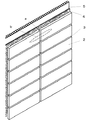
図1は本発明に係る建材の全体構成の概略を示す図である。図2は図1に係る建材の部分断面拡大図である。図2(a)はタイルユニットが接着固定されていない目地部分、すなわち図1のa部分の断面を示した図であり、図2(b)はタイルユニットが接着固定された部分、すなわち図1のb部分の断面を示した図である。
Hereinafter, specific embodiments of the present invention will be described with reference to the drawings.
FIG. 1 is a diagram showing an outline of the overall construction of a building material according to the present invention. FIG. 2 is an enlarged partial cross-sectional view of the building material according to FIG. 2A is a view showing a cross section of a joint portion where the tile unit is not bonded and fixed, that is, a portion of FIG. 1, and FIG. 2B is a portion where the tile unit is bonded and fixed, that is, FIG. It is the figure which showed the cross section of b part.
網目状ネット1上に複数のタイル2が所定の目地間隔で配列固定されたネット付タイルユニットを、接着剤4を介して基材5に固定されている。接着剤4は、基材5とタイル2の裏面との間に2mm以下の厚さで存在している。また、接着剤4は、網目状ネット1を覆うように固定されている。接着剤4の層表面には、多数の凸部が形成されており、相互に隣接する凸部と凸部との間隔はネット一目の大きさよりも小さく形成されている。
A tile unit with a net in which a plurality of
ここで、ネット付タイルユニットは、例えば、所定の目地間隔で配列したタイル上に結着剤を塗布し、その上から網目状ネットを固定することにより得ることができる。また、ネット付きタイルユニットは、予め結着剤を塗布した網目状ネットを、所定の目地間隔で配列したタイル上に固定することによっても得ることができる。 Here, the net-attached tile unit can be obtained, for example, by applying a binder onto tiles arranged at predetermined joint intervals and fixing a mesh net from above. The net-attached tile unit can also be obtained by fixing a mesh net with a binder applied in advance on tiles arranged at predetermined joint intervals.
網目状ネットを形成する糸の太さは、特に限定されないが、0.05〜0.25mmが好ましい。0.05mm以上であることで、網目状ネット1を覆うように固定されたときにネットが効果的にアンカリングの効果をもたらす。また、0.25mm未満、好ましくは0.2mm未満であることで、接着剤厚みを2mm以下に薄くしても充分な量の接着剤がネットを覆うようになり充分な接着剤強度が確保される。なお、網目状ネットを構成する糸が扁平な断面形状である場合は、ネットの厚みが上記範囲となるようにすれば良い。 Although the thickness of the thread | yarn which forms a mesh net is not specifically limited, 0.05-0.25 mm is preferable. By being 0.05 mm or more, when the net-like net 1 is fixed so as to cover the net, the net effectively brings about an anchoring effect. In addition, when the thickness is less than 0.25 mm, preferably less than 0.2 mm, a sufficient amount of adhesive covers the net even if the adhesive thickness is reduced to 2 mm or less, and sufficient adhesive strength is ensured. The In addition, what is necessary is just to make it the thickness of a net | network become the said range, when the thread | yarn which comprises a mesh net | network has a flat cross-sectional shape.
ネットの網目形状は、正方形、三角形、菱形、六角形等いずれであっても良い。また、網目状ネットの目の大きさについては、特に限定されないが、5〜20mmが好ましい。5mm以上であることで、接着剤をタイル裏面に達する接着剤量を充分に確保できる。また、20mm以下、好ましくは15mm以下、より好ましくは10mm未満であることで、ネットが効果的にアンカリングの効果をもたらす。 The mesh shape of the net may be any of square, triangle, rhombus, hexagon and the like. The mesh size of the mesh net is not particularly limited, but is preferably 5 to 20 mm. By being 5 mm or more, it is possible to sufficiently secure the amount of adhesive that reaches the back surface of the tile. Moreover, a net | network brings the effect of anchoring effectively because it is 20 mm or less, Preferably it is 15 mm or less, More preferably, it is less than 10 mm.
網目状ネットの材質は、例えば、ナイロン、ポリエステル、ビニロン、アクリル、ポリプロピレン、ポリエチレン、アラミド、木綿、人絹、ガラス繊維等が好適に利用できる。また、ネット表面には樹脂加工を施しているのが好ましい。この樹脂加工は網目のずれを防止するとともに、配列したタイルに接着する時の加工性が向上する。樹脂は特に限定されないが、例えば、アクリル樹脂、メラミン樹脂等が好適に利用できる。さらに前記樹脂には、タイルユニットを基材に固定するための接着剤と色を合致させるための着色料を添加することも可能である。 As the material of the mesh net, for example, nylon, polyester, vinylon, acrylic, polypropylene, polyethylene, aramid, cotton, human silk, glass fiber and the like can be suitably used. Moreover, it is preferable that resin processing is given to the net surface. This resin processing prevents misalignment of the mesh and improves workability when adhering to the arranged tiles. Although resin is not specifically limited, For example, an acrylic resin, a melamine resin, etc. can be utilized suitably. Furthermore, it is also possible to add a colorant for matching the color to the adhesive for fixing the tile unit to the substrate.
タイルは、陶磁器製、ガラス製のセラミックスからなり、施釉タイルでも無釉タイルでも利用できる。例えば、造粒粉を作成後に金型中で乾式プレス成形し、その上に必要に応じて釉薬を塗布し焼成することで得られる。また、素地にフライアッシュバルーン、シラスバルーン、ガラスバルーンなどの軽量骨材や、炭化珪素などの発泡材を添加した軽量タイルも好適に利用できる。 The tiles are made of ceramics made of ceramic or glass, and can be used with either glazed tiles or plain tiles. For example, the granulated powder can be obtained by dry press molding in a mold after creating the granulated powder, and applying a glaze on the powder as needed and baking it. In addition, lightweight tiles such as fly ash balloons, shirasu balloons, glass balloons, and the like, and lightweight tiles such as silicon carbide added to the substrate can also be suitably used.
タイル裏面は裏足の無いか、裏足高さが1mm未満の形状とする。そうすることで、タイルの裏面の略全体に亘って接着剤が密着することが可能となり、充分な接着強度が確保される。 The tile back has a shape with no back foot or a back foot height of less than 1 mm. By doing so, it becomes possible for an adhesive agent to contact | adhere over substantially the whole back surface of a tile, and sufficient adhesive strength is ensured.
さらに、タイル表面には光触媒層を設けても良い。そうすることで、タイル表面にセルフクリーニング性や抗菌性を付与することができる。また、親水性や抗菌性などの機能性を有する物質をタイル表面に担持あるいは被覆することができる。 Further, a photocatalytic layer may be provided on the tile surface. By doing so, self-cleaning and antibacterial properties can be imparted to the tile surface. Further, a functional material such as hydrophilicity or antibacterial property can be carried or coated on the tile surface.
網目状ネット上への裏足のないタイルの固定には、例えば、水系の結着剤が好適に利用できる。結着剤の種類としては、例えば、エチレン酢酸ビニル、ポリアクリル、ポリウレタン等のエマルジョン結着剤が利用可能である。 For example, a water-based binder can be preferably used for fixing a tile without a back foot on a mesh net. As the kind of the binder, for example, an emulsion binder such as ethylene vinyl acetate, polyacryl, and polyurethane can be used.
タイル間の目地間隔は、1〜20mmが好ましい。1〜5mmでは目地上のネットが目立ちにくく、5〜20mmでは建材におけるタイル使用重量が減少するため、壁基材上への施工が容易になる。 The joint spacing between the tiles is preferably 1 to 20 mm. When it is 1 to 5 mm, the net on the ground is not conspicuous, and when it is 5 to 20 mm, the tile use weight in the building material is reduced, so that the construction on the wall base material becomes easy.
次に、壁等の建築基材へのネット付きタイルユニットの固定方法について説明する。
基材には、清掃、割れやへこみのパテ埋め等の下地調整を適宜施した後、タイルユニットと基材とを接着固定するための接着剤を塗布する。接着剤は、基材とタイルの裏面との間に2mm以下、好ましくは1mm未満の厚さで存在しているようにする。接着剤の厚さは基材への付着量および塗布面積から計算によって求めるものとする。
Next, a method for fixing the tile unit with a net to a building base material such as a wall will be described.
The base material is appropriately subjected to groundwork adjustment such as cleaning, cracking and filling of dents, and then an adhesive for bonding and fixing the tile unit and the base material is applied. The adhesive is present between the substrate and the back of the tile in a thickness of 2 mm or less, preferably less than 1 mm. The thickness of the adhesive is determined by calculation from the amount of adhesion to the substrate and the application area.
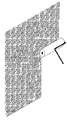
接着剤の塗布は、櫛目鏝を利用したこて塗り、コーキングガンのような連続押し出し装置を使用する方法、ローラーによるロール塗布、スプレー塗布により、所定量の接着剤を塗りつける接着剤塗布工程を行った後、表面に凸部を形成する工程を行う。特に、ローラーを用いたロール塗布は、接着剤塗布および不規則な凸部形成を同時に行うことができ、容易に接着剤を薄く均一に塗布することが可能となるので好ましい。 The adhesive is applied by applying a trowel using a comb, using a continuous extrusion device such as a caulking gun, applying a roll using a roller, and applying an adhesive by applying a spray. Then, the process of forming a convex part on the surface is performed. In particular, roll application using a roller is preferable because adhesive application and irregular projection formation can be performed simultaneously, and the adhesive can be easily applied thinly and uniformly.
図3は、壁基材にローラーを用いたロール塗布法にて接着剤を塗布する工程の概略を示した図である。図示した例では、接着剤を予めローラーに付着させ、基材表面に転写するものである。転写の際に接着剤の一部がその粘性によってローラー側に引き上げられることによって、上述した凸部が形成される。このような形成方法においては、塗装に用いるときに使用される市販のローラーを使用できる。より具体的には、後述する接着剤の適用の際には、スポンジローラー、鎖骨ローラーが好適に利用できる。なお、ここに挙げた例では、接着剤塗布と凸部形成を同時に行ったが、上記の方法で所定量の接着剤を付着させた後に、ローラーで基材に均一にならす際に凸部を形成させても良い。 FIG. 3 is a diagram showing an outline of a process of applying an adhesive by a roll coating method using a roller on a wall substrate. In the illustrated example, an adhesive is attached to a roller in advance and transferred to the surface of the substrate. During transfer, a part of the adhesive is pulled up to the roller side due to its viscosity, whereby the above-described convex portion is formed. In such a forming method, a commercially available roller used for coating can be used. More specifically, a sponge roller and a clavicle roller can be suitably used when applying the adhesive described later. In the example given here, the adhesive application and the convex portion formation were performed at the same time, but after applying a predetermined amount of adhesive by the above method, the convex portion was formed when the roller was evenly applied to the substrate. It may be formed.
凸部を形成するための他の例としては、こて塗り等でほぼ平滑に製膜された接着剤層が硬化する前に、スタンプやローラーによって型押しして凸部を形成する方法を挙げることができる。この方法で使用されるスタンプやローラーの接着剤と接触する面には、凸部の形状に合わせた窪みが形成されている。 As another example of forming the convex portion, there is a method in which the convex portion is formed by embossing with a stamp or a roller before the adhesive layer formed almost smoothly by trowel coating or the like is cured. be able to. On the surface that comes into contact with the stamp or roller adhesive used in this method, a depression is formed in accordance with the shape of the convex portion.
図3に示したロール塗布法の場合、接着剤の粘性を、使用環境下(0〜40℃)において、B型粘度計No.7ローター、回転数10rpmで1000Pa・s以下、好ましい上限値は500Pa・s以下、より好ましくは300Pa・s以下とし、かつ、B型粘度計No.7ローター、回転数1rpmで100Pa・s以上、好ましくは200Pa・s以上の範囲とする。さらに好ましい接着剤の粘性は、BH型粘度計No.7ローター、回転数20rpmで20〜200Pa・sの範囲である。また、好ましいTI値は4以上20未満であり、5以上20未満がより好ましい。TI値とはチクソ指数のことであって、[1rpmでの粘度]/[10rpmでの粘度]にて求める。ローラーで塗布するためには低粘度化することが望ましいが、低粘度化することによって、タイルのズレ抵抗性が問題になるため、上記の範囲とすることで、ロール塗布法で接着剤を塗布することと、鉛直面に接着剤を塗布直後にタイルを接着してもタイルがずれ落ちたり剥離せずに保持することが可能となる。さらに、上記の範囲とすることで、ロール塗布にて容易に凸部を形成することが可能となる。 In the case of the roll coating method shown in FIG. 7 rotor, 1000 Pa · s or less at a rotation speed of 10 rpm, a preferable upper limit value is 500 Pa · s or less, more preferably 300 Pa · s or less. The range is 100 Pa · s or more, preferably 200 Pa · s or more at 7 rotors and 1 rpm. Further preferred adhesive viscosity is BH viscometer No. The range is 20 to 200 Pa · s at 7 rotors and 20 rpm. The preferable TI value is 4 or more and less than 20, and more preferably 5 or more and less than 20. The TI value is the thixo index and is obtained by [viscosity at 1 rpm] / [viscosity at 10 rpm]. In order to apply with a roller, it is desirable to reduce the viscosity. However, by reducing the viscosity, the displacement resistance of the tile becomes a problem. By setting the above range, the adhesive is applied by the roll coating method. It is possible to hold the tile without falling off or peeling even if the tile is bonded to the vertical surface immediately after the adhesive is applied. Furthermore, it becomes possible to form a convex part easily by roll application by setting it as said range.
ロール塗布法において使用される接着剤は、降伏値を200Pa以上とすることにより、塗布直後のタイル保持性、すなわちタイルの剥落やズレに対する抵抗性が特に優れた接着剤を得ることが可能である。降伏値は、23℃におけるコーン・プレート型粘度計により求めた粘度特性から、CASSON式によって算出される。
CASSON式:√S=a√D+b
S:せん断応力 D:せん断速度 a,b:定数
ここで、D=0とすると、
√S=b となり、b二乗が降伏値(S0)となる。
降伏値は非常に低いせん断領域での現象を把握でき、値が高いほど静摩擦が大きいとみなすことができる。
The adhesive used in the roll coating method can obtain an adhesive having particularly excellent resistance to tile retention immediately after coating, that is, tile peeling and displacement, by setting the yield value to 200 Pa or more. . The yield value is calculated by the CASSON equation from the viscosity characteristics obtained with a cone-plate viscometer at 23 ° C.
CASSON formula: √S = a√D + b
S: Shear stress D: Shear rate a, b: Constant where D = 0
√S = b, and b square is the yield value (S0).
The yield value can grasp the phenomenon in a very low shear region, and the higher the value, the greater the static friction.
接着剤には、アクリル系、エポキシ系、ウレタン系、アクリルシリコーン系、エポキシシリコーン系等の有機系接着剤単独あるいは複数組み合わせたものを利用でき、必要に応じて炭酸カルシウム、シリカ、炭酸マグネシウム、酸化カルシウム、酸化マグネシウム、ガラスバルーン、珪藻土、ムライト、カオリン、タルク、クレー、マイカ、ベントナイト、フライアッシュ、ケイ酸アルミニウム、酸化亜鉛等の無機充填剤やチタニア、カーボン等の無機顔料を添加したものを好適に利用できる。これらの材料は特に限定されず、所望の粘性、TI値に応じて公知の材料を適宜選択する。 Adhesives can be organic adhesives such as acrylic, epoxy, urethane, acrylic silicone, and epoxy silicone, or a combination of multiple organic adhesives. If necessary, calcium carbonate, silica, magnesium carbonate, oxidation Suitable with calcium, magnesium oxide, glass balloon, diatomaceous earth, mullite, kaolin, talc, clay, mica, bentonite, fly ash, aluminum silicate, zinc oxide and other inorganic fillers and titania, carbon and other inorganic pigments Available to: These materials are not particularly limited, and known materials are appropriately selected according to desired viscosity and TI value.
ロール塗布によって接着剤層の表面に凸部を形成する際に、接着剤が過剰にローラー側に引き上げられて糸を引くようになる場合がある。このような性質(糸引き性)を抑制し、ローラー抵抗を軽くするためには、粒子径1μm以上1000μm以下、好ましくは10μm以上500μm以下、より好ましくは100μm以上300μm以下の無機粒子を、接着剤の1重量%以上70重量%以下、好ましくは3%以上50重量%以下の範囲で添加する。このような無機粒子としては、炭酸カルシウム、ガラスバルーン、炭酸マグネシウム、酸化カルシウム、酸化マグネシウムを利用できる。
なお、粒子径は走査型電子顕微鏡で観察し、画像処理して平均粒子径を測定した値である。
When forming convex portions on the surface of the adhesive layer by roll application, the adhesive may be excessively pulled up to the roller side to pull the yarn. In order to suppress such properties (thread drawability) and reduce the roller resistance, inorganic particles having a particle diameter of 1 μm to 1000 μm, preferably 10 μm to 500 μm, more preferably 100 μm to 300 μm are used. 1% by weight or more and 70% by weight or less, preferably 3% or more and 50% by weight or less. As such inorganic particles, calcium carbonate, glass balloon, magnesium carbonate, calcium oxide, and magnesium oxide can be used.
The particle diameter is a value obtained by observing with a scanning electron microscope, image processing, and measuring the average particle diameter.
接着剤を塗布し、凸部形成した後に、タイルユニットを押付け固定し、接着剤を硬化させることで、本発明の建材が完成する。タイルユニットを押付けることによって、ネットの目の部分には前記タイルの裏面の略全面に亘って密着するように接着剤が充填されるようになり、基材とその上に固定するタイルとの接着強度を充分に確保することが可能となる。また、目地部においては接着剤層の凸部が保持されつつ、ネットが接着剤層の内部か、凸部と凸部との間の谷に埋設されるため、ネットが外観上目立たなくなるのである。 After the adhesive is applied and the convex portions are formed, the tile unit is pressed and fixed, and the adhesive is cured to complete the building material of the present invention. By pressing the tile unit, the net part of the net is filled with an adhesive so as to adhere to almost the entire back surface of the tile. It becomes possible to ensure sufficient adhesive strength. In addition, in the joint portion, while the convex portion of the adhesive layer is held, the net is embedded in the inside of the adhesive layer or in the valley between the convex portion and the convex portion, so that the net becomes inconspicuous in appearance. .
本発明の方法は、タイル貼り建材の工場生産、建物の壁などの外構物のリフォームや新設現場でのタイル貼り施工に好適に利用できる。
The method of the present invention can be suitably used for factory production of tiled building materials, renovation of external structures such as building walls, and tiled construction at a new construction site.
1…網目状ネット、
2…タイル、
3…目地、
4…接着剤、
5…基材
1 ... Mesh net,
2 ... Tile,
3 ... Joints,
4 ... Adhesive,
5. Base material
Claims (7)
前記接着剤層には、複数の突起状の凸部からなる模様が形成されていることを特徴とする建材。 A building material in which a tile unit with a net in which a plurality of tiles are arranged at predetermined joint intervals on a net is fixed to a base material via an adhesive layer,
The adhesive layer is formed with a pattern composed of a plurality of protruding protrusions.
前記基材上に接着剤を塗布し、接着剤層を形成する工程と、前記接着剤層上に、ネット上に複数のタイルを所定の目地間隔で配列固定されたネット付きタイルユニットを貼着させる工程とを備え、
前記接着剤層には、複数の突起状の凸部からなる模様が形成されるように前記塗布を行うにしたことを特徴とする、建築基材上へのタイルユニットの固定方法。 A method of fixing a tile unit composed of a plurality of tiles on a building substrate,
A step of applying an adhesive on the base material to form an adhesive layer, and a net-attached tile unit in which a plurality of tiles are arranged and fixed on the net at predetermined joint intervals on the adhesive layer. A process of
The method for fixing a tile unit on a building base material, wherein the coating is performed so that a pattern composed of a plurality of protrusions is formed on the adhesive layer.
The method according to claim 3, wherein the shape of the convex portion does not disappear until the adhesive is cured.
Priority Applications (1)
| Application Number | Priority Date | Filing Date | Title |
|---|---|---|---|
| JP2005070577A JP2005290976A (en) | 2004-03-12 | 2005-03-14 | Fixing method for building material and tile unit |
Applications Claiming Priority (2)
| Application Number | Priority Date | Filing Date | Title |
|---|---|---|---|
| JP2004071353 | 2004-03-12 | ||
| JP2005070577A JP2005290976A (en) | 2004-03-12 | 2005-03-14 | Fixing method for building material and tile unit |
Publications (1)
| Publication Number | Publication Date |
|---|---|
| JP2005290976A true JP2005290976A (en) | 2005-10-20 |
Family
ID=35324215
Family Applications (1)
| Application Number | Title | Priority Date | Filing Date |
|---|---|---|---|
| JP2005070577A Pending JP2005290976A (en) | 2004-03-12 | 2005-03-14 | Fixing method for building material and tile unit |
Country Status (1)
| Country | Link |
|---|---|
| JP (1) | JP2005290976A (en) |
Cited By (1)
| Publication number | Priority date | Publication date | Assignee | Title |
|---|---|---|---|---|
| JP2018131811A (en) * | 2017-02-15 | 2018-08-23 | Toto株式会社 | Method for manufacturing tile unit, adhesive coating device, and tile unit manufacturing apparatus |
-
2005
- 2005-03-14 JP JP2005070577A patent/JP2005290976A/en active Pending
Cited By (1)
| Publication number | Priority date | Publication date | Assignee | Title |
|---|---|---|---|---|
| JP2018131811A (en) * | 2017-02-15 | 2018-08-23 | Toto株式会社 | Method for manufacturing tile unit, adhesive coating device, and tile unit manufacturing apparatus |
Similar Documents
| Publication | Publication Date | Title |
|---|---|---|
| CA2530192A1 (en) | Multi-layer covering | |
| JP7179953B2 (en) | Face material | |
| US9562363B2 (en) | Self bonding floor tile | |
| JP3705291B2 (en) | Fixing method for building materials and tile units | |
| JP2005290976A (en) | Fixing method for building material and tile unit | |
| JP2005290975A (en) | Method of fixing tile onto building material and building base material | |
| JP7161540B2 (en) | freeze tape | |
| JP2005290974A (en) | Method of fixing tile onto building base material | |
| JP2006029061A (en) | Building material and tile unit fixing method | |
| CN104675092A (en) | Method for adhering face brick of building | |
| JP2017185487A (en) | Film formation method | |
| JP3685207B1 (en) | Fixing method for building materials and tile units | |
| JP2024026652A (en) | splicing tape | |
| JP2005307590A (en) | Method for laying tile on building base material | |
| CN210887904U (en) | Paving pad | |
| JP2005256488A (en) | Tile unit, method for fixing building material and tile unit | |
| JP2005256487A (en) | Tile unit, building material and method for fixing tile unit | |
| CN207245068U (en) | Plaster technique ceramic tile | |
| JPS63295207A (en) | Joint filling technique for porcelain tile | |
| RU239444U1 (en) | Stencil for applying decorative coating | |
| TW394808B (en) | Method of processing the crevices on the surface of building | |
| JP2007046334A (en) | Decorative panel manufacturing method | |
| CN221778875U (en) | A kind of facing brick anti-air drum paving construction structure | |
| JP2534064B2 (en) | Jointed adhesive sheet and method of using the same | |
| CN216865776U (en) | Building veneer sheet structure |
Legal Events
| Date | Code | Title | Description |
|---|---|---|---|
| RD02 | Notification of acceptance of power of attorney |
Effective date: 20060608 Free format text: JAPANESE INTERMEDIATE CODE: A7422 |
|
| A711 | Notification of change in applicant |
Effective date: 20060704 Free format text: JAPANESE INTERMEDIATE CODE: A711 |
|
| A521 | Written amendment |
Free format text: JAPANESE INTERMEDIATE CODE: A821 Effective date: 20060704 |
|
| A977 | Report on retrieval |
Free format text: JAPANESE INTERMEDIATE CODE: A971007 Effective date: 20070529 |
|
| A131 | Notification of reasons for refusal |
Free format text: JAPANESE INTERMEDIATE CODE: A131 Effective date: 20070605 |
|
| A02 | Decision of refusal |
Effective date: 20071009 Free format text: JAPANESE INTERMEDIATE CODE: A02 |