JP2005290971A - Fireproof panel for tunnel and fireproof structure of tunnel - Google Patents
Fireproof panel for tunnel and fireproof structure of tunnel Download PDFInfo
- Publication number
- JP2005290971A JP2005290971A JP2005061799A JP2005061799A JP2005290971A JP 2005290971 A JP2005290971 A JP 2005290971A JP 2005061799 A JP2005061799 A JP 2005061799A JP 2005061799 A JP2005061799 A JP 2005061799A JP 2005290971 A JP2005290971 A JP 2005290971A
- Authority
- JP
- Japan
- Prior art keywords
- tunnel
- steel plate
- fireproof
- fireproof panel
- thermally expandable
- Prior art date
- Legal status (The legal status is an assumption and is not a legal conclusion. Google has not performed a legal analysis and makes no representation as to the accuracy of the status listed.)
- Pending
Links
Images
Landscapes
- Lining And Supports For Tunnels (AREA)
Abstract
【課題】 保守点検が不可欠なトンネル覆工の目視観察が可能で、かつ、火災時におけるトンネル覆工に対する熱影響を抑える。
【解決手段】
鋼板2と、鋼板2の一面に貼着され、加熱によって膨張して耐火性断熱層を形成する熱膨張性耐火材料シート3と、熱膨張性耐火材料シート3の他面に貼着された薄鋼板4と、から耐火パネル1が構成される。そして、耐火パネル1は、熱膨張性耐火材料シート3が鋼板2および薄鋼板4によって挾持された状態で、周縁部が、軸部に熱可塑性材料製の筒状体7が嵌挿された固定ボルト5およびナット6を介して締結されている。このような耐火パネル1は、空気層S側に固定ボルト5の軸部および熱可塑性材料製の筒状体7が位置するように、耐火パネル1をトンネル覆工に取り付けられる。
【選択図】 図6PROBLEM TO BE SOLVED: To visually observe a tunnel lining in which maintenance inspection is indispensable, and to suppress a thermal influence on the tunnel lining in a fire.
[Solution]
Steel sheet 2, a thermally expandable refractory material sheet 3 that is bonded to one surface of steel sheet 2 and expands by heating to form a refractory heat insulating layer, and a thin film that is bonded to the other surface of thermally expandable refractory material sheet 3 The fireproof panel 1 is composed of the steel plate 4. And the fireproof panel 1 is a state in which the thermally expandable fireproof material sheet 3 is sandwiched between the steel plate 2 and the thin steel plate 4, and the peripheral portion is fixed by inserting the cylindrical body 7 made of thermoplastic material into the shaft portion. Fastened via bolts 5 and nuts 6. Such a refractory panel 1 is attached to the tunnel lining so that the shaft portion of the fixing bolt 5 and the tubular body 7 made of a thermoplastic material are located on the air layer S side.
[Selection] Figure 6
Description
この発明は、主として既設や新設の道路トンネルや鉄道トンネルを構成するトンネル覆工を火災の熱から守るために用いられる耐火パネルおよび耐火パネルを用いたトンネルの耐火構造に関するものである。 The present invention mainly relates to a fireproof panel used for protecting tunnel linings constituting existing and new road tunnels and railway tunnels from the heat of a fire, and a fireproof structure of a tunnel using the fireproof panel.
道路トンネル内での自動車同士の衝突や転倒などによって火災が発生した場合、トンネルを構成するトンネル覆工に高温の熱が作用し、コンクリートに含まれる水分が急速に蒸発するなどにより、コンクリートが爆裂してトンネルが崩壊するおそれがある。また、爆裂に至らない場合でも、コンクリートが劣化して亀裂が入り、火災が鎮火した後にコンクリートの崩落や剥離の危険が生じる。 When a fire occurs due to a collision between cars or falls in a road tunnel, the concrete explodes due to high-temperature heat acting on the tunnel lining that forms the tunnel and the moisture contained in the concrete evaporates rapidly. The tunnel may collapse. Even if the explosion does not occur, the concrete deteriorates and cracks, and after the fire is extinguished, there is a risk of collapse or peeling of the concrete.
このような事態を防止するため、鋼板および鋼板に積層された断熱材からなる耐火パネルを、トンネル内空側に鋼板が位置するように、トンネル覆工の内面に設置し、トンネル覆工を熱から守ることが提案されている(例えば、特許文献1参照)。また、鋼板および鋼板に積層された断熱材からなる耐火パネルの鋼板周辺部を、隣接する耐火パネルの鋼板周辺部と重なり合うように形成して、トンネル内火災が発生した場合に、火災時の熱膨張により隣接する耐火パネルの鋼板の間から断熱材を露出させることなく保護することも知られている(例えば、特許文献2参照)。 In order to prevent such a situation, a fireproof panel made of a steel plate and a heat insulating material laminated on the steel plate is installed on the inner surface of the tunnel lining so that the steel plate is located on the inner side of the tunnel, and the tunnel lining is heated. It has been proposed to protect it (see, for example, Patent Document 1). In addition, when a fire in a tunnel occurs by forming a steel plate periphery of a fireproof panel made of steel plates and a heat insulating material laminated on the steel plate so as to overlap with a steel plate periphery of an adjacent fireproof panel, It is also known that protection is performed without exposing a heat insulating material between steel plates of adjacent fireproof panels by expansion (see, for example, Patent Document 2).
ここで、耐火パネルに用いられる断熱材としては、一般に、珪酸カルシウムボード、グラスウール、ロックウール、セラミックなどが採用される。
しかしながら、前述したトンネルの耐火構造は、トンネルを構成するトンネル覆工の全面を耐火パネルによって覆うものであるから、トンネル覆工のひび割れや漏水状況など、トンネル覆工の保守点検に不可欠な目視観察ができないものとなる。また、断熱性能を確保するためには、断熱材の厚みを大きくする必要があるが、トンネル内空側の建築限界の制約より、既設のトンネルに設置できない場合も発生し得る。特に、漏水の排水などを考慮して耐火パネルとトンネル覆工の内面との間に空間を確保しようとした場合に、影響が顕著となる。 However, since the tunnel fireproof structure described above covers the entire surface of the tunnel lining that constitutes the tunnel with a fireproof panel, visual observation is essential for maintenance and inspection of the tunnel lining, such as cracks in the tunnel lining and water leakage. Can not be. Moreover, in order to ensure the heat insulation performance, it is necessary to increase the thickness of the heat insulating material, but it may occur in some cases because it cannot be installed in an existing tunnel due to the construction limit on the air side inside the tunnel. In particular, the effect becomes significant when an attempt is made to secure a space between the fireproof panel and the inner surface of the tunnel lining in consideration of drainage of water leakage.
本発明は、このような問題点に鑑みてなされたもので、保守点検が不可欠なトンネル覆工の目視観察が可能で、かつ、火災時におけるトンネル覆工に対する熱影響を抑えることのできるトンネル用耐火パネルおよびトンネルの耐火構造を提供するものである。 The present invention has been made in view of such problems, and can be used for visual observation of tunnel lining in which maintenance and inspection are indispensable, and can suppress the thermal influence on the tunnel lining during a fire. It provides fireproof panels and tunnel fireproof structures.
本発明のトンネルの耐火パネルは、トンネルを構成するトンネル覆工の内面に取り付けられる耐火パネルであって、耐火パネルには、離散的に複数個の穴が形成され、トンネル覆工の内面が耐火パネルの穴を通して目視観察可能であることを特徴とするものである。 The fireproof panel of the tunnel of the present invention is a fireproof panel attached to the inner surface of the tunnel lining constituting the tunnel, and the fireproof panel is formed with a plurality of discrete holes, and the inner surface of the tunnel lining is fireproof. It is characterized by being visually observable through a hole in the panel.
本発明によれば、耐火パネルの穴を通してトンネル覆工の内面を目視観察することができる。このため、トンネル覆工の保守点検に際して、コンクリートのひび割れや漏水などを把握することができ、トンネル覆工の異常を早期に発見することが可能となる。 According to the present invention, the inner surface of the tunnel lining can be visually observed through the hole of the fireproof panel. For this reason, it is possible to grasp concrete cracks, water leakage, and the like during maintenance inspection of the tunnel lining, and it is possible to detect abnormalities in the tunnel lining early.
ここで、耐火パネルとしては、耐火性に優れた金属板や断熱材を挙げることができる。 Here, as a fireproof panel, the metal plate and heat insulating material excellent in fire resistance can be mentioned.
本発明において、前記耐火パネルが、複数個の穴を形成した鋼板または断熱材と、鋼板または断熱材の一面に設けられ、加熱によって膨張して耐火性断熱層を形成する熱膨張性耐火材料と、から構成されていると、耐火パネルに穴が形成されたことに伴う耐火パネルの断熱性能の低下を抑えることができる。すなわち、耐火パネルに穴が形成されることにより、断熱性能が低下し、要求する性能を満足できない場合が考えられるが、火災時に熱膨張性耐火材料が熱膨張して耐火性断熱層を形成し、耐火パネルの穴を閉鎖することから、穴が形成されたことによる耐火パネルの断熱性能の低下を抑えることができる。 In the present invention, the fireproof panel is a steel plate or a heat insulating material in which a plurality of holes are formed, and a thermally expandable fire resistant material that is provided on one surface of the steel plate or the heat insulating material and expands by heating to form a fire resistant heat insulating layer. When comprised from, the fall of the heat insulation performance of the fireproof panel accompanying the hole being formed in the fireproof panel can be suppressed. In other words, there may be a case where the hole is formed in the refractory panel, resulting in a decrease in the heat insulation performance and the required performance cannot be satisfied. Since the hole of the fireproof panel is closed, it is possible to suppress a decrease in the heat insulation performance of the fireproof panel due to the formation of the hole.
この場合、熱膨張性耐火材料は、通常は薄い状態で存在するので、耐火パネルの厚みを大きく増加させることはなく、トンネル内空の建築限界に影響を与えることがない。 In this case, since the heat-expandable refractory material usually exists in a thin state, the thickness of the refractory panel is not greatly increased, and the construction limit in the tunnel interior is not affected.
ここで、鋼板としては、鋼板、亜鉛メッキ鋼板、亜鉛−アルミ合金メッキ鋼板、塗装鋼板、塩ビ鋼板、ステンレス鋼板など、耐火性に優れた各種鋼板を挙げることができる。また、断熱材としては、珪酸カルシウムボード、グラスウール、ロックウール、セラミックなどを挙げることができる。 Here, as a steel plate, various steel plates excellent in fire resistance, such as a steel plate, a galvanized steel plate, a zinc-aluminum alloy plated steel plate, a coated steel plate, a vinyl chloride steel plate, and a stainless steel plate, can be mentioned. Examples of the heat insulating material include calcium silicate board, glass wool, rock wool, and ceramic.
また、熱膨張性耐火材料は、菊水化学工業株式会社より商品名「ウエスタ」として市販されており、穴を形成した鋼板または断熱材を熱膨張性耐火材料にディッピングしたり、吹き付け塗装すればよい。 In addition, the heat-expandable refractory material is commercially available from Kikusui Chemical Co., Ltd. under the trade name “Wester”, and a steel plate or a heat insulating material with holes formed may be dipped or spray-coated on the heat-expandable refractory material. .
本発明において、前記耐火パネルが、鋼板と、鋼板の一面に積層され、加熱によって膨張して耐火性断熱層を形成する熱膨張性耐火材料シートと、から構成され、一体に積層された鋼板および熱膨張性耐火材料シートに複数個の穴が形成されていると、一体に積層された鋼板および熱膨張性耐火材料シートに複数個の穴を簡単に形成することができる。 In the present invention, the fire-resistant panel is composed of a steel plate and a thermally expandable refractory material sheet that is laminated on one surface of the steel plate and expands by heating to form a fire-resistant heat-insulating layer. When a plurality of holes are formed in the thermally expandable refractory material sheet, a plurality of holes can be easily formed in the integrally laminated steel sheet and the thermally expandable refractory material sheet.
ここで、熱膨張性耐火材料シートは、積水化学工業株式会社より商品名「フィブロック」として市販されており、液状の熱膨張性耐火材料に比較して断熱性能が優れている他、火災時に耐火性断熱層を形成して、鋼板に形成された穴を閉鎖する。 Here, the heat-expandable refractory material sheet is commercially available from Sekisui Chemical Co., Ltd. under the trade name “Fibloc”, which has superior heat insulation performance compared to the liquid heat-expandable refractory material. A refractory heat insulating layer is formed and the hole formed in the steel plate is closed.
なお、一体に積層された鋼板および熱膨張性耐火材料シートからなる耐火パネルをトンネル覆工に取り付ける場合は、熱膨張性耐火材料シートがトンネル覆工の内面側に位置するように取り付けても、鋼板がトンネル覆工の内面側に位置するように取り付けても、断熱性能の差異はないが、経年により、熱膨張性耐火材料シートが鋼板から剥がれて垂れ下がる可能性があることを考慮すると、熱膨張性耐火材料シートがトンネル覆工の内面側に位置するように取り付けることが好ましい。そして、熱膨張性耐火材料シートがトンネル覆工の内面側に位置するように取り付けた場合には、トンネルの内面側が鋼板で覆われるため、汚れが付きにくい他、意匠的にも優れるとともに、火災時に熱を鋼板で一旦受け止めるため、熱膨張性耐火材料シートが局所的に熱せられることもなく、熱膨張性耐火材料シートを支障なく熱膨張させることができる。 In addition, when attaching a fireproof panel made of integrally laminated steel sheets and a thermally expandable refractory material sheet to the tunnel lining, even if attached so that the thermally expandable refractory material sheet is located on the inner surface side of the tunnel lining, There is no difference in thermal insulation performance even if the steel plate is mounted so that it is located on the inner surface side of the tunnel lining, but considering that there is a possibility that the thermally expandable refractory material sheet may peel off from the steel plate due to aging, It is preferable that the inflatable refractory material sheet is attached so as to be located on the inner surface side of the tunnel lining. And when the thermal expansion refractory material sheet is mounted so as to be located on the inner surface side of the tunnel lining, the inner surface side of the tunnel is covered with steel plate, so it is difficult to get dirty, it is also excellent in design and fire. Since the heat is sometimes temporarily received by the steel plate, the thermally expandable refractory material sheet is not locally heated, and the thermally expandable refractory material sheet can be thermally expanded without any trouble.
また、一体に積層された鋼板および熱膨張性耐火材料シートからなる耐火パネルに対する穴開け加工としては、パンチング加工やドリル加工などを採用することができる。 Moreover, punching processing, drilling processing, etc. can be employ | adopted as a punching process with respect to the fireproof panel which consists of the steel plate laminated | stacked integrally and the thermally expansible fireproof material sheet.
本発明において、前記耐火パネルが、鋼板と、鋼板の一面に積層され、加熱によって膨張して耐火性断熱層を形成する熱膨張性耐火材料シートと、熱膨張性耐火材料シートの他面に積層された薄鋼板と、から構成され、一体に積層された鋼板、熱膨張性耐火材料シートおよび薄鋼板に複数個の穴が形成されていると、一体に積層された鋼板、熱膨張性耐火材料シートおよび薄鋼板に複数個の穴を簡単に形成することができる。 In the present invention, the fire-resistant panel is laminated on one surface of a steel plate, a heat-expandable fire-resistant material sheet that is expanded by heating to form a fire-resistant heat-insulating layer, and is laminated on the other surface of the heat-expandable fire-resistant material sheet. A plurality of holes formed in the integrally laminated steel sheet, the thermally expandable refractory material sheet, and the thin steel sheet, the integrally laminated steel sheet, the thermally expandable refractory material. A plurality of holes can be easily formed in the sheet and the thin steel plate.
ここで、熱膨張性耐火材料シートは、積水化学工業株式会社より商品名「フィブロック」として市販されており、液状の熱膨張性耐火材料に比較して断熱性能が優れている他、火災時に鋼板および薄鋼板との間隔を広げるように熱膨張して耐火性断熱層を形成し、鋼板および薄鋼板に形成された穴を閉鎖する。 Here, the heat-expandable refractory material sheet is commercially available from Sekisui Chemical Co., Ltd. under the trade name “Fibloc”, which has superior heat insulation performance compared to the liquid heat-expandable refractory material. Thermal expansion is performed to widen the gap between the steel plate and the thin steel plate to form a refractory heat insulating layer, and the holes formed in the steel plate and the thin steel plate are closed.
また、熱膨張性耐火材料シートは、鋼板および薄鋼板に挾持されるため、鋼板と薄鋼板とが固定されるときには、経年により、熱膨張性耐火材料シートが鋼板あるいは薄鋼板から剥がれて垂れ下がることはない。また、一体に積層された鋼板、熱膨張性耐火材料シートおよび薄鋼板からなる耐火パネルをトンネル覆工に取り付ける場合は、鋼板がトンネル覆工の内面側に位置するように取り付けても、薄鋼板がトンネル覆工の内面側に位置するように取り付けても、断熱性能の差異はなく、どちらでもかまわない。さらに、トンネルの内面側が鋼板あるいは薄鋼板で覆われるため、汚れが付きにくい他、意匠的にも優れるとともに、火災時に熱を鋼板あるいは薄鋼板で一旦受け止めるため、熱膨張性耐火材料シートが局所的に熱せられることもなく、熱膨張性耐火材料シートを支障なく熱膨張させることができる。 In addition, since the heat-expandable refractory material sheet is held between the steel plate and the thin steel plate, when the steel plate and the thin steel plate are fixed, the heat-expandable refractory material sheet may be peeled off from the steel plate or the thin steel plate over time. There is no. In addition, when attaching a fireproof panel made of integrally laminated steel plates, thermally expandable refractory material sheets and thin steel plates to the tunnel lining, the steel plates may be attached so that the steel plates are positioned on the inner surface side of the tunnel lining. Even if it is attached so that it is located on the inner surface side of the tunnel lining, there is no difference in thermal insulation performance, and either may be used. In addition, because the inner surface of the tunnel is covered with steel or thin steel sheets, it is difficult to get dirty, it is also excellent in design, and the heat expandable refractory material sheet is locally used to receive heat once in a fire in a steel plate or thin steel sheet. The heat-expandable refractory material sheet can be thermally expanded without any trouble.
なお、一体に積層された鋼板、熱膨張性耐火材料シートおよび薄鋼板からなる耐火パネルに対する穴開け加工としては、パンチング加工やドリル加工などを採用することができる。 In addition, punching, drilling, etc. are employable as a punching process with respect to the fire-resistant panel which consists of the steel plate laminated | stacked integrally, the thermally expansible fireproof material sheet | seat, and a thin steel plate.
本発明において、前記一体に積層された鋼板、熱膨張性耐火材料シートおよび薄鋼板が、各軸部に熱可塑性材料からなる筒状体が嵌挿された複数の固定ボルトおよびナットを介して固定されていると、熱膨張性耐火材料シートを鋼板および薄鋼板とによって確実に挾持することができる。しかも、火災時の熱によって熱可塑性材料からなる筒状体が軟化して変形し、あるいは、焼失するため、鋼板および薄鋼板との間隔を広げるように、熱膨張性耐火材料シートを支障なく熱膨張させることができる。 In the present invention, the integrally laminated steel sheet, the thermally expandable refractory material sheet, and the thin steel sheet are fixed through a plurality of fixing bolts and nuts in which a cylindrical body made of a thermoplastic material is inserted into each shaft portion. If it is made, a thermally expansible refractory material sheet can be reliably clamped with a steel plate and a thin steel plate. Moreover, since the cylindrical body made of thermoplastic material softens and deforms or is burnt down by the heat at the time of the fire, the heat-expandable refractory material sheet is heated without trouble so as to widen the distance between the steel plate and the thin steel plate. Can be inflated.
なお、熱可塑性材料からなる筒状体は、熱膨張性耐火材料シートが熱膨張する前に変形あるいは焼失する必要があり、融点が60〜200℃であることが望ましい。このような材料としては、プラスチックを挙げることができるが、ゴムなどでもよく、特に限定するものではない。 In addition, the cylindrical body made of a thermoplastic material needs to be deformed or burned out before the thermally expandable refractory material sheet is thermally expanded, and the melting point is preferably 60 to 200 ° C. Examples of such a material include plastic, but rubber may be used and is not particularly limited.
本発明において、前記鋼板および熱膨張性耐火材料シートまたは鋼板、熱膨張性耐火材料シートおよび薄鋼板に形成される穴は、直径が5〜20mmであり、そのピッチが直径の1.2〜2.0倍であることが好ましい。 In the present invention, the holes formed in the steel plate and the heat-expandable refractory material sheet or steel plate, the heat-expandable refractory material sheet and the thin steel plate have a diameter of 5 to 20 mm and a pitch of 1.2 to 2 of the diameter. It is preferably 0.0 times.
この穴径と穴ピッチの範囲内であれば、熱膨張性耐火材料シートが加熱によって熱膨張した場合、穴を確実に閉塞することができるとともに、要求する断熱性能を確保することができる。また、ライトなどで光を照射することにより、トンネル覆工内面の目視観察も可能となる。 Within the range of the hole diameter and hole pitch, when the thermally expandable refractory material sheet is thermally expanded by heating, the hole can be reliably closed and the required heat insulating performance can be ensured. Moreover, visual observation of the inner surface of the tunnel lining is also possible by irradiating light with a light or the like.
本発明において、前記熱膨張性耐火材料シートは、無機繊維、熱膨張性無機物、無機質バインダーおよび有機質バインダーからなり、無機繊維が、該熱膨張性耐火材料シートの表面に対して略法線方向に配向されていることが好ましい。 In the present invention, the thermally expandable refractory material sheet is composed of an inorganic fiber, a thermally expandable inorganic material, an inorganic binder, and an organic binder, and the inorganic fiber is substantially normal to the surface of the thermally expandable refractory material sheet. It is preferably oriented.
このように無機繊維が配向されていることにより、直径が5〜20mmで、そのピッチが直径の1.2〜2.0倍であるような穴であっても、要求する断熱性能を確保しつつ確実に閉塞することができる。 In this way, the orientation of the inorganic fibers ensures the required heat insulation performance even for holes whose diameter is 5 to 20 mm and whose pitch is 1.2 to 2.0 times the diameter. It is possible to close it reliably.
本発明において、前記熱膨張性耐火材料シートは、初期厚みが1〜5mmであり、50kW/m2 の熱量を30分間照射されたときの厚み変化が5〜40倍で、かつ、加熱膨張後の形成された耐火性断熱層のかさ密度が0.5g/cm3 以下であることが好ましい。 In the present invention, the heat-expandable refractory material sheet has an initial thickness of 1 to 5 mm, a thickness change of 5 to 40 times when irradiated with a heat quantity of 50 kW / m 2 for 30 minutes, and after heating and expansion. It is preferable that the bulk density of the refractory heat insulation layer formed is 0.5 g / cm 3 or less.
このような仕様の熱膨張性耐火材料シートを採用することにより、直径が5〜20mmで、そのピッチが直径の1.2〜2.0倍であるような穴を確実に閉塞することができるとともに、要求する断熱性能を確保することができる。 By adopting such a thermally expandable refractory material sheet, it is possible to reliably close holes having a diameter of 5 to 20 mm and a pitch of 1.2 to 2.0 times the diameter. At the same time, the required heat insulation performance can be secured.
本発明のトンネルの耐火構造は、トンネルを構成するトンネル覆工と、該トンネル覆工の内面に取り付けられる請求項2乃至5のいずれかに記載の耐火パネルと、からなるトンネルの耐火構造であって、トンネル覆工の内面および耐火パネルの背面間に空気層が形成されていることを特徴とするものである。
The fireproof structure of a tunnel of the present invention is a tunnel fireproof structure comprising a tunnel lining constituting the tunnel and the fireproof panel according to any one of
本発明によれば、トンネル覆工の内面と耐火パネルの背面との間に空気層が形成されることにより、トンネル覆工の漏水の排水空間を確保することができるとともに、トンネル覆工に多少の凹凸が存在しても、その凹凸に影響されることなく施工することが可能となる。また、火災時において、空気層で対流が生じて局所的に熱せられることが防止されるため、トンネル覆工への熱影響を緩和できる。 According to the present invention, an air layer is formed between the inner surface of the tunnel lining and the rear surface of the refractory panel, so that it is possible to secure a water drainage space for the tunnel lining and Even if there is unevenness, it is possible to perform construction without being affected by the unevenness. In addition, in the event of a fire, convection in the air layer is prevented from being heated locally, so that the thermal effect on the tunnel lining can be mitigated.
本発明のトンネルの耐火構造は、トンネルを構成するトンネル覆工と、該トンネル覆工の内面に取り付けられる請求項5記載の耐火パネルと、からなるトンネルの耐火構造であって、トンネル覆工の内面および耐火パネルの背面間に空気層が形成されるとともに、熱可塑性材料からなる筒状体が空気層側に配置されていることを特徴とするものである。
A fireproof structure of a tunnel according to the present invention is a tunnel fireproof structure comprising a tunnel lining constituting a tunnel and the fireproof panel according to
本発明によれば、トンネル覆工の内面と耐火パネルの背面との間に空気層が形成されることにより、トンネル覆工の漏水の排水空間を確保することができるとともに、トンネル覆工に多少の凹凸が存在しても、その凹凸に影響されることなく施工することが可能となる。また、火災時において、空気層で対流が生じて局所的に熱せられることが防止されるため、トンネル覆工への熱影響を緩和できる。 According to the present invention, an air layer is formed between the inner surface of the tunnel lining and the rear surface of the refractory panel, so that it is possible to secure a water drainage space for the tunnel lining and Even if there is unevenness, it is possible to perform construction without being affected by the unevenness. In addition, in the event of a fire, convection in the air layer is prevented from being heated locally, so that the thermal effect on the tunnel lining can be mitigated.
しかも、前記熱可塑性材料からなる筒状体がトンネル覆工の内面と耐火パネルの背面との空気層側に配置されることから、筒状体が嵌挿された固定ボルトの軸部がトンネル内空側に突出しないため、トンネル内空の建築限界に影響を与えることもない他、意匠的にも利用者に圧迫感を与えることがない。 In addition, since the cylindrical body made of the thermoplastic material is disposed on the air layer side between the inner surface of the tunnel lining and the rear surface of the fireproof panel, the shaft portion of the fixing bolt into which the cylindrical body is inserted is inserted into the tunnel. Since it does not protrude toward the sky, it does not affect the architectural limits of the tunnel, and it does not give the user a sense of oppression.
本発明において、前記空気層の厚みが20〜100mmであることが好ましい。この空気層の厚みの範囲内であれば、トンネル内空の建築限界に大きな影響を与えることなく、また、トンネル覆工内面の目視観察や施工性に影響を与えることなくトンネル覆工の漏水の排水空間や、火災時の熱対流空間を確保できる。 In this invention, it is preferable that the thickness of the said air layer is 20-100 mm. Within this air layer thickness range, there will be no significant impact on the architectural limits of the tunnel interior, and there will be no leakage of the tunnel lining without affecting the visual observation and construction of the tunnel lining. Drainage space and thermal convection space in case of fire can be secured.
本発明によれば、トンネル覆工の目視観察が可能で、かつ、火災時におけるトンネル覆工に対する熱影響を抑えることができる。 According to the present invention, the tunnel lining can be visually observed, and the thermal influence on the tunnel lining during a fire can be suppressed.
以下、本発明の実施の形態を図面に基づいて説明する。 Hereinafter, embodiments of the present invention will be described with reference to the drawings.
図1乃至図3には、本発明の耐火パネル1の一実施形態が示されている。
1 to 3 show an embodiment of the
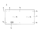
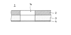
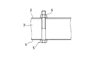
この耐火パネル1は、鋼板2と、鋼板2の一面に貼着され、加熱によって膨張して耐火性断熱層を形成する熱膨張性耐火材料シート3と、熱膨張性耐火材料シート3の他面に貼着された薄鋼板4と、から構成されている。そして、これらの一体に積層された鋼板2、熱膨張性耐火材料シート3および薄鋼板4は、熱膨張性耐火材料シート3が鋼板2および薄鋼板4によって挾持された状態で、周縁部が固定ボルト5およびナット6を介して締結されている。具体的には、固定ボルト5の軸部に熱可塑性材料、例えば、熱可塑性樹脂からなる筒状体7を遊嵌した状態で、鋼板2、熱膨張性耐火材料シート3および薄鋼板4の周縁部に形成された固定穴1aに固定ボルト5の軸部の先端を薄鋼板4側から挿通し、鋼板2側から固定ボルト5の軸部にナット6をねじ込んで締め付けることにより、鋼板2、熱膨張性耐火材料シート3および薄鋼板4を一体に締結する。
This fire-
さらに、耐火パネル1には、離散的に複数個の穴1xが形成されている。すなわち、固定ボルト5およびナット6を介して鋼板2、熱膨張性耐火材料シート3および薄鋼板4を一体に締結した後、パンチング加工によって穴1xが形成されるものである。
Further, the
ここで、鋼板2としては、厚みが1.2〜2.3mmの鋼板が、また、薄鋼板4としては、厚みが0.5mm以下の鋼板が好ましいが、鋼板に限らず、亜鉛メッキ鋼板、亜鉛−アルミ合金メッキ鋼板、塗装鋼板、塩ビ鋼板、ステンレス鋼板など、耐火性を有する各種鋼板を採用することができ、また、厚みも特に限定するものではない。
Here, the
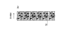
また、熱膨張性耐火材料シート3としては、無機繊維、熱膨張性無機物、無機質バインダーおよび有機質バインダーからなり、図4に示すように、無機繊維31が、該熱膨張性耐火材料シートの表面に対して略法線方向に配向されている他、初期厚みが1〜5mmであり、50kW/m2 の熱量を30分間照射されたときの厚み変化が5〜40倍で、かつ、加熱膨張後の形成された耐火性断熱層のかさ密度が0.5g/cm3 以下であることが好ましい。
The thermally expandable
さらに、耐火パネル1に形成される穴1xとしては、直径が5〜20mmであり、そのピッチが直径の1.2〜2.0倍であることが好ましい。
Further, the
このように構成された耐火パネル1を用いてトンネルの耐火構造を形成する場合は、耐火パネル1を既設または新設のトンネル内に搬入した後、詳細には図示しないが、耐火パネル1に形成された取付穴1bに図示しない耐火パネル取付ボルトを挿入し、トンネル覆工Gの内面と耐火パネル1の背面との間に空気層Sを形成するように、コンクリート覆工Gに埋設したナット(図示せず)に締結すればよい。この場合、後述するように、火災時における熱膨張性耐火材料シート3の膨張を阻害しないように、耐火パネル取付ボルトの頭部が、固定ボルト5の頭部とほぼ同一高さ位置にあるように締結する。
When the fireproof structure of the tunnel is formed using the
トンネル覆工Gの内面と耐火パネル1の背面との間に空気層Sを形成することにより、トンネル覆工Gの漏水の排水空間を確保することができるとともに、トンネル覆工Gに多少の凹凸が存在しても、その凹凸に影響されることなく施工することが可能となる。
By forming an air layer S between the inner surface of the tunnel lining G and the back surface of the
ここで、空気層Sの間隔としては、20〜100mmが好ましく、20〜70mmがさらに好ましい。 Here, as a space | interval of the air layer S, 20-100 mm is preferable and 20-70 mm is more preferable.
この実施形態においては、鋼板2がトンネル覆工Gの内面側に位置するとともに、トンネル内空側に固定ボルト5の軸部が突出するように取り付けた場合を説明したが、薄鋼板4がトンネル覆工Gの内面側に位置するとともに、トンネル内空側に固定ボルト5の軸部が突出するように取り付けてもよい。
In this embodiment, the
したがって、耐火パネル1が取り付けられたトンネルにおいては、耐火パネル1に形成された穴1xを通してトンネル覆工Gの内面を目視観察することができることから、コンクリートのひび割れや漏水などを把握することが可能となり、トンネル覆工Gの保守点検に支障をきたすことがない。また、耐火パネル1は、厚みが小さいため、トンネル覆工Gの内面との間に空気層Sをおいて配設することができ、その空間をトンネル覆工Gからの漏水の排水空間に利用することができるとともに、トンネル内空の建築限界に影響を与えることもない。また、トンネル覆工の内面が薄鋼板4で覆われるため、汚れが付きにくい他、意匠的にも優れたものとなる。さらに、熱膨張性耐火材料シート3は、鋼板2および薄鋼板4に挾持されるため、経年により、熱膨張性耐火材料シート3が剥がれて垂れ下がることもない。
Therefore, in the tunnel to which the
一方、万が一トンネル内で火災が発生した場合には、火災の熱が固定ボルト5、熱可塑性材料製の筒状体7および薄鋼板4に作用し、筒状体7を焼失させるとともに、薄鋼板4を通して熱膨張性耐火材料シート3に均一に熱を供給する。すなわち、火災時の熱を薄鋼板4で一旦受け止めるため、熱膨張性耐火材料シート3が局所的に熱せられることはない。このため、図5に示すように、薄鋼板4を通して熱が供給された熱膨張性耐火材料シート3は、筒状体7が焼失したことによって鋼板2および薄鋼板4の間隔を広げるように膨張して耐火性断熱層3’を形成し、パンチング加工によって耐火パネル1に形成された穴1xの、鋼板2および薄鋼板4に形成された穴を閉鎖するとともに、熱が鋼板2に伝わるのを防止する。
On the other hand, in the unlikely event that a fire occurs in the tunnel, the heat of the fire acts on the fixing
この結果、火災の熱が穴1xおよび空気層Sを通してトンネル覆工Gに伝搬するのを防止することができ、コンクリートに含まれる水分が急速に蒸発してコンクリートが爆裂したり、コンクリートが劣化することを確実に防止できる。さらに、火災時において、空気層Sで対流が生じて局所的に熱せられることが防止され、トンネル覆工Gへの熱影響を緩和できる。
As a result, it is possible to prevent the heat of the fire from propagating to the tunnel lining G through the
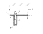
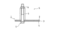
ところで、前述した実施形態においては、トンネル内空側に固定ボルト5の軸部および熱可塑性材料製の筒状体7が位置するように、耐火パネル1をトンネル覆工Gに取り付けた場合を説明したが、このような取付要領では、固定ボルト5の軸部および筒状体7がトンネル内空側に突出し、トンネル内空の建築限界に影響を与えるおそれがある他、意匠的にも利用者に圧迫感を与えるものとなる。このため、図6に示すように、固定ボルト5の軸部および熱可塑性材料製の筒状体7が空気層S側に突出するように、筒状体7を嵌挿した固定ボルト5およびナット6で鋼板2、熱膨張性耐火材料シート3および薄鋼板4を締結することが望ましい。すなわち、鋼板2、熱膨張性耐火材料シート3および薄鋼板4の周縁部に形成された固定穴1aに固定ボルト5の軸部を挿通した後、耐火パネル1の背面側において、固定ボルト5の軸部に熱可塑性材料製の筒状体7を遊嵌するとともに、固定ボルト5の軸部にナット6をねじ込んで締め付けることにより、鋼板2、熱膨張性耐火材料シート3および薄鋼板4を一体に締結すればよい。そして、空気層S側に固定ボルト5の軸部および熱可塑性材料製の筒状体7が位置するように、耐火パネル1をトンネル覆工Gに取り付ければよい
この場合、鋼板2がトンネル覆工Gの内面側に位置するように取り付けても、薄鋼板4がトンネル覆工Gの内面側に位置するように取り付けても、断熱性能の差異はなく、どちらでもかまわない。
By the way, in embodiment mentioned above, the case where the
以上のように本発明によれば、火災時におけるトンネル覆工に対する熱影響を抑えることができるとともに、保守点検が不可欠なトンネル覆工の目視観察が可能となることから、トンネル覆工のひび割れや漏水状況などを把握することができ、トンネル覆工の保守点検に支障をきたすことがない。 As described above, according to the present invention, the thermal influence on the tunnel lining during a fire can be suppressed, and the tunnel lining that requires maintenance and inspection can be visually observed. It is possible to grasp the situation of water leakage, etc., and there will be no hindrance to tunnel lining maintenance inspection.
1 耐火パネル
1a 固定穴
1b 取付穴
1x 穴
2 鋼板
3 熱膨張性耐火材料シート
31 無機繊維
4 薄鋼板
5 固定ボルト
6 ナット
7 熱可塑性材料製の筒状体
G トンネル覆工
S 空気層
DESCRIPTION OF
Claims (11)
Priority Applications (1)
| Application Number | Priority Date | Filing Date | Title |
|---|---|---|---|
| JP2005061799A JP2005290971A (en) | 2004-03-08 | 2005-03-07 | Fireproof panel for tunnel and fireproof structure of tunnel |
Applications Claiming Priority (2)
| Application Number | Priority Date | Filing Date | Title |
|---|---|---|---|
| JP2004064275 | 2004-03-08 | ||
| JP2005061799A JP2005290971A (en) | 2004-03-08 | 2005-03-07 | Fireproof panel for tunnel and fireproof structure of tunnel |
Publications (1)
| Publication Number | Publication Date |
|---|---|
| JP2005290971A true JP2005290971A (en) | 2005-10-20 |
Family
ID=35324210
Family Applications (1)
| Application Number | Title | Priority Date | Filing Date |
|---|---|---|---|
| JP2005061799A Pending JP2005290971A (en) | 2004-03-08 | 2005-03-07 | Fireproof panel for tunnel and fireproof structure of tunnel |
Country Status (1)
| Country | Link |
|---|---|
| JP (1) | JP2005290971A (en) |
Cited By (2)
| Publication number | Priority date | Publication date | Assignee | Title |
|---|---|---|---|---|
| JP2007262862A (en) * | 2006-03-30 | 2007-10-11 | Taiheiyo Material Kk | Metal fireproof decorative panel, fireproof covering structure using the panel |
| KR102540985B1 (en) * | 2021-12-10 | 2023-06-08 | 동의과학대학교 산학협력단 | Appratus and systems for extinguishing fires in electric mobile appartus |
-
2005
- 2005-03-07 JP JP2005061799A patent/JP2005290971A/en active Pending
Cited By (2)
| Publication number | Priority date | Publication date | Assignee | Title |
|---|---|---|---|---|
| JP2007262862A (en) * | 2006-03-30 | 2007-10-11 | Taiheiyo Material Kk | Metal fireproof decorative panel, fireproof covering structure using the panel |
| KR102540985B1 (en) * | 2021-12-10 | 2023-06-08 | 동의과학대학교 산학협력단 | Appratus and systems for extinguishing fires in electric mobile appartus |
Similar Documents
| Publication | Publication Date | Title |
|---|---|---|
| US6574930B2 (en) | Passive film protection system for walls | |
| JP5543744B2 (en) | Fireproof compartment penetration structure | |
| JP5427782B2 (en) | Fire prevention compartment penetration structure and construction method thereof | |
| NO302082B1 (en) | Fireproof panel material for panels, and method for making the panel material | |
| JP2007154566A (en) | Fireproof compartment penetration structure | |
| JP2010139056A (en) | Disaster prevention piping method and fire resistant cover | |
| JP4224559B2 (en) | Construction method of heat-insulated metal pipe for penetration part of fire prevention section and structure of penetration part of fire prevention section | |
| JP2005290971A (en) | Fireproof panel for tunnel and fireproof structure of tunnel | |
| JP5179998B2 (en) | Steel beam fireproof coating structure | |
| JP2009002038A (en) | Unburnable insulation panel | |
| JPH10280576A (en) | Installation structure of heat insulation and fire protection material for building exterior walls | |
| EP3568538B1 (en) | Smoke barrier system | |
| JP2013234459A (en) | Fireproofing protection structure for steelwork | |
| JP5918578B2 (en) | Steel frame fireproof covering structure and construction method thereof | |
| JP2002201732A (en) | Fireproof joint and fireproof connection | |
| JP7518650B2 (en) | Dry backfill construction method for drainage systems and drainage pipes | |
| JP3339621B2 (en) | Fire protection section penetration member | |
| JP2007056537A (en) | Drainage pipe structure and plastic drainage pipe joint | |
| KR102636191B1 (en) | Fireproof sleeve constructed in the lower layer of inter-layer slab and construction method using the same | |
| WO2020136736A1 (en) | Fire-resistant member | |
| JP4938359B2 (en) | Fireproof insulation panel | |
| JP2009174301A (en) | Eaves soffit structure, fire-proof reinforcement body and fire-proof reinforcement method for eaves soffit structure | |
| JP2012237185A (en) | Pass-through structure across fire compartment | |
| JP4421584B2 (en) | Fireproof seal body and fireproof seal structure | |
| JP4936682B2 (en) | Construction structure of soundproof tube |