JP2005290937A - Earthquake-resisting metal fitting - Google Patents
Earthquake-resisting metal fitting Download PDFInfo
- Publication number
- JP2005290937A JP2005290937A JP2004111733A JP2004111733A JP2005290937A JP 2005290937 A JP2005290937 A JP 2005290937A JP 2004111733 A JP2004111733 A JP 2004111733A JP 2004111733 A JP2004111733 A JP 2004111733A JP 2005290937 A JP2005290937 A JP 2005290937A
- Authority
- JP
- Japan
- Prior art keywords
- earthquake
- metal fitting
- resistant metal
- structural frame
- fixed
- Prior art date
- Legal status (The legal status is an assumption and is not a legal conclusion. Google has not performed a legal analysis and makes no representation as to the accuracy of the status listed.)
- Granted
Links
- 239000002184 metal Substances 0.000 title claims abstract description 102
- 239000000463 material Substances 0.000 abstract description 26
- 238000010276 construction Methods 0.000 abstract description 3
- 238000007796 conventional method Methods 0.000 abstract 2
- 238000000034 method Methods 0.000 description 6
- 230000000694 effects Effects 0.000 description 2
- 239000004575 stone Substances 0.000 description 2
- 230000003292 diminished effect Effects 0.000 description 1
- 238000006073 displacement reaction Methods 0.000 description 1
- 238000003780 insertion Methods 0.000 description 1
- 230000037431 insertion Effects 0.000 description 1
- 238000012856 packing Methods 0.000 description 1
- 230000002093 peripheral effect Effects 0.000 description 1
- 230000000630 rising effect Effects 0.000 description 1
- 238000003466 welding Methods 0.000 description 1
- 239000002023 wood Substances 0.000 description 1
Images


Landscapes
- Joining Of Building Structures In Genera (AREA)
- Vibration Prevention Devices (AREA)
Abstract
Description
本発明は、木造建築物の耐震性を向上させる耐震金具に関する。 The present invention relates to an earthquake-resistant metal fitting that improves the earthquake resistance of a wooden building.
従来から家屋に耐震性を持たせるために、柱や梁で構成される木造構造枠の対角に筋交いを張る方法が一般的に用いられている。構造枠のコーナには、筋交いを取り付けることができるように、L字状の金具が固定されている。このL字状の金具の固定は、L字を形成する2つの辺がそれぞれ柱と梁にボルト等で固定されることで行われている。 Conventionally, in order to give a house earthquake resistance, a method of straddling diagonal lines of a wooden structure frame composed of columns and beams is generally used. L-shaped metal fittings are fixed to the corners of the structural frame so that braces can be attached. The L-shaped metal fitting is fixed by fixing the two sides forming the L shape to the column and the beam with bolts or the like.
しかし、地震等によって大きな力が構造枠にかかると、筋交いの金具を引っ張る力が、ボルト等の金具を構造枠に固定する力を上回ってしまい、筋交いの引っ張る力で金具が構造枠から外れてしまうことがある。 However, if a large force is applied to the structural frame due to an earthquake or the like, the force pulling the brace will exceed the force to fix the bracket such as a bolt to the structural frame, and the brace will be detached from the structural frame by the pulling force. It may end up.
また、構造枠が地震等の揺れに耐え切れなくなって平行四辺形状に変形しようとすると、柱と梁で形成される構造枠のコーナ角度が90度より小さく或は大きくなろうとするために、柱と梁の両方で固定されたL字状型の金具は、L字を形成する2辺の角度を小さく或は大きくする向きの力を構造枠から受ける。このような力を何度も受けると、L字を形成する2辺の付け根部分等で金具が分断されて、筋交いを取り付けた効果がなくなってしまうこともある。 In addition, if the structural frame cannot withstand shaking such as an earthquake and tries to deform into a parallelogram, the corner angle of the structural frame formed by the column and the beam tends to be smaller or larger than 90 degrees. The L-shaped bracket fixed by both the beam and the beam receives a force in a direction to reduce or increase the angle of the two sides forming the L shape from the structural frame. When such a force is received many times, the metal fitting is divided at the base portions of the two sides forming the L-shape, and the effect of attaching the braces may be lost.
そこで、本発明は、地震等によって木造建築物に大きな揺れが発生しても、筋交いを構造枠に固定できる耐震金具を提供することを目的とする。 Therefore, an object of the present invention is to provide an earthquake-resistant metal fitting that can fix a brace to a structural frame even when a large shaking occurs in a wooden building due to an earthquake or the like.
本発明の耐震金具は、木造建築物の構造枠の内側の向かい合う部位を突っ張る突張材によって構造枠に押圧される押圧部を備える。押圧部は、構造枠を水平方向に突っ張る突張材にて押圧される水平押圧部と、構造枠を垂直方向に突っ張る突張材にて押圧される垂直押圧部がある。耐震金具は、水平方向と垂直方向の力で構造枠に押圧されるので、筋交が耐震金具を引っ張ろうとしても、構造枠から外れ難い構成となっている。 The earthquake-resistant metal fitting according to the present invention includes a pressing portion that is pressed against the structural frame by a tension member that stretches the facing portion inside the structural frame of the wooden building. The pressing portion includes a horizontal pressing portion that is pressed by a stretching material that stretches the structural frame in the horizontal direction, and a vertical pressing portion that is pressed by a stretching material that stretches the structural frame in the vertical direction. Since the earthquake-resistant metal fitting is pressed against the structural frame by the force in the horizontal direction and the vertical direction, even if the bracing tries to pull the earthquake-resistant metal fitting, it is difficult to come off the structural frame.
また、地震等によって、耐震金具が、L字を形成する2辺のコーナ角度を小さく或は大きくする向きの力を構造枠から受けないようにするために、柱と梁の何れか一方にのみ耐震金具を固定するようにしてもよい。 In addition, in order to prevent the earthquake-resistant metal fittings from receiving a force from the structural frame to reduce or increase the corner angle of the two sides forming the L-shape due to an earthquake or the like, only one of the columns and beams You may make it fix an earthquake-resistant metal fitting.
また、地震等によって、コーナ角度が変化した場合、構造枠の向き合う部分を突っ張る突張材の向きも変化する。コーナ角度の変化に全く追従させずに突張材の向きを一定に保とうとすると、突張材に内部応力が発生して突張材が破壊してしまう可能性がある。コーナ角度の変化による突張材の破壊を防ぐために、コーナ角度の変化に追従させて突張材の向きが変化できるように、突張材の複数箇所をコーチスクリューやボルトで耐震金具に固定するのではなく、構造枠の向かい合う位置に固定された両側の耐震金具の押圧部で挟み込むことだけによって突張材の固定を行ってもよい。 In addition, when the corner angle changes due to an earthquake or the like, the direction of the tension member that stretches the facing portion of the structural frame also changes. If an attempt is made to keep the direction of the struts constant without following any change in the corner angle, internal stress may be generated in the struts and the struts may be destroyed. In order to prevent the breakage of the brace due to a change in the corner angle, fix the multiple parts of the brace to the seismic bracket with a coach screw or bolt so that the direction of the brace can be changed following the change in the corner angle. Instead of this, the tension member may be fixed only by being sandwiched between the pressing portions of the seismic fittings on both sides fixed to the opposite positions of the structural frame.
本発明の耐震金具は、構造枠の内側の向き合う部分を突っ張る突張材によって構造枠に押圧されることができるので、筋交いによって引っ張られても構造枠から外れ難い構成となっている。 Since the earthquake-resistant metal fitting of the present invention can be pressed against the structural frame by a tension member that stretches the inner facing portions of the structural frame, it is difficult to come off the structural frame even when pulled by bracing.
また、耐震金具は、構造枠を構成する柱と梁の一方にのみ固定することができるので、構造枠が変形してコーナ角度が変わっても、切断されるようなことはない。 In addition, since the seismic bracket can be fixed only to one of the pillar and beam constituting the structural frame, even if the structural frame is deformed and the corner angle is changed, it is not cut.
さらに、耐震金具は、突張材を挟み込むことで支持できるので、突張材がコーナ角度の変化に追従して向きを変えることができるために、構造枠が変形しても、突張材が破壊されない。 Furthermore, since the seismic bracket can be supported by sandwiching the bracing material, the bracing material can change its direction following the change in the corner angle. It will not be destroyed.
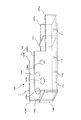
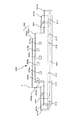
構造枠のコーナに固定される本実施の形態の耐震金具100の斜視図を図1に示す。図1に示すように、耐震金具100は、底部101と該底部101の両側に立設された側壁102a、102bとから構成される隅金具1と、隅金具1に固定される当て材104と、角止め材105を備えている。
FIG. 1 shows a perspective view of the
図1に示すように、上記隅金具1の底部101には、底部101の長辺方向に最低2つの固定穴110、111と、該固定穴110、111の間に仮止穴112が穿孔されている。耐震金具100は、上記固定穴110、111にコーチスクリューや貫通ボルト等を挿通させることで、柱や梁に固定できるようになっている。
As shown in FIG. 1, at the
一方、上記隅金具1の両側壁102a、102bは、高さの高い高側壁部106a、106bと高さの低い低側壁部107a、107bが隣り合っており、段付状となっている。
On the other hand, the
低側壁部107a、107b及び底部101の隅金具1の端部より一定長さ内側には、上記当て材104が溶接されて立設されている。
The abutting
一方、隅金具1の高側壁部106a、106b側の端部には、高側壁部106a、106b及び底部101に角止め材105が溶接されている。さらに、高側壁部106a、106bの角止め材105側には楕円形の連結穴108a、108bが穿孔され、低側壁部107a、107b側には円形の連結穴109a、109bが穿孔されている。
On the other hand,
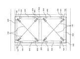
以上のように構成された上記耐震金具100を構造枠の各コーナに固定して、筋交いを張る手順について説明する。
A procedure for securing the brace by fixing the earthquake-
まず、耐震金具100を図2に示すように構造枠の各コーナに固定する。この固定は、底部101を柱401のコーナ部に、角止め材105を梁402のコーナ部に当てがい、仮止穴112にビスを通して耐震金具100を柱401に仮止めし、その後、上記固定穴110、111から柱401にコーチスクリュー等を差し込むことで行う。
First, the earthquake-
このようにして各耐震金具100を構造枠の各コーナに固定すると、各耐震金具100の柱401への固定をより強固にするために、各耐震金具100間に突張材403をはめ込んで各耐震金具100を突張材403でコーナに押圧する。
When each
図2に示す構造枠の左上と右上に固定された耐震金具100と、左下と右下に固定された耐震金具100は、それぞれの底部101が向かい合っており、左上と左下に固定された耐震金具100と、右上と右下に固定された耐震金具100は、それぞれの当て材104が向かい合っている。この向かい合っている底部101間及び当て材104間に、向かい合っている底部101の間隔または当て材104の間隔と同じ長さの突張材403をはめ込む。
The
この結果、図2に示すように、水平方向及び垂直方向に向いた突張材403が各コーナに固定された耐震金具100間にはめ込まれるので、各耐震金具100は、突張材403によって水平方向と垂直方向の力で構造枠のコーナに押圧される。従って、本実施の形態では、当て材104及び底部101が水平押圧部及び垂直押圧部として機能することとなる。
As a result, as shown in FIG. 2, the
以上のように、耐震金具100は、突張材403によって押圧されるので、従来のようにボルト等だけで構造枠に固定されている場合に比べて、著しく強固に構造枠に固定される。また、突張材403で各コーナに固定された各耐震金具100を突っ張ることで、柱401及び梁402の内側に、4つの突張材403にて新たな構造枠が形成されるために、構造枠自体の強度も向上する。
As described above, since the earthquake-
なお、各耐震金具100間にはめ込まれる4つの突張材403のはめ込み順序は、限定されるものではないので、突張材403をはめ込みやすい順序ではめ込めばよい。また、上記したように、左上と右上及び左下と右下の耐震金具100間にはめ込まれる梁402と平行に向いた突張材403の長さは、耐震金具100の底部101の間隔と同じ長さであるために、柱401に固定された耐震金具100の当て材104や側壁部102a、102b等が邪魔となって、耐震金具100の底部101間にはめ込むことができない場合や、はめ込みにくい場合が想定される。このような場合、突張材403を2本に切断して、一本づつ左右の耐震金具100間にはめ込んでもよい。
It should be noted that the fitting order of the four
上記のように各耐震金具100間に上記突張り材403をはめ込むと、突張材403の固定を確実にするために、4つの突張材403の複数箇所にコーチスクリューやボルト等を打ち込んで、各突張材403を柱401や梁402に固定するようにしてもよい。
When the above-mentioned
また高側壁部106a、106bの底部101と反対側の先端が開いてしまうおそれがある場合は、突張材403をはめ込んでから、連結穴108a、108bにボルトを通して、当該ボルトの先端からナットを螺合して、高側壁部106a、106bをボルトとナットで挟み込むことで先端が開いてしまうことを防止してもよい。
If there is a risk that the tip of the
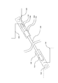
上記のようにして突張材403をはめ込むと、構造枠の対角に固定された耐震金具100間に筋交いを取り付ける。
When the
図3及び図4に示すように、まず、筋交い132の一方が取り付けられる耐震金具100の連結穴109aからボルト120の先端を耐震金具100の内部に挿入し、先端に長ナット133が溶接された筋交い取付部130の基端に設けられた取付穴131をボルト120に挿通する。さらにナット121、ナット122をボルト120に螺合して、ボルト120の先端を連結穴109bに挿入して、ボルト120の先端にナット123を螺合させる。又、壁が薄く、壁表面にナット123が露出するおそれがある場合は、ナット123を螺合させる代わりに、ナット122を高側壁部106bの連結穴109b周辺部分に予め溶接して固定しておき、ボルト120の先端をナット122に螺合してもよい。
As shown in FIG. 3 and FIG. 4, first, the tip of the
次に、筋交い132を取り付ける他方の耐震金具100にも同様にして筋交い取付部140を取り付ける。この筋交い取付部140の先端には、筋交い取付部130に溶接されている長ナット133よりも内径の大きい長ナット136が支持部として溶接されている。
Next, the
筋交い取付部140を取り付けると、上記長ナット133と螺合する径の筋交い132となる長ボルトの先端を上記長ナット136に遊嵌させて挿通させ、長ボルト132の基端を長ナット133に螺合させる。基端を長ナット133に螺合させると、地震等によって筋交い132が取り付けられた対角が長くなろうとして長ナット136が長ボルト132の先端側に移動してしまうことを防ぐために、ストッパとなるナット134、135を長ボルト133の先端側に螺合させる。
When the
ナット134、135を螺合させると、筋交い取付部130、140が回転しないように、ナット121で筋交い取付部130、140を固定する。
When the nuts 134 and 135 are screwed together, the bracing
これにより筋交い132の耐震金具100への取り付けが終わる。
Thereby, the attachment of the
本実施の形態においては、筋交い132の先端が挿通される長ナット136の一方には、上記のようにナット134、135が螺合されているので、長ナット136がナット134、135方向に移動することができないが、他方側、即ち長ボルト133の基端側には、ナット等が螺合されていないので、他方側へは移動することができるようになっている。そのため、地震等によって構造枠が平行四辺形状に変形して、筋交いが取り付けられた構造枠の対角が短くなると、対角の短くなった分だけ、長ナット136が筋交い132の基端側に移動することができるために、構造枠の変形によって筋交い132に圧縮力がかかって筋交い132が変形することを防ぐことができる。
In the present embodiment, since the
以上の方法で、2本の筋交い132をX字状に取り付けると筋交い132の取り付けが終了する。
When the two
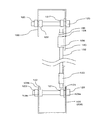
(実施の形態2)
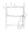
木造家屋では、通常柱の間隔に比べて梁の間隔が大きいために、構造枠が図5に示すように縦長となることが多い。縦長の構造枠に筋交いを取り付けると、筋交いの向きが、垂直方向に近い向きとなる。筋交いが垂直方向に近い向きとなると、筋交いを張ることによって得られる構造枠の変形防止の効果が薄れる。
(Embodiment 2)
In a wooden house, since the interval between beams is larger than the interval between normal columns, the structural frame is often vertically long as shown in FIG. When the brace is attached to the vertically long structural frame, the bracing direction is close to the vertical direction. When the bracing is in a direction close to the vertical direction, the effect of preventing deformation of the structural frame obtained by stretching the bracing is diminished.
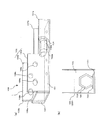
例えば、柱401の間隔が1mであり、梁の間隔が2.4mであるような縦長の構造枠の場合、両柱401の中間部に図5及び図6に示すような耐震金具200を固定する。耐震金具200は、図6に示すように、耐震金具200の中央を線対称の軸にして対称となっている。この耐震金具200は、底部201と該底部201の両側に立設された側壁202a、202bとから構成される中間金具2と2つの当て材204とを備えている。
For example, in the case of a vertically long structural frame in which the interval between the
上記中間金具2の底部201には、底部201の長辺方向に最低4つの固定穴211〜214と、2つの仮止穴215、216が穿孔されている。耐震金具200は、上記固定穴211〜214にコーチスクリューや貫通ボルト等を挿通させることで、柱401に固定できるようになっている。
At least four fixing
図6に示すように上記中間金具2の両側壁202a、202bは、中央部が高くなっており、この高くなっている高側壁部206a、206bと高側壁部206a、206bの左右の低側壁部207a、207bから構成されている。
As shown in FIG. 6, the both
高側壁部206a、206bには、中央に穿孔された楕円形の連結穴209a、209bと、当該連結穴209の両側に穿孔された円形の連結穴208a、208b、210a、210bが設けられている。
The high
上記2つの当て材204は、中間金具2の両端より一定長さ内側で底部201及両側の低側壁部207a、207bに溶接されて、底部201に立設されている。
The two abutting
耐震金具200と耐震金具100を用いて構造枠の耐震性を向上させる施工手順を以下に説明する。
A construction procedure for improving the earthquake resistance of the structural frame using the earthquake
まず、図5に示すように、耐震金具100を構造枠の各コーナに固定し、両側の柱401の同じ高さの位置に耐震金具200を固定する。各耐震金具100の固定は、実施の形態1と同じ方法で行う。一方、耐震金具200の固定は、底部201を柱401側に向けて耐震金具を柱401の中間部に当てがって、仮止穴215、216にビスを通して仮止めし、上記固定穴211〜214にコーチスクリュー等を差し込むことで行う。
First, as shown in FIG. 5, the earthquake-
耐震金具100と耐震金具200を固定すると、次に耐震金具100、200間に突張材403をはめ込む。まず、実施の形態1で説明したように、図5に示す上下それぞれのコーナに固定された耐震金具100の底部101間へ突張材403をはめ込む。
When the earthquake-
次に、左の上下のコーナに固定された2つの耐震金具100と、左の柱401に固定された耐震金具200間と、右の上下のコーナに固定された2つの耐震金具100と、右の柱401に固定された耐震金具200間に突張材403をはめ込む。
Next, between the two earthquake-
上記したように、耐震金具100は柱401に固定されているので、左上、右上のコーナに固定された耐震金具100の当て材104と、左右の柱に固定された耐震金具200の上側の当て材204が向き合い、左下、右下のコーナに固定された耐震金具100の当て材104と、左右の柱に固定された耐震金具200の下側の当て材204が向き合っている。この向き合っている当て材104、204間に、当て材104と当て材204の間隔と同じ長さの突張材403をはめ込む。
As described above, since the earthquake-
最後に、両側の柱401に固定された耐震金具200の底部201間と同じ長さの突張材403を耐震金具200の底部201間にはめ込み、突張材403がずり落ちないようにするために連結穴209a、209bにボルトを通して、高側壁部206a、206bを介してボルトとナットで突張材403を挟み込むことで固定する。このように、高側壁部206a、206bを介してボルトとナットで突張材403を挟み込むことで高側壁部206a、206bの先端が開いてしまうことの防止も図れる。
Finally, in order to prevent the
なお、本実施の形態においても、耐震金具100の底部101間に突張材403をはめ込むことができない場合や、はめ込みにくい場合は、突張材403を2本に切断して、突張材403をはめ込んでもよい。また、耐震金具200の固定に関しては、突張材403を、2つの耐震金具200の連結穴209a、209bにて予めピン接合しておき、この2つの耐震金具200を同時に柱401に固定しても良い。この固定の際には、2つの耐震金具200を柱401に対して斜めにして構造枠内に入れて、その後2つの耐震金具200を柱401の所定位置にずり込ませて移動させる方法が良い。
Also in the present embodiment, when it is not possible to fit the
なお、耐震金具100の場合と同じく、耐震金具200においても、ナット123の螺合に代えてナット122の溶接固定によってボルト120を固定してもよい。
As in the case of the earthquake-
以上のようにして、耐震金具100、200間に突張材403がはめ込まれることで、図5に示すように、縦長の構造枠の内側に正方形に近い構造枠が2つ形成される。耐震金具200を柱の中間部に固定することで、正方形に近い構造枠が形成されるので、縦長の構造枠であっても、立上り角度が約45°の筋交いを取り付けることができる。
As described above, by inserting the
耐震金具100、200間に突張材403をはめ込むと、突張材403をはめ込んで形成された2つの構造枠に筋交い132をX字状に取り付ける。
When the
まず、耐震金具100の連結穴109a、109b及び耐震金具200の連結穴208a、208b、210a、210bに、実施の形態1に記載した筋交い取付部130、140の取り付け方法と同じ方法で筋交い取付部130、140を取り付ける。そして、耐震金具100、200に取り付けられた筋交い取付部130、140に筋交い132の両端を取り付ける。
First, the brace attachment portions are connected to the
(実施の形態3)
上記では、当て材104、204と底部101、201が突張材403にて押圧される場合について説明したが、当て材104、204が立設されていた耐震金具100、200の部位に当て材104、204に代えて、図7(a)、(b)に示すような2つのナット702a、702bと頭が突張材403にて押圧させる方向に向けてナット702a、702bに螺合されるボルト701を設けるようにしてもよい。このナット702aは、耐震金具100、200の底部101、201の中心に、突張材403と平行の向きにボルト701が進退できる向きに溶接されて固定されている。なお、図7(b)に示すように、パッキン703をナット702aの下部に形成して、ナット702aがずれることを防止するようにしても良い。
(Embodiment 3)
In the above description, the case where the abutting
なお、このナット702a、702b、とボルト701を、耐震金具100の水平材(水平方向に突っ張る突張材403)にて押圧される位置に取り付ける形態にすれば、全ての突張材403の取り付け作業が無理なくできる。
If the nuts 702a and 702b and the
このようにボルト701が突張材403と平行方向に進退することができるので、ボルト701を進退させることで、突張材403がはめ込まれる間隔を変更できるために、実施の形態1、2に記載したように、当て材104、204間又は底部101、201間と同じ長さの突張材403でなくても、耐震金具100、200を押圧することができる。そのため当て材104、204に代えてボルト701とナット702を用いると、突張材403をはめ込む間隔と同じ長さに突張材403を加工する手間を省くことができる。また、突張材403をはめ込んでから、ボルト701を進退させることで、突張材403をきっちりとはめ込むことが容易にできる。
Since the
(実施の形態4)
耐震金具100をより強固に柱401に固定し、構造枠がより変形し難いものとするために、図8に示すように上記底部101に、耐震金具100が固定される構造枠の柱401と、それ以外の柱401とを連結する連結手段150を取り付けてもよい。上記連結手段150は、連結用ボルト151と連結用ナット152から構成され、上記連結用ボルト151は、梁402と平行方向に底部101に取り付けられている。
(Embodiment 4)
In order to fix the seismic metal fitting 100 to the
上記連結用ボルト151は、上記耐震金具100が取り付けられた柱401及び、他の柱401を貫通して各柱401にナット152にて固定されるようにする。このように、連結用ボルト151で、多数の柱401を連結することで、柱401の水平方向のずれを防止することもできる。
The connecting
(実施の形態5)
また、柱401と梁402にて構成されている構造枠に耐震金具100、200を固定する場合について説明したが、構造枠の下部が、コンクリートや石等の耐震金具100を固定し難い材質である場合は、コンクリートや石等の上に木材を載せて、この木材に耐震金具100をできれば水平に固定してもよい。
(Embodiment 5)
Moreover, although the case where the earthquake-
(実施の形態6)
耐震金具が固定される柱401の面に背割りSが設けられている場合、耐震金具100、200を柱401に固定するコーチスクリューや貫通ボルト等が背割りSに差し込まれないように、コーチスクリューや貫通ボルト等の差し込み位置に工夫をする方がよい。
(Embodiment 6)
When a split S is provided on the surface of the
例えば、図9(a)、(b)に示すように、背割りSが中央に設けられた柱401に耐震金具100、200を取り付ける場合、耐震金具100、200の底部の中央でなく、中央から所定距離ずれた位置に千鳥状に固定穴901〜904を穿孔してもよい。
For example, as shown in FIGS. 9 (a) and 9 (b), when the
また、上記したように、当て材104、204は、耐震金具100の端部から一定長さ内側に立設されているので、突張材403の当て材104、204の端部の側面が、低側壁部107a、107b、底部101又は低側壁部207a、207b、底部201の3面から形成されるリブによって包持されるので、本実施の形態の耐震金具100、200を用いると、耐震金具の負荷によるねじれを突張材と共に押さえることができる。
Further, as described above, the abutting
上記では、耐震金具100を構造枠のコーナ部分の柱401に固定する場合について説明したが、耐震金具100をコーナ部分の梁402に固定してもよい。
In the above description, the case where the earthquake-
100 200 耐震金具
101 201 底部
104、204 当て材
132 筋交い
400 固定具
401 梁
402 柱
403 突張材
DESCRIPTION OF
Claims (8)
上記構造枠の水平方向に向き合う部位を突っ張る突張材にて上記構造枠に押圧される水平押圧部と、
上記構造枠の垂直方向に向き合う部位を突っ張る突張材にて上記構造枠に押圧される垂直押圧部とを備えたことを特徴とする耐震金具。 In earthquake-resistant metal fittings that are attached to structural frames of wooden buildings and braces are attached,
A horizontal pressing portion that is pressed against the structural frame by a tension member that stretches a portion facing the horizontal direction of the structural frame;
An earthquake-resistant metal fitting, comprising: a vertical pressing portion that is pressed against the structure frame by a tension member that stretches a portion facing the vertical direction of the structure frame.
上記垂直押圧部は、上記突張材にて上下方向から押圧される請求項1に記載の耐震金具。 It is attached in the middle of the pillars that make up the structural frame,
The earthquake-resistant metal fitting according to claim 1, wherein the vertical pressing portion is pressed from above and below by the tension member.
Priority Applications (1)
| Application Number | Priority Date | Filing Date | Title |
|---|---|---|---|
| JP2004111733A JP4503337B2 (en) | 2004-04-06 | 2004-04-06 | Seismic bracket |
Applications Claiming Priority (1)
| Application Number | Priority Date | Filing Date | Title |
|---|---|---|---|
| JP2004111733A JP4503337B2 (en) | 2004-04-06 | 2004-04-06 | Seismic bracket |
Publications (2)
| Publication Number | Publication Date |
|---|---|
| JP2005290937A true JP2005290937A (en) | 2005-10-20 |
| JP4503337B2 JP4503337B2 (en) | 2010-07-14 |
Family
ID=35324177
Family Applications (1)
| Application Number | Title | Priority Date | Filing Date |
|---|---|---|---|
| JP2004111733A Expired - Fee Related JP4503337B2 (en) | 2004-04-06 | 2004-04-06 | Seismic bracket |
Country Status (1)
| Country | Link |
|---|---|
| JP (1) | JP4503337B2 (en) |
Cited By (1)
| Publication number | Priority date | Publication date | Assignee | Title |
|---|---|---|---|---|
| JP2007198069A (en) * | 2006-01-30 | 2007-08-09 | Sekisui House Ltd | Beam-column joint structure |
Citations (4)
| Publication number | Priority date | Publication date | Assignee | Title |
|---|---|---|---|---|
| JPH01173210U (en) * | 1988-05-27 | 1989-12-08 | ||
| JPH09170268A (en) * | 1995-12-20 | 1997-06-30 | Shierutaa Home Kk | Joint device for building member |
| JPH09291606A (en) * | 1996-04-25 | 1997-11-11 | Shierutaa:Kk | Joint device for architectural member |
| JP2003293487A (en) * | 2002-04-03 | 2003-10-15 | American Silverwood Kk | Bearing wall frame and bearing wall structure using the same |
-
2004
- 2004-04-06 JP JP2004111733A patent/JP4503337B2/en not_active Expired - Fee Related
Patent Citations (4)
| Publication number | Priority date | Publication date | Assignee | Title |
|---|---|---|---|---|
| JPH01173210U (en) * | 1988-05-27 | 1989-12-08 | ||
| JPH09170268A (en) * | 1995-12-20 | 1997-06-30 | Shierutaa Home Kk | Joint device for building member |
| JPH09291606A (en) * | 1996-04-25 | 1997-11-11 | Shierutaa:Kk | Joint device for architectural member |
| JP2003293487A (en) * | 2002-04-03 | 2003-10-15 | American Silverwood Kk | Bearing wall frame and bearing wall structure using the same |
Cited By (1)
| Publication number | Priority date | Publication date | Assignee | Title |
|---|---|---|---|---|
| JP2007198069A (en) * | 2006-01-30 | 2007-08-09 | Sekisui House Ltd | Beam-column joint structure |
Also Published As
| Publication number | Publication date |
|---|---|
| JP4503337B2 (en) | 2010-07-14 |
Similar Documents
| Publication | Publication Date | Title |
|---|---|---|
| JP2007519494A (en) | Suspended shelves | |
| JP5004918B2 (en) | Formwork structure for decorative plate member | |
| JP4503337B2 (en) | Seismic bracket | |
| JP2886488B2 (en) | Reinforced metal fittings for buildings | |
| JP2007321499A (en) | Reinforcing device of wooden framework house | |
| JP7762381B2 (en) | Frame reinforcement structure | |
| JP3409137B2 (en) | Bearing wall structure of wooden frame | |
| JP2005344492A (en) | Earthquake resistance reinforcing method for wooden house, metal fitting used for the same and device for preventing pillar from falling out | |
| JP5095502B2 (en) | Fence or handrail structure | |
| JP2023156149A (en) | Crest type rigid frame and architectural structure | |
| JP5190904B1 (en) | Seismic reinforcement structure for wooden houses | |
| JPS5844167Y2 (en) | Connection member for fastening frame fittings in wooden buildings | |
| JP2005315010A (en) | Brace unit | |
| JP2017101414A (en) | Fitting structure of tension rod | |
| JP4038086B2 (en) | Bracing unit mounting structure | |
| JP3739372B2 (en) | Bracing structure in wooden buildings | |
| JP6309327B2 (en) | Reinforcement member for horizontal frame of wooden building and reinforcement method for horizontal frame of wooden building | |
| JP2006249799A (en) | Aseismatic reinforcing member for wooden building | |
| JP2010077645A (en) | Joint structure in wooden building | |
| JP4607978B2 (en) | Reinforcement structure of bracing in wooden buildings | |
| JP5571896B2 (en) | Brace material | |
| JP2002115339A (en) | Column fixing fitting | |
| JPH09189076A (en) | Connection device of structural member for wooden building | |
| JP2007303105A (en) | Aseismatic reinforcing structure | |
| JP2007120001A (en) | Aseismatic reinforcing implement and aseismatic reinforcing structure |
Legal Events
| Date | Code | Title | Description |
|---|---|---|---|
| A621 | Written request for application examination |
Free format text: JAPANESE INTERMEDIATE CODE: A621 Effective date: 20070316 |
|
| A977 | Report on retrieval |
Free format text: JAPANESE INTERMEDIATE CODE: A971007 Effective date: 20081212 |
|
| A131 | Notification of reasons for refusal |
Free format text: JAPANESE INTERMEDIATE CODE: A131 Effective date: 20091209 |
|
| A521 | Written amendment |
Free format text: JAPANESE INTERMEDIATE CODE: A523 Effective date: 20100127 |
|
| TRDD | Decision of grant or rejection written | ||
| A01 | Written decision to grant a patent or to grant a registration (utility model) |
Free format text: JAPANESE INTERMEDIATE CODE: A01 Effective date: 20100414 |
|
| A01 | Written decision to grant a patent or to grant a registration (utility model) |
Free format text: JAPANESE INTERMEDIATE CODE: A01 |
|
| A61 | First payment of annual fees (during grant procedure) |
Free format text: JAPANESE INTERMEDIATE CODE: A61 Effective date: 20100421 |
|
| R150 | Certificate of patent or registration of utility model |
Ref document number: 4503337 Country of ref document: JP Free format text: JAPANESE INTERMEDIATE CODE: R150 Free format text: JAPANESE INTERMEDIATE CODE: R150 |
|
| FPAY | Renewal fee payment (event date is renewal date of database) |
Free format text: PAYMENT UNTIL: 20130430 Year of fee payment: 3 |
|
| FPAY | Renewal fee payment (event date is renewal date of database) |
Free format text: PAYMENT UNTIL: 20130430 Year of fee payment: 3 |
|
| FPAY | Renewal fee payment (event date is renewal date of database) |
Free format text: PAYMENT UNTIL: 20160430 Year of fee payment: 6 |
|
| R250 | Receipt of annual fees |
Free format text: JAPANESE INTERMEDIATE CODE: R250 |
|
| R250 | Receipt of annual fees |
Free format text: JAPANESE INTERMEDIATE CODE: R250 |
|
| R250 | Receipt of annual fees |
Free format text: JAPANESE INTERMEDIATE CODE: R250 |
|
| R250 | Receipt of annual fees |
Free format text: JAPANESE INTERMEDIATE CODE: R250 |
|
| R250 | Receipt of annual fees |
Free format text: JAPANESE INTERMEDIATE CODE: R250 |
|
| R250 | Receipt of annual fees |
Free format text: JAPANESE INTERMEDIATE CODE: R250 |
|
| LAPS | Cancellation because of no payment of annual fees |