JP2007303105A - Aseismatic reinforcing structure - Google Patents
Aseismatic reinforcing structure Download PDFInfo
- Publication number
- JP2007303105A JP2007303105A JP2006130860A JP2006130860A JP2007303105A JP 2007303105 A JP2007303105 A JP 2007303105A JP 2006130860 A JP2006130860 A JP 2006130860A JP 2006130860 A JP2006130860 A JP 2006130860A JP 2007303105 A JP2007303105 A JP 2007303105A
- Authority
- JP
- Japan
- Prior art keywords
- steel
- fastening
- bolt insertion
- fastened
- base
- Prior art date
- Legal status (The legal status is an assumption and is not a legal conclusion. Google has not performed a legal analysis and makes no representation as to the accuracy of the status listed.)
- Pending
Links
Images

Abstract
Description
本発明は、既設木造家屋の所望の一室に設置して耐震強度を補強する耐震補強構造体に関する。 The present invention relates to a seismic reinforcement structure that is installed in a desired room of an existing wooden house to reinforce the seismic strength.
日本の家屋は伝統的に軸組構造の木造家屋であり、特に築後かなりの年数が経ち老朽化して来ると大きな地震が発生したときに梁、桁、柱等に耐震度を超える荷重が加わって損傷したり破壊されて屋根の荷重により家屋全体が倒壊するのおそれがある。この対策として、現状の家屋の土台、梁、柱投を耐震構造に改造することが必要であるが多額の費用と時間が掛かるという問題がある。 Japanese houses are traditionally timbered wooden houses, especially when they are old and have deteriorated for a long time, and when large earthquakes occur, beams, girders, columns, etc. are subjected to loads exceeding the seismic resistance. There is a risk that the entire house will collapse due to the load on the roof. As a countermeasure, it is necessary to remodel the current building foundations, beams, and poles into earthquake-resistant structures, but there is a problem that it takes a lot of cost and time.
そこで、既設建屋の所望の室内に、隣室と連絡する開口部を有する鉄骨組立構造の避難室を設置し、この避難室は、設置すべき室の基床上に設置される鉄骨組土台と、この鉄骨組土台の少なくとも隅角部に結合された複数本の鉄骨柱と、鉄骨柱の上端部に結合された鉄骨組梁と、鉄骨組土台と鉄骨柱及び鉄骨梁間に固定された複数本の鉄骨組壁パネルを備えた構造の耐震避難室付家屋が提案されている(例えば、特許文献1参照)。 Therefore, an evacuation room with a steel structure having an opening communicating with the adjacent room is installed in a desired room of the existing building, and the evacuation room includes a steel frame base installed on the base floor of the room to be installed, A plurality of steel columns coupled to at least the corners of the steel frame foundation, a steel frame beam coupled to the upper end of the steel column, and a plurality of steel frames fixed between the steel frame foundation, the steel column and the steel beam There has been proposed a house with an earthquake-proof evacuation room having a structure including a wall panel (for example, see Patent Document 1).
或いは、既設建屋の所望の室内に、隣室と連絡する開口部を有する鉄骨組立構造の耐震室を設置し、この耐震室は、設置すべき室に対応する形状、寸法を持ち当該室の基床上に設置される鉄骨組土台と、この鉄骨組土台の各辺に結合された複数本づつの鉄骨柱と、それらの鉄骨柱の上端部に結合された鉄骨組梁と、隣接する鉄骨柱間及び鉄骨柱間の鉄骨組土台及び鉄骨組梁間とを結合する鉄骨壁を備え、鉄骨組土台の上には床が設けられ、鉄骨柱と鉄骨壁の室内側表示面には表装壁が張設され、鉄骨組梁の下面には表装天井が張設される構造の耐震室付家屋が提案されている(例えば、特許文献2参照)。
耐震避難室や耐震室付家屋は、その有効性が認識されてきており徐々に普及しつつある。しかしながら、上記提案されている耐震避難室や耐震室付家屋は、構造が複雑であるために部品点数が多く、これに伴い組み付け箇所が多くなり、施工現場における組み付けに手間が掛かる。また、コストが高いという問題がある。 The effectiveness of earthquake-proof evacuation rooms and houses with earthquake-proof rooms has been recognized and is gradually becoming widespread. However, the proposed earthquake-proof evacuation room and the house with the earthquake-proof room have a complicated structure, so there are a large number of parts, and as a result, the number of parts to be assembled increases, which takes time for assembly at the construction site. There is also a problem of high cost.
耐震補強体は、強度を有することは必要不可欠であるが、設置費用を安くするも大切である。従って、十分な強度を有しかつ設置費用を抑えることが耐震構造体を普及させる上で大きな課題である。 It is essential that the seismic reinforcement has strength, but it is also important to reduce the installation cost. Therefore, having a sufficient strength and suppressing the installation cost is a big problem in spreading the seismic structure.
設置費用を安くする構造として、天井板と4本の支柱と床板と一面の側板からなる鉄骨溶接構造の避難箱を建物内に配置することも考えられるが、接合部を現場(家屋内)で溶接することが必要となり、溶接に伴う火災等の発生の問題があり木造家屋内に設置することは困難である。 As a structure to reduce the installation cost, it is possible to arrange a steel welded evacuation box consisting of a ceiling plate, four columns, a floor plate and one side plate in the building. It is necessary to weld, and there is a problem of fire and the like due to welding, so it is difficult to install in a wooden house.
本発明の目的は、十分な耐震性を有すると共に設置費用を抑え、構造が簡単でしかも溶接等の作業を全く不要とした耐震補強構造体を提供することにある。 An object of the present invention is to provide a seismic reinforcement structure that has sufficient seismic resistance, reduces installation costs, has a simple structure, and does not require any work such as welding.
上記目的を達成するために本発明に係わる耐震補強構造体は、既設家屋の所望の一室に設置されて補強する耐震補強構造体であって、
H形鋼からなり水平な上側部両端及び中央の垂直部両端にボルト挿通孔が形成され、前記一室に形成された基礎に設置されて鉄骨組土台を構成する鉄骨土台と、
角形パイプ鋼からなり前記鉄骨組土台の隅部に垂直に配置され隣り合う前記鉄骨土台の端部と対向する側面の下端に前記上側部のボルト挿通孔と対応してボルト挿通孔が形成された鉄骨柱と、
H形鋼からなり水平な下側部両端及び中央の垂直部両端に前記鉄骨柱の対向する側面に形成されたボルト挿通孔と対応してボルト挿通孔が形成され前記各鉄骨柱の上端に配置されて鉄骨組梁を構成する鉄骨梁と、
厚板鋼板により直角二等辺三角形状に形成され直角部を挟む二辺部が一側に直角に折曲されて二つの締結部が形成され、各締結部に前記鉄骨土台及び鉄骨梁及び鉄骨柱のボルト挿通孔と対応してボルト挿通孔が形成され、一側の締結部が前記鉄骨土台の上側部端部又は鉄骨梁の下側部端部に締結され、他側の締結部が前記鉄骨柱の対応する側面に締結される第1の締結部材と、
厚板鋼板により直角二等辺三角形状に形成され直角部を挟む二辺部が一側に直角に折曲されて二つの締結部が形成され、かつ前記直角部が前記鉄骨柱に対応して切り欠かれ、各締結部に前記鉄骨土台及び鉄骨梁のボルト挿通孔と対応してボルト挿通孔が形成され、一側の締結部が前記鉄骨土台又は鉄骨梁の垂直部端部に締結され、他側の締結部が前記鉄骨土台又は鉄骨梁と直交する鉄骨土台又は鉄骨梁の垂直部端部に締結される第2の締結部材と、
前記第1、第2の締結部材の締結部と前記鉄骨土台及び鉄骨梁及び鉄骨柱を締結するボルトとナットとを備えたことを特徴としている。
In order to achieve the above object, the seismic reinforcement structure according to the present invention is a seismic reinforcement structure that is installed and reinforced in a desired room of an existing house,
Bolt insertion holes are formed at both ends of the horizontal upper part and the central vertical part made of H-shaped steel, and are installed on the foundation formed in the one chamber to constitute a steel frame foundation,
Bolt insertion holes corresponding to the bolt insertion holes in the upper part are formed at the lower ends of the side surfaces that are made of square pipe steel and are arranged perpendicular to the corners of the steel frame foundation and facing the ends of the adjacent steel foundations. Steel columns,
A bolt insertion hole is formed at the upper end of each steel column corresponding to the bolt insertion hole formed on the opposite side surface of the steel column at both ends of the horizontal lower portion and the central vertical portion made of H-shaped steel. A steel beam constituting a steel frame beam,
The steel plate, the steel beam, and the steel column are formed at each fastening part by forming two fastening parts by forming a right isosceles triangle shape with a thick steel plate and bending the two sides sandwiching the right angle part at right angles to one side. A bolt insertion hole is formed corresponding to the bolt insertion hole of the steel plate, one fastening portion is fastened to the upper end portion of the steel base or the lower end portion of the steel beam, and the other fastening portion is the steel frame. A first fastening member fastened to a corresponding side of the column;
The steel plate is formed into a right-angled isosceles triangle shape, the two sides sandwiching the right-angled portion are bent at right angles to one side to form two fastening portions, and the right-angled portion is cut corresponding to the steel column. A bolt insertion hole is formed in each fastening part corresponding to the bolt insertion hole of the steel base and the steel beam, and one side fastening part is fastened to the end of the vertical part of the steel base or steel beam. A second fastening member whose side fastening portion is fastened to a vertical end portion of the steel base or steel beam orthogonal to the steel base or steel beam;
A bolt and a nut for fastening the fastening portion of the first and second fastening members, the steel base, the steel beam, and the steel column are provided.
既設家屋の耐震補強すべき一室に施工したべた基礎に4本の鉄骨土台を四角形を形成するように配置して隣り合う鉄骨土台の各垂直部の両端を第2の締結部材によりボルトとナットで固定して鉄骨組土台を形成する。この鉄骨組土台の隅部に鉄骨柱を配置して各鉄骨土台の端部とこの鉄骨土台の端部と対向する鉄骨柱の側面とを第1の締結部材によりボルトとナットで固定して垂設する。そして、鉄骨組土台の隅部に垂設した鉄骨柱の対向する側面の上端と鉄骨梁の両端をそれぞれ第1の締結部材によりボルトとナットで固定すると共に、隣り合う鉄骨梁の垂直部の両端を第2の締結部材によりボルトとナットで固定する。 Four steel foundations are arranged on a solid foundation constructed in a room to be seismically strengthened in an existing house, forming a quadrangle, and both ends of each vertical part of adjacent steel foundations are bolts and nuts using second fastening members To fix the steel frame base. Steel columns are arranged at the corners of the steel frame foundation, and the ends of the steel frames and the side surfaces of the steel columns opposite to the ends of the steel frame are fixed by bolts and nuts with a first fastening member. Set up. And the upper end of the opposite side of the steel column suspended from the corner of the steel frame foundation and both ends of the steel beam are fixed with bolts and nuts by the first fastening members, respectively, and both ends of the vertical part of the adjacent steel beam Is fixed with a bolt and a nut by a second fastening member.
鉄骨組土台を形成する鉄骨土台同士、及び鉄骨組梁を形成する鉄骨梁同士を直角二等辺三角形をなす第2の締結部材により締結し、鉄骨組土台及び鉄骨組梁と鉄骨柱とを直角二等辺三角形をなす第1の締結部材により締結することで、上下左右方向及び斜め方向からの荷重に対する強度が確保される。また、各締結部をボルトとナットで締結することで溶接作業を全く不要とし木造建屋における屋内作業を安全に行うことができる。 The steel foundations forming the steel frame foundations and the steel beams forming the steel frame beams are fastened by a second fastening member having a right-angled isosceles triangle, and the steel frame foundation, the steel frame beam, and the steel column are By fastening with the first fastening member having an equilateral triangle, the strength against the load from the up / down / left / right direction and the oblique direction is ensured. Further, by fastening each fastening portion with a bolt and a nut, no welding work is required, and indoor work in a wooden building can be performed safely.
また、本発明の請求項2に記載の耐震補強構造体は、請求項1に係わる耐震補強構造体において、前記鉄骨組土台を構成する鉄骨土台同士を締結する第2の締結部材は、前記基礎に植設されているアンカーボルトに固定されることを特徴としている。
Moreover, the seismic reinforcement structure according to
鉄骨組土台を形成する第2の締結部材を基礎のアンカーボルトに固定して鉄骨組土台を固定する。これにより、耐震補強構造体を所望の室内に強固に設置することが可能である。 The second fastening member forming the steel frame foundation is fixed to the anchor bolt of the foundation to fix the steel frame foundation. Thereby, it is possible to install the seismic reinforcement structure firmly in a desired room.
また、本発明の請求項3に記載の耐震補強構造体は、請求項1又は請求項2に係わる耐震補強構造体において、前記鉄骨組梁は対角線上に位置する第2の締結部材同士が筋違いで結合されていることを特徴としている。
Further, the seismic reinforcing structure according to
耐震補強構造体の鉄骨組梁に筋違いを設けることで更なる強度の向上を図ることが可能となり、十分な耐久力を得ることが可能である。 It is possible to further improve the strength by providing a difference in the steel frame beam of the seismic reinforcement structure, and it is possible to obtain sufficient durability.
本発明によると、鉄骨土台及び鉄骨梁をH形鋼で、鉄骨柱を角形パイプ鋼で形成し、これらを直角二等辺三角形状の第1、第2の締結部材で締結することにより、十分な強度を持たせることが出来る。特に、第1、第2の締結部材を直角二等辺三角形とすることで斜め方向の加重に対して極めて有効であり、耐震強度の向上を図ることができる。また、各締結部をボルトで締結することにより溶接を全く使用する必要がなく、木造建屋における屋内作業を安全に行うことが可能である。更に構造が極めて簡単でありコストの低減を図ることが可能であり、組付作業が簡単であることと相俟って設置費用を大幅に安価にすることができる。 According to the present invention, the steel base and the steel beam are formed of H-shaped steel, the steel column is formed of rectangular pipe steel, and these are fastened by the first and second fastening members having a right isosceles triangle shape. Strength can be given. In particular, by making the first and second fastening members into right-angled isosceles triangles, it is extremely effective against the load in the oblique direction, and the seismic strength can be improved. Moreover, it is not necessary to use welding at all by fastening each fastening part with a bolt, and indoor work in a wooden building can be performed safely. Furthermore, the structure is extremely simple and the cost can be reduced, and the installation cost can be greatly reduced in combination with the simple assembly work.
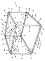
以下、本発明の実施形態に係わる耐震補強構造体について図面に基づいて説明する。図1は、本発明に係わる耐震補強構造体の斜視図を示し、耐震補強構造体1は、既設家屋の所望の一室に設置されて補強するためのもので、前記一室に形成された図示しないべた基礎に設置される鉄骨組土台2、下端部が鉄骨組土台2の四隅に垂設される4本の鉄骨柱3、これら4本の鉄骨柱の上端部に配設される鉄骨組梁4、及び鉄骨組土台2と鉄骨柱3、鉄骨柱3と鉄骨組梁4をそれぞれ締結する第1の締結部材5、鉄骨組土台の鉄骨土台11同士、鉄骨組梁の鉄骨梁12同士をそれぞれ締結する第2の締結部材6、及び鉄骨組梁4に設けられた筋違い(筋交い)7からなる。
Hereinafter, the earthquake-proof reinforcement structure concerning embodiment of this invention is demonstrated based on drawing. FIG. 1 is a perspective view of a seismic reinforcement structure according to the present invention. The seismic reinforcement structure 1 is installed in a desired room of an existing house and is reinforced, and is formed in the one room. A
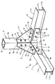
鉄骨組土台2は、4本の鉄骨土台11の各両端部を第2の締結部材6により締結して形成される。図2に示すように鉄骨土台11は、H形鋼により形成されており、水平な上側部11a、下側部11b、及び中央の垂直部11cからなる。上側部11aの一側(内側)縁部の両端にボルト挿通孔11dが例えば2つ長手方向に沿って所定の間隔で形成されており、垂直部11cの両端にボルト挿通孔11eが例えば2つ長手方向に沿って所定の間隔で形成されている。
The
鉄骨柱3は、角形パイプ鋼により形成されており、内側の隣り合う側面3a,3bの下端かつ鉄骨土台11の高さよりも上方所定位置にそれぞれボルト挿通孔3d,3eが例えば2つずつ上下方向に沿って所定の間隔で形成されている。同様に側面3a,3bの図示しない上端に鉄骨組梁3の高さ(鉄骨梁12の高さ)よりも下側の所定位置にボルト挿通孔が上下方向に沿って所定の間隔で形成されている。即ち、鉄骨柱3は、内側の隣り合う側面3a,3bの上下両端所定位置に前記ボルト挿通孔が対称に穿設されている。これにより、鉄骨柱3は、上下の区別無く使用することが可能となる。
The
鉄骨組梁4は、4本の鉄骨梁12の各両端部を第2の締結部材6により締結して形成される。鉄骨梁12は、図2に示す鉄骨土台11と全く同様に形成されており、図2に示す鉄骨土台11の上下を入れ替えた状態で使用することができるため詳細な図面は省略する。また、図1において鉄骨梁12の鉄骨土台11と対応する各部位に対応する符号を付してある。
The steel frame beam 4 is formed by fastening each end portion of the four
図2に示すように第1の締結部材5は、直角二等辺三角形状をなし直角部を挟む二辺部が一側(内側)に直角に折曲されて締結部5a,5bとされている。そして、各締結部5a,5bには鉄骨土台11の上側部11aのボルト挿通孔11d、鉄骨柱3のボルト挿通孔3d,3eと対応する位置にボルト挿通孔5d,5eが形成されている。これらのボルト挿通孔5d,5eは、対称位置に形成されており、上下左右の区別無く使用可能とされている。この第1の締結部材5は、厚板(6mm程度)鋼板をプレス加工して形成されている。
As shown in FIG. 2, the
図2に示すように第2の締結部材6は、直角二等辺三角形状をなし直角部を挟む二辺部が一側(内側)に直角に折曲されて締結部6a,6bとされかつ直角部が鉄骨柱3の側面3a,3bと対応して直角に切り欠かれた形状とされている。そして、各締結部6a,6bに鉄骨土台11の垂直部11cのボルト挿通孔11eと対応する位置にそれぞれボルト挿通孔6d,6eが形成されている。これらのボルト挿通孔6d,6eは、対称位置に形成されており、上下左右の区別無く使用可能とされている。また、三角形状の平板部6cの略中央に穴6fが形成されている。この穴6fは、アンカーボルト又は筋違いと締結するためのものである。この第2の締結部材6は、第1の締結部材5と同様に厚板(6mm程度)鋼板をプレス加工して形成されている。
As shown in FIG. 2, the
以下に上述した耐震補強構造体1を既設の木造家屋の一室に設置する場合について説明する。既設木造家屋の耐震補強すべき一室の床及び天井を解体して取り除き、べた基礎を施工する。そして、図1に示すように前記べた基礎に4本の鉄骨土台11を、隣り合う鉄骨土台11の各端部間に鉄骨柱3が入る隙間をあけて直角をなすようにして四角形を形成するように配置し、図2に示すように隣り合う鉄骨土台11の各垂直部11c間に第2の締結部材6を配置し、平面状の三角部6cの穴6fに前記べた基礎に植設されている図示しないアンカーボルトを挿入する。
The case where the earthquake-proof reinforcement structure 1 mentioned above is installed in one room of the existing wooden house is demonstrated below. Dismantle and remove the floor and ceiling of an existing wooden house that should be seismically reinforced, and construct a solid foundation. Then, as shown in FIG. 1, four
そして、図2及び図3に示すように締結部6a,6bを各垂直部11c、11cの内側面に当接させて対応する各ボルト挿通孔11e,11eと6d,6eにそれぞれ締結用のボルト15を垂直部11cの外側から挿通し内側でナット16を螺合して仮止めする。また、前記アンカーボルトにもナットを螺合して仮止めする。このようにして、4本の鉄骨土台11を組み付けた後各ボルト15をトルクレンチで所定のトルクで強固に締め付けて締結部材6と鉄骨土台11とを強固に締結固定する。また、前記アンカーボルトにナットを締め付けて締結部材6を前記べた基礎に固定する。このようにして鉄骨組土台2が形成される。なお、ボルト15は、ハイテンションボルト又は構造用トレーシア形高力ボルト(JFEトルクボルト、通称シャーボルト)と称されるボルトが使用される。
2 and 3, the
次に、鉄骨柱3の側面3a,3bの下端部にそれぞれ第1の締結部材5の締結部5bを当接して対応するボルト挿通孔3d,3eと5e,5eにボルト15を挿通してナット16を螺合して仮止めしておく。この場合、ボルト15は、鉄骨柱3の開口端3cから挿入して軸部を外側に突出させてナット16を螺合させる。ボルト15を鉄骨柱3の内側から挿入して外側にナット16を螺合させることでボルト15の締め付け作業が容易となる。同様にして鉄骨柱3の側面3a,3bの上端にもそれぞれ締結部材5の締結部5bを仮止めしておく。
Next, the
次に、前記鉄骨柱3を隣り合う鉄骨土台11の各端部間の隙間に配置して側面3a,3bにそれぞれ仮止めした第1の締結部材5の締結部5aを鉄骨土台11,11の上側部11a,11aに載置し、各上側部11aのボルト挿通孔11dと締結部5aのボルト挿通孔5dとを合致させて下方からボルト15を挿入して上側にナット16を螺合させて仮止めする。上側部11aの下方からボルト15を挿通し上側からナット16を螺合することでボルト15の締め付け作業が容易となる。このようにして鉄骨組土台2の四隅に鉄骨柱3を組み付ける。
Next, the
そして、各鉄骨柱3の垂直を確認しながら各締結部材5のボルト15をトルクレンチで締め付けて垂直に固定する。このようにして、鉄筋組土台2の四隅に鉄骨柱3を垂設する。各鉄骨柱3は、前記一室の四隅の柱の内側に隣接して配置される。これにより、前記一室の喪失面積が既設の柱の近傍隅部分のみとなり、略従来の室内空間を確保することができる。
And the
次に、図1に示す鉄骨梁12の下側部12aの両端を両側の鉄骨柱3に仮止めされた第1の締結部材5の締結部5a(図3参照)に載置し、各ボルト挿通孔に上側からボルト15を挿通して下側にナット16を螺合して仮止めする。このようにして4本の鉄骨柱3の上端に4本の鉄骨梁12を組み付ける。次いで、図3に示す場合と同様に隣り合う鉄骨梁12の垂直部12c間に第2の締結部材を配置してボルト15とナット16とにより仮止めする。
Next, both ends of the
次いで、各鉄骨梁12の水平を確認しながら各ボルト15とナット16をトルクレンチで締め付けて固定して鉄骨組梁4を形成する。そして、図1に示すように鉄骨組梁4の対角線上に対向する隅部の第2の締結部材6間にそれぞれ筋違い7,7を取り付ける。筋違い7は、両端部がそれぞれ対向する締結部材6の三角部6cの穴6fを介してこれらの締結部材6に張設され、ターンバックル7aにより緊締される。
Next, the
耐震補強構造体1は、鉄骨組土台2を形成する4本の鉄骨土台11同士、鉄骨組梁4を形成する4本の鉄骨梁12同士を直角二等辺三角形をなし平板部6cを有する第2の締結部材6により締結し、鉄骨組土台2及び鉄骨組梁4と鉄骨柱3とを直角に等辺三角形をなし平板部5cを有する第1の締結部材5により締結することで、上下左右方向及び斜め方向からの荷重に対する強度が確保され、更に、鉄骨組梁4に筋違い7を設けることで更に強度が向上して十分な耐久力を得ることが可能である。しかも、各締結部をボルト15とナット16で締結することで溶接作業を全く不要とし木造建屋における屋内作業を安全に行うことができる。
The seismic reinforcement structure 1 is a second structure in which the four
上述したようにして既設家屋の一室に耐震補強構造体1を設置する。そして、図1に示すように鉄筋土台11の上側部11aに固設した複数の留め金具13を前記一室の図示しない土台に固定し、鉄筋梁12の上側部12aに固設した複数の留め金具14を前記一室の図示しない梁に固定する。これにより、耐震補強構造体1を設置した前記一室の隣室も補強することが可能となり、家屋全体の耐震強度が向上する。そして、地震発生の際に耐震補強構造体1により補強した前記一室に避難することで被害を免れることが可能となる。
As described above, the seismic reinforcement structure 1 is installed in a room of an existing house. Then, as shown in FIG. 1, a plurality of
1 耐震補強構造体
2 鉄骨組土台
3 鉄骨柱
3a,3b 側面
3c 開口端
3d,3e ボルト挿通孔
4 鉄骨組梁
5 第1の締結部材
5a,5b 締結部
5c 平板部
5d,5e ボルト挿通孔
6 第2の締結部材
6a,6b 締結部
6c 平板部
6d,6e ボルト挿通孔
6f 穴
7 筋違い
7a ターンバックル
11 鉄骨土台
11a 上側部
11b 下側部
11c 垂直部
11d,11e ボルト挿通孔
12 鉄骨梁
12a 下側部
12b 上側部
12c 垂直部
13,14 留め金具
15 ボルト
16 ナット
DESCRIPTION OF SYMBOLS 1
Claims (3)
H形鋼からなり水平な上側部両端及び中央の垂直部両端にボルト挿通孔が形成され、前記一室に形成された基礎に設置されて鉄骨組土台を構成する鉄骨土台と、
角形パイプ鋼からなり前記鉄骨組土台の隅部に垂直に配置され隣り合う前記鉄骨土台の端部と対向する側面の下端に前記上側部のボルト挿通孔と対応してボルト挿通孔が形成された鉄骨柱と、
H形鋼からなり水平な下側部両端及び中央の垂直部両端に前記鉄骨柱の対向する側面に形成されたボルト挿通孔と対応してボルト挿通孔が形成され前記各鉄骨柱の上端に配置されて鉄骨組梁を構成する鉄骨梁と、
厚板鋼板により直角二等辺三角形状に形成され直角部を挟む二辺部が一側に直角に折曲されて二つの締結部が形成され、各締結部に前記鉄骨土台及び鉄骨梁及び鉄骨柱のボルト挿通孔と対応してボルト挿通孔が形成され、一側の締結部が前記鉄骨土台の上側部端部又は鉄骨梁の下側部端部に締結され、他側の締結部が前記鉄骨柱の対応する側面に締結される第1の締結部材と、
厚板鋼板により直角二等辺三角形状に形成され直角部を挟む二辺部が一側に直角に折曲されて二つの締結部が形成され、かつ前記直角部が前記鉄骨柱に対応して切り欠かれ、各締結部に前記鉄骨土台及び鉄骨梁のボルト挿通孔と対応してボルト挿通孔が形成され、一側の締結部が前記鉄骨土台又は鉄骨梁の垂直部端部に締結され、他側の締結部が前記鉄骨土台又は鉄骨梁と直交する鉄骨土台又は鉄骨梁の垂直部端部に締結される第2の締結部材と、
前記第1、第2の締結部材の締結部と前記鉄骨土台及び鉄骨梁及び鉄骨柱を締結するボルトとナットとを備えたことを特徴とする耐震補強構造体。 A seismic reinforcement structure that is installed and reinforced in a desired room of an existing house,
Bolt insertion holes are formed at both ends of the horizontal upper part and the central vertical part made of H-shaped steel, and are installed on the foundation formed in the one chamber to constitute a steel frame foundation,
Bolt insertion holes corresponding to the bolt insertion holes in the upper part are formed at the lower ends of the side surfaces that are made of square pipe steel and are arranged perpendicular to the corners of the steel frame foundation and facing the ends of the adjacent steel foundations. Steel columns,
A bolt insertion hole is formed at the upper end of each steel column corresponding to the bolt insertion hole formed on the opposite side surface of the steel column at both ends of the horizontal lower portion and the central vertical portion made of H-shaped steel. A steel beam constituting a steel frame beam,
The steel plate, the steel beam, and the steel column are formed at each fastening part by forming two fastening parts by forming a right isosceles triangle shape with a thick steel plate and bending the two sides sandwiching the right angle part at right angles to one side. A bolt insertion hole is formed corresponding to the bolt insertion hole of the steel plate, one fastening portion is fastened to the upper end portion of the steel base or the lower end portion of the steel beam, and the other fastening portion is the steel frame. A first fastening member fastened to a corresponding side of the column;
The steel plate is formed into a right-angled isosceles triangle shape, the two sides sandwiching the right-angled portion are bent at right angles to one side to form two fastening portions, and the right-angled portion is cut corresponding to the steel column. A bolt insertion hole is formed in each fastening part corresponding to the bolt insertion hole of the steel base and the steel beam, and one side fastening part is fastened to the end of the vertical part of the steel base or steel beam. A second fastening member whose side fastening portion is fastened to a vertical end portion of the steel base or steel beam orthogonal to the steel base or steel beam;
A seismic reinforcement structure comprising a fastening portion of the first and second fastening members, and a bolt and a nut for fastening the steel base, the steel beam, and the steel column.
Priority Applications (1)
| Application Number | Priority Date | Filing Date | Title |
|---|---|---|---|
| JP2006130860A JP2007303105A (en) | 2006-05-09 | 2006-05-09 | Aseismatic reinforcing structure |
Applications Claiming Priority (1)
| Application Number | Priority Date | Filing Date | Title |
|---|---|---|---|
| JP2006130860A JP2007303105A (en) | 2006-05-09 | 2006-05-09 | Aseismatic reinforcing structure |
Publications (1)
| Publication Number | Publication Date |
|---|---|
| JP2007303105A true JP2007303105A (en) | 2007-11-22 |
Family
ID=38837271
Family Applications (1)
| Application Number | Title | Priority Date | Filing Date |
|---|---|---|---|
| JP2006130860A Pending JP2007303105A (en) | 2006-05-09 | 2006-05-09 | Aseismatic reinforcing structure |
Country Status (1)
| Country | Link |
|---|---|
| JP (1) | JP2007303105A (en) |
Cited By (4)
| Publication number | Priority date | Publication date | Assignee | Title |
|---|---|---|---|---|
| CN101899865A (en) * | 2009-05-26 | 2010-12-01 | 大场喜和 | Earthquake resistant structure body and antidetonation construction method |
| CN102936967A (en) * | 2012-11-15 | 2013-02-20 | 北京筑福建设工程有限责任公司 | Safety refuge bin modified from old abandoned house masonry structure |
| CN103437575A (en) * | 2013-08-23 | 2013-12-11 | 江苏中核华纬工程设计研究有限公司 | Steel structure for nuclear power module |
| CN109403627A (en) * | 2018-12-03 | 2019-03-01 | 广州景兴建筑科技有限公司 | A kind of building aluminum dipping form back cord yin-yang angle reinforces link system |
-
2006
- 2006-05-09 JP JP2006130860A patent/JP2007303105A/en active Pending
Cited By (4)
| Publication number | Priority date | Publication date | Assignee | Title |
|---|---|---|---|---|
| CN101899865A (en) * | 2009-05-26 | 2010-12-01 | 大场喜和 | Earthquake resistant structure body and antidetonation construction method |
| CN102936967A (en) * | 2012-11-15 | 2013-02-20 | 北京筑福建设工程有限责任公司 | Safety refuge bin modified from old abandoned house masonry structure |
| CN103437575A (en) * | 2013-08-23 | 2013-12-11 | 江苏中核华纬工程设计研究有限公司 | Steel structure for nuclear power module |
| CN109403627A (en) * | 2018-12-03 | 2019-03-01 | 广州景兴建筑科技有限公司 | A kind of building aluminum dipping form back cord yin-yang angle reinforces link system |
Similar Documents
| Publication | Publication Date | Title |
|---|---|---|
| KR101880494B1 (en) | Core wall seismic reinforcement structure and construction method of the same | |
| US20070151192A1 (en) | Multi-Purpose Construction Panel and Method | |
| US20150033641A1 (en) | Earthquake resistant reinforcement apparatus, earthquake resistant building, and an earthquake resistant reinforcing method | |
| JP2007239388A (en) | Fitting for constructing dome and dome construction method | |
| US20130259563A1 (en) | Universal construction bracket method and apparatus | |
| JP2007303105A (en) | Aseismatic reinforcing structure | |
| JP3762689B2 (en) | Connection structure of wall frame panel and floor slab foundation | |
| JP5475054B2 (en) | Seismic shelter reinforcement method and seismic shelter with high seismic strength | |
| JP2006241892A (en) | Aseismatic structure of house and its construction method | |
| JP3072284B2 (en) | Architectural metal frame panel body and its construction method | |
| JP4395030B2 (en) | Detached houses | |
| JP5190904B1 (en) | Seismic reinforcement structure for wooden houses | |
| JP7363873B2 (en) | How to renovate a building | |
| JP7428168B2 (en) | How to renovate the eaves | |
| JP2003003672A (en) | Reinforcing method for building | |
| JP7374411B2 (en) | Road surface earthquake reinforcement structure | |
| JP4654674B2 (en) | How to install seismic reinforcement brackets for wooden buildings | |
| JP7363523B2 (en) | Beam end reinforcement structure | |
| JP5095424B2 (en) | Wall panel mounting structure and mounting method | |
| JP2008255713A (en) | Wooden building and its seismic reinforcement method | |
| JP7281088B2 (en) | Merit prevention anchor hardware | |
| JP6410367B2 (en) | Reinforcing brackets for wooden buildings | |
| JP2007056643A (en) | Room-reinforcing frame of building and room-reinforcing structure of building using the same | |
| JP2920275B2 (en) | Side wall panel mounting structure | |
| JPH08277587A (en) | Framework bearing wall and frame work construction method based on its application |