JP2005290928A - Cap for construction machine - Google Patents
Cap for construction machine Download PDFInfo
- Publication number
- JP2005290928A JP2005290928A JP2004111267A JP2004111267A JP2005290928A JP 2005290928 A JP2005290928 A JP 2005290928A JP 2004111267 A JP2004111267 A JP 2004111267A JP 2004111267 A JP2004111267 A JP 2004111267A JP 2005290928 A JP2005290928 A JP 2005290928A
- Authority
- JP
- Japan
- Prior art keywords
- cab
- bracket
- cover
- interior
- cab body
- Prior art date
- Legal status (The legal status is an assumption and is not a legal conclusion. Google has not performed a legal analysis and makes no representation as to the accuracy of the status listed.)
- Granted
Links
- 238000010276 construction Methods 0.000 title claims description 20
- 238000004378 air conditioning Methods 0.000 description 20
- 238000005452 bending Methods 0.000 description 7
- 230000002452 interceptive effect Effects 0.000 description 6
- 230000001143 conditioned effect Effects 0.000 description 5
- 238000000926 separation method Methods 0.000 description 3
- 238000009412 basement excavation Methods 0.000 description 2
- 230000000694 effects Effects 0.000 description 2
- 239000000446 fuel Substances 0.000 description 2
- 238000003780 insertion Methods 0.000 description 2
- 230000037431 insertion Effects 0.000 description 2
- 230000002093 peripheral effect Effects 0.000 description 2
- 239000002689 soil Substances 0.000 description 2
- 125000006850 spacer group Chemical group 0.000 description 2
- XLYOFNOQVPJJNP-UHFFFAOYSA-N water Substances O XLYOFNOQVPJJNP-UHFFFAOYSA-N 0.000 description 2
- 229910000831 Steel Inorganic materials 0.000 description 1
- 239000002828 fuel tank Substances 0.000 description 1
- 239000010720 hydraulic oil Substances 0.000 description 1
- 238000002955 isolation Methods 0.000 description 1
- 239000004973 liquid crystal related substance Substances 0.000 description 1
- 238000004519 manufacturing process Methods 0.000 description 1
- 238000012986 modification Methods 0.000 description 1
- 230000004048 modification Effects 0.000 description 1
- 239000003921 oil Substances 0.000 description 1
- 239000010959 steel Substances 0.000 description 1
- 238000011144 upstream manufacturing Methods 0.000 description 1
Images

Landscapes
- Component Parts Of Construction Machinery (AREA)
Abstract
Description
本発明は、例えば油圧ショベル、油圧クレーン等に用いて好適な建設機械用キャブに関する。 The present invention relates to a construction machine cab suitable for use in, for example, a hydraulic excavator, a hydraulic crane, or the like.
一般に、建設機械としての油圧ショベルは、自走可能な下部走行体と、該下部走行体上に旋回可能に搭載された上部旋回体と、該上部旋回体の前側に俯仰動可能に設けられた作業装置とによって大略構成されている。 In general, a hydraulic excavator as a construction machine is provided with a self-propelled lower traveling body, an upper revolving body that is turnably mounted on the lower traveling body, and a front-rear side of the upper revolving body that can be raised and lowered. It is roughly constituted by a working device.
また、上部旋回体は、旋回フレーム上の左前側に位置してキャブを有している。この油圧ショベルのキャブは、旋回フレーム上に設けられ、前面部、後面部、左側面部、右側面部および天井面部からなる内部に運転室を画成する中空なキャブ本体と、該キャブ本体内に位置して設けられ、オペレータが着座する運転席と、該運転席の下側に設けられた床板と、前記運転席の周囲に位置して前記キャブ本体内に装備された内装品とにより大略構成されている。そして、キャブ本体内の内装品としては、レバー、ペダル等の操作装置、スイッチ、モニタ装置等の電気部品、キャブ内に調和空気を供給する空調ユニット、空調ダクト等がある。 The upper swing body has a cab located on the left front side on the swing frame. The cab of this excavator is provided on a revolving frame, and includes a hollow cab main body that defines a driver's cab inside a front portion, a rear surface portion, a left side surface portion, a right side surface portion, and a ceiling surface portion, and is positioned within the cab main body. A driver's seat on which the operator is seated, a floor board provided below the driver's seat, and an interior part located around the driver's seat and installed in the cab body. ing. And as interior goods in a cab main body, there are operation parts, such as a lever and a pedal, electric parts, such as a switch and a monitor, an air-conditioning unit which supplies conditioned air in a cab, an air-conditioning duct, etc.
ここで、空調装置の室内機となる空調ユニットは、例えば運転席の後側に配設され、空調ダクトは、左側面部に設けられた乗降口からの乗り降りに邪魔にならないように、運転席の右側をキャブ本体の右側面部に沿って前側に延びている。また、運転席の右前側には、空調ダクトを覆うダクトカバーが設けられ、該ダクトカバーには、空調ユニットから空調ダクトを介して供給される調和空気をキャブ内に吹出す吹出口が設けられている。さらに、ダクトカバーには、作業状態等の情報をオペレータに向け表示するモニタ装置が取付けられている。そして、ダクトカバーは、ボルト等を用いてキャブ本体の右側面部に取付けられている(例えば、特許文献1、特許文献2参照)。 Here, the air conditioning unit that is the indoor unit of the air conditioner is disposed, for example, on the rear side of the driver's seat, and the air conditioning duct is installed in the driver's seat so as not to obstruct getting on and off from the entrance / exit provided on the left side surface portion. The right side extends forward along the right side surface of the cab body. Further, a duct cover that covers the air conditioning duct is provided on the right front side of the driver's seat, and the duct cover is provided with a blowout port that blows conditioned air supplied from the air conditioning unit through the air conditioning duct into the cab. ing. Furthermore, a monitor device for displaying information such as work status to the operator is attached to the duct cover. The duct cover is attached to the right side surface portion of the cab body using bolts or the like (see, for example, Patent Document 1 and Patent Document 2).
ところで、上述した従来技術による油圧ショベルのキャブでは、例えばキャブ本体が損傷した場合にはこのキャブ本体を新しいものに交換することがある。また、標準仕様のキャブ本体をトンネル内作業に用いるパイプキャブ、地下作業に用いる低頭キャブ等に交換することがある。しかし、床板、運転席、ダクトカバー、モニタ装置等を旋回フレーム側に残した状態で交換対象となるキャブ本体だけを取外すためには、該キャブ本体の右側面部に取付けられたダクトカバー、モニタ装置等を取外す必要がある。 By the way, in the cab of the hydraulic excavator by the prior art mentioned above, when the cab main body is damaged, for example, this cab main body may be replaced with a new one. In addition, the standard specification cab body may be replaced with a pipe cab used for tunnel work and a low-head cab used for underground work. However, in order to remove only the cab body to be replaced with the floor plate, driver's seat, duct cover, monitor device, etc. left on the swivel frame side, the duct cover and monitor device attached to the right side surface of the cab body Need to remove etc.
この場合、ダクトカバーをキャブ本体に固定している全てのボルトを取外し、また、ダクトカバーに取付けられたモニタ装置等の電気部品に接続されたハーネスを取外さなくてはならない。さらに、新しいキャブ本体を旋回フレームに対して取付けたら、ハーネスを取付け、ねじ穴の位置を合わせて全てのボルトをまたキャブ本体の右側面部に螺着しなくてはならず、この交換作業に手間を要してしまうという問題がある。 In this case, all bolts fixing the duct cover to the cab body must be removed, and the harness connected to the electrical components such as a monitor device attached to the duct cover must be removed. Furthermore, once the new cab body is mounted on the swivel frame, the harness must be mounted, the screw holes must be aligned, and all bolts must be screwed back into the right side of the cab body. There is a problem that it requires.
本発明は上述した従来技術の問題に鑑みなされたもので、本発明の目的は、内装品を取外すことなくキャブ本体の交換作業を可能とし、作業性を向上できるようにした建設機械用キャブを提供することにある。 The present invention has been made in view of the above-described problems of the prior art, and an object of the present invention is to provide a cab for a construction machine that allows the cab body to be replaced without removing interior parts and can improve workability. It is to provide.
請求項1の発明による建設機械用キャブは、建設機械のフレーム上に設けられ内部に運転室を画成する中空なキャブ本体と、該キャブ本体内に位置して設けられオペレータが着座する運転席と、少なくとも該運転席の前側部分に設けられた床板と、前記運転席の周囲に位置して前記キャブ本体内に装備された内装品とを備えている。 A cab for a construction machine according to the invention of claim 1 is provided with a hollow cab body provided on a frame of the construction machine and defining a driver's cab inside, and a driver's seat which is provided in the cab body and seated by an operator. And a floor board provided at least in a front portion of the driver's seat, and an interior component provided in the cab body and located around the driver's seat.
そして、上述した課題を解決するために、請求項1の発明が採用する構成の特徴は、前記キャブ本体内には、前記内装品を取付ける内装品ブラケットを前記床板に設ける構成としたことにある。 And in order to solve the subject mentioned above, the characteristic of the structure which invention of Claim 1 employ | adopts is that it was set as the structure which provided the interior goods bracket which attaches the said interior goods in the said cab body in the said floor board. .
請求項2の発明によると、前記内装品ブラケットは、前記キャブ本体を形成する側面部に対し接近、離間する方向に移動可能に設けたことにある。 According to a second aspect of the present invention, the interior product bracket is provided so as to be movable toward and away from the side surface forming the cab main body.
請求項3の発明によると、前記内装品ブラケットを前記床板に蝶番を用いて取付け、該蝶番により前記内装品ブラケットは、前記キャブ本体を形成する側面部に沿って起立する起立位置とこの側面部から離れる方向に倒れる転倒位置との間で起倒させる構成としたことにある。 According to invention of Claim 3, the said interior goods bracket is attached to the said floor board using a hinge, and the said interior goods bracket stands up along the side part which forms the said cab main body with this hinge, and this side part. It is in the structure which makes it fall between the fall position which falls in the direction away from.
請求項4の発明によると、前記内装品ブラケットを前記床板に2個以上の折曲部を有する多重折曲装置を用いて取付け、該多重折曲装置により前記内装品ブラケットは、前記キャブ本体を形成する側面部に沿って起立する起立位置とこの側面部から離れる方向に倒れる転倒位置との間で起倒させる構成としたことにある。 According to invention of Claim 4, the said interior goods bracket is attached to the said floor board using the multiple bending apparatus which has two or more bending parts, and the said interior goods bracket attaches the said cab main body with this multiple bending apparatus. The present invention has a configuration in which it is tilted between a standing position that stands up along the side surface portion to be formed and a fall position that falls in a direction away from the side surface portion.
請求項5の発明によると、前記内装品ブラケットを前記床板にスライド装置を用いて取付け、該スライド装置により前記内装品ブラケットは、前記キャブ本体を形成する側面部に接近した接近位置とこの側面部から離間した離間位置との間でスライド移動させる構成としたことにある。 According to a fifth aspect of the present invention, the interior product bracket is attached to the floor plate using a slide device, and the slide device causes the interior product bracket to approach the side surface portion forming the cab body and the side surface portion. The configuration is such that the sliding movement is made between the separated position and the separated position.
請求項6の発明によると、前記キャブ本体を形成する左,右の側面部のうち一方の側面部には前記運転席に乗り降りするための乗降口を設け、前記内装品ブラケットと内装品は該乗降口の反対側となる他方の側面部に近接して設ける構成としたことにある。 According to the sixth aspect of the present invention, one of the left and right side portions forming the cab body is provided with a boarding / alighting opening for getting on and off the driver's seat, and the interior product bracket and the interior product are There is a configuration in which it is provided close to the other side surface which is the opposite side of the entrance.
請求項1の発明によれば、例えばフレーム側に運転席、床板、内装品を残した状態でキャブ本体だけを取外して交換する場合には、内装品は床板に設けた内装品ブラケットに取付けているから、キャブ本体をフレーム側に固定しているねじ部材を弛めるだけで、キャブ本体だけを簡単に取外すことができ、また取付けることができる。この結果、キャブ本体の交換作業等を容易に行なうことができ、作業性を向上することができる。 According to the first aspect of the present invention, for example, when only the cab body is removed and replaced with the driver's seat, floor board, and interior parts left on the frame side, the interior parts are attached to the interior part brackets provided on the floor board. Therefore, only by loosening the screw member fixing the cab main body to the frame side, only the cab main body can be easily removed and attached. As a result, it is possible to easily replace the cab body and improve workability.
請求項2の発明によれば、内装品が取付けられた内装品ブラケットを、キャブ本体を形成する側面部から離間する方向に移動させることにより、キャブ本体の側面部と内装品ブラケットとの間に隙間を形成することができる。これにより、キャブ本体をフレームから取外す場合または取付ける場合に、該キャブ本体が内装品ブラケットに干渉するのを防止でき、キャブ本体の交換作業を効率よく行なうことができる。 According to the invention of claim 2, by moving the interior product bracket to which the interior product is attached in a direction away from the side surface part forming the cab body, the space between the side surface part of the cab body and the interior product bracket is obtained. A gap can be formed. Accordingly, when the cab body is removed from or attached to the frame, the cab body can be prevented from interfering with the interior product bracket, and the cab body can be replaced efficiently.
請求項3の発明によれば、内装品ブラケットを蝶番を中心としてキャブ本体の側面部から離れる方向に倒して転倒位置に配置することにより、蝶番を利用した簡単な構成でキャブ本体の側面部と内装品ブラケットとの間に隙間を形成することができる。これにより、キャブ本体をフレームから取外す場合または取付ける場合に、該キャブ本体が内装品ブラケットに干渉するのを防止でき、キャブ本体の交換作業を安全かつ効率よく行なうことができ、また製造コストを抑えることができる。 According to the invention of claim 3, the interior product bracket is tilted in a direction away from the side surface portion of the cab body around the hinge, and disposed at the fall position, so that the side surface portion of the cab body can be formed with a simple configuration using the hinge. A gap can be formed between the interior product bracket. As a result, when the cab body is removed from the frame or attached, the cab body can be prevented from interfering with the interior bracket, and the cab body can be replaced safely and efficiently, and the manufacturing cost can be reduced. be able to.
しかも、内装品ブラケットは、蝶番を中心として起倒するから、再度起立位置に戻したときには交換前の元の位置に合わせることができる。これにより、ねじ穴等の位置合わせ作業を省略して、より一層作業性を向上することができる。 Moreover, since the interior product bracket is tilted around the hinge, when it is returned to the standing position again, it can be adjusted to the original position before replacement. Thereby, alignment work, such as a screw hole, is abbreviate | omitted and workability | operativity can be improved further.
請求項4の発明によれば、内装品ブラケットを多重折曲装置によってキャブ本体の側面部から離れる方向に倒して転倒位置に配置することにより、キャブ本体の側面部と内装品ブラケットとの間に隙間を形成することができる。これにより、キャブ本体をフレームから取外す場合または取付ける場合に、該キャブ本体が内装品ブラケットに干渉するのを防止でき、キャブ本体の交換作業を安全かつ効率よく行なうことができる。また、多重折曲装置は、内装品ブラケットを再度起立位置に戻したときに交換前の元の位置に合わせることができるから、ねじ穴等の位置合わせ作業を省略して、より一層作業性を向上することができる。 According to the invention of claim 4, the interior product bracket is tilted in a direction away from the side surface portion of the cab main body by the multiple bending device and disposed at the fall position, so that the space between the side surface portion of the cab main body and the interior product bracket is provided. A gap can be formed. Accordingly, when the cab body is removed from or attached to the frame, the cab body can be prevented from interfering with the interior product bracket, and the cab body can be replaced safely and efficiently. In addition, since the multi-folding device can be adjusted to the original position before replacement when the interior product bracket is returned to the standing position again, alignment work such as screw holes is omitted, and workability is further improved. Can be improved.
しかも、2個以上の折曲部を有する多重折曲装置は、内装品ブラケットを上側にも移動させることができるから、例えばダクトカバー等の内装品を床板に当接させた状態で設けることができ、床板と内装品との隙間を無くして、外観上の見栄えを良好にすることができる。 Moreover, since the multiple folding device having two or more folding parts can move the interior product bracket to the upper side, for example, the interior product such as a duct cover can be provided in contact with the floor plate. It is possible to eliminate the gap between the floor board and the interior product and to improve the appearance.
請求項5の発明によれば、内装品ブラケットをスライド装置によってキャブ本体の側面部から離間させることにより、キャブ本体と内装品ブラケットとの間に隙間を形成することができる。これにより、キャブ本体を取外したり、取付ける場合に、該キャブ本体が内装品ブラケットに干渉するのを防止でき、交換作業等を効率よく行なうことができる。 According to invention of Claim 5, a clearance gap can be formed between a cab main body and an interior goods bracket by separating an interior goods bracket from the side part of a cab main body with a slide apparatus. As a result, when the cab body is removed or attached, the cab body can be prevented from interfering with the interior product bracket, and replacement work or the like can be performed efficiently.
しかも、内装品ブラケットは、スライド装置によって床板上をスライド移動するだけであるから、例えばダクトカバー等の内装品を床板に当接させた状態で設けることができ、床板と内装品との隙間を無くして、外観上の見栄えを良好にすることができる。 Moreover, since the interior product bracket is merely slid on the floor board by the slide device, for example, the interior product such as a duct cover can be provided in contact with the floor board, and a gap between the floor board and the interior product can be provided. It can be eliminated to improve the appearance.
請求項6の発明によれば、乗降口から奥まった位置で手が届きにくい場所に内装品が配置されている場合でも、この内装品を取外す必要がないから、キャブ本体の交換作業を容易に行なうことができる。
According to the invention of
以下、本発明の実施の形態に適用される建設機械用キャブとして、油圧ショベルに搭載されたキャブを例に挙げ、添付図面に従って詳細に説明する。 Hereinafter, as a construction machine cab applied to an embodiment of the present invention, a cab mounted on a hydraulic excavator will be described as an example and described in detail with reference to the accompanying drawings.
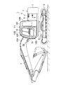
まず、図1ないし図6は本発明の第1の実施の形態を示している。図1において、1は第1の実施の形態に用いる建設機械としてのキャブ仕様の油圧ショベルで、該油圧ショベル1は、自走可能な下部走行体2と、該下部走行体2上に旋回可能に搭載され、該下部走行体2と共に車体を構成する上部旋回体3と、該上部旋回体3の前側に俯仰動可能に設けられ、土砂の掘削作業等を行なう作業装置4とにより大略構成されている。 First, FIG. 1 to FIG. 6 show a first embodiment of the present invention. In FIG. 1, reference numeral 1 denotes a cab specification hydraulic excavator as a construction machine used in the first embodiment. The hydraulic excavator 1 is capable of traveling on a self-propelled lower traveling body 2 and on the lower traveling body 2. The upper revolving structure 3 mounted on the upper revolving structure 2 and constituting the vehicle body together with the lower traveling structure 2 and the working device 4 provided on the front side of the upper revolving structure 3 so as to be able to be lifted and lowered and for performing excavation work of soil and the like. ing.
ここで、上部旋回体3は、例えば厚肉な鋼板等を用いて形成された旋回フレーム5と、該旋回フレーム5の後部側に搭載されたエンジン、油圧ポンプ(いずれも図示せず)等と、旋回フレーム5の右側から後側に亘って設けられ、燃料タンク、作動油タンク、ラジエータ、オイルクーラ(いずれも図示せず)、エンジン等を覆った外装カバー6と、前記旋回フレーム5の後端部に取付けられたカウンタウエイト7と、旋回フレーム5の左前側に搭載された後述のキャブ11とにより大略構成されている。
Here, the upper swing body 3 includes, for example, a swing frame 5 formed using a thick steel plate, an engine mounted on the rear side of the swing frame 5, a hydraulic pump (none of which is shown), and the like. An
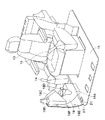
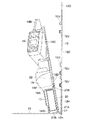
11は旋回フレーム5上の左前側に搭載された第1の実施の形態によるキャブで、該キャブ11は、オペレータが乗車して各種作業を行なうものである。そして、キャブ11は、図2、図3に示す如く、後述のキャブ本体12、運転席13、床板15、ダクトカバー18、カバーブラケット20、蝶番21等により大略構成されている。
12は旋回フレーム5上に複数個の防振マウント(図示せず)を介して設けられたキャブ本体で、該キャブ本体12は、内部に運転室を画成する中空構造体を構成している。そして、キャブ本体12は、図1、図2に示す如く、例えば前面部12A、後面部12B、左側面部12C、右側面部12D、天井面部12Eとにより箱体として形成されている。また、左側面部12Cには、前側寄りに位置してオペレータが乗り降りする乗降口12Fが設けられ、該乗降口12Fにはドア12Gが開閉可能に取付けられている。
一方、キャブ本体12の下端部には、図4、図5等に示すように、内側に屈曲して取付枠12Hが設けられている。そして、キャブ本体12は、例えば下側の四隅部分が防振マウントにボルト、ナット(いずれも図示せず)を介して取付けられている。また、取付枠12Hには、後述する床板15の周縁部分が複数本のボルト(図示せず)を用いて取付けられている。さらに、キャブ本体12の右側面部12Dには、前側に位置して例えば3個のねじ座12Jが設けられている。これらのねじ座12Jは、後述のカバーブラケット20を起立位置で固定するのに用いるものである。
On the other hand, at the lower end of the
13はキャブ本体12内のほぼ中央に位置して設けられた運転席で、該運転席13は、キャブ11に搭乗したオペレータが着座するもので、例えば後述の床板15上に設けられている。また、運転席13の左,右両側には、作業装置4等を操作するための作業レバー14,14が設けられている。
A driver's
15はキャブ本体12と一緒に各防振マウントに取付けられた床板で、該床板15は、図2、図3に示す如く、例えば前,後方向に長尺なほぼ長方形状の板体として形成され、キャブ本体12の下側を覆っている。また、床板15は、図5、図6に示すように、その周縁部分がキャブ本体12の取付枠12Hにボルト等(図示せず)を用いて取付けられている。さらに、床板15には、運転席13の前側に位置して下部走行体2を走行させるための走行レバー・ペダル(図示せず)が設けられている。また、床板15の右前側には、後述のカバーブラケット20が蝶番21を用いて取付けられている。
16は運転席13の後側に位置して床板15上に設けられた空調ユニット(図2中に点線で図示)で、該空調ユニット16は、キャブ11内に冷風、温風からなる調和空気を供給するための空調装置の室内機を構成するものである。
また、17は空調ユニット16からの調和空気をキャブ本体12内の前側に導く下流側の空調ダクト(図4ないし図6中に図示)示している。この空調ダクト17は、一端側が空調ユニット16に接続された上流側の空調ダクト(図示せず)に連通し、他端側がキャブ本体12の右側面部12Dに沿って前側に延び、後述するダクトカバー18の吹出口18Bに接続されている。
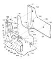
18はキャブ11内に位置して運転席13の右前側に設けられた内装品の1つとなるダクトカバーで、該ダクトカバー18は、キャブ本体12の乗降口12Fと左,右方向の反対側となる右側面部12D側に位置し、後述のカバーブラケット20、蝶番21を介して床板15に取付けられている。また、ダクトカバー18は、空調ダクト17を覆う機能と後述するモニタ装置19の取付台としての機能とを有している。
即ち、ダクトカバー18は、図3、図4に示すように、右作業レバー14の下側近傍位置から前方に延び、前側が上向きに湾曲したカバー本体部18Aと、該カバー本体部18Aの前端部(上端部)に設けられた吹出口18Bと、前記カバー本体部18Aの前側から後向きに突出するほぼ角筒状に形成されたモニタ取付部18Cと、前記カバー本体部18Aから上側に張出した上側張出部18Dと、前記カバー本体部18Aの前側に張出した前側張出部18Eとにより大略構成されている。また、ダクトカバー18には、例えば上側張出部18Dに上,下に間隔をもって2個のボルト穴18Fが設けられ、前側張出部18Eに上,中,下に3個のボルト穴18Fが設けられている。
That is, as shown in FIGS. 3 and 4, the
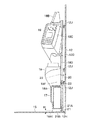
さらに、カバー本体部18Aは、図5に示す起立位置で、その下端部18A1が床板15よりも高さ寸法Hだけ高くなり、該床板15との間に隙間を有している。この高さ寸法Hの隙間は、後述のカバーブラケット20を転倒位置に倒すときに必要なものである。
Furthermore, the cover
19はダクトカバー18のモニタ取付部18Cに設けられた内装品としてのモニタ装置で、該モニタ装置19は、作業状態等の情報をオペレータに向け表示するもので、例えば水温計、燃料計、液晶表示部、各種ランプ等により構成されている。そして、モニタ装置19は、複数本のハーネスを介してコントローラ等(いずれも図示せず)に接続されている。
ここで、空調ダクト17、ダクトカバー18、モニタ装置19等は、油圧ショベル1で各種作業を行なう場合、作業環境を整え、作業状況を表示するのに必要な内装品を構成している。そして、内装品を構成する空調ダクト17、ダクトカバー18、モニタ装置19は、後述のカバーブラケット20と一緒にキャブ本体12の乗降口12Fと左,右方向の反対側に位置する右側面部12Dに近接して配置されている。
Here, the
20はキャブ本体12内に位置して床板15の右前側に設けられた内装品ブラケットとしてのカバーブラケットで、該カバーブラケット20は、キャブ本体12の右側面部12Dに対面する近接位置に配設され、後述の蝶番21を介して床板15に左,右方向に起倒可能に取付けられている。また、カバーブラケット20は、例えばダクトカバー18の外形形状にほぼ沿うように切出された板体として形成されている。さらに、カバーブラケット20には、図4に示すように、例えば2個のねじ穴20Aと3個のボルト挿通穴20Bとが形成されている。
21,21はカバーブラケット20を床板15に取付けるために前,後に離間して例えば2個設けられた蝶番で、該各蝶番21は、カバーブラケット20をキャブ本体12の右側面部12Dに対し接近、離間する方向に移動させるものである。また、各蝶番21は、一方の取付部21Aがカバーブラケット20の下端部にねじ止めされ、他方の取付部21Bが床板15にねじ止めされている。
そして、蝶番21は、図5に示すように、ダクトカバー18が取付けられたカバーブラケット20を、キャブ本体12の右側面部12Dに接近させて該右側面部12Dに沿って起立させた起立位置と、キャブ本体12の右側面部12Dから離れる左方向にダクトカバー18を倒し、図6に示すように、カバー本体部18Aの下端部18A1を床板15に当接させた転倒位置との間で起倒させることができる。
Then, as shown in FIG. 5, the
また、転倒位置では、キャブ本体12の右側面部12Dからカバーブラケット20を離間させて隙間を形成することができるから、キャブ本体12の取外し、取付け作業(交換作業)を行なうときに、キャブ本体12の取付枠12Hとカバーブラケット20とが干渉するのを防止することができる。さらに、蝶番21は、カバーブラケット20を再度起立位置に戻したときには交換前の元の位置に合わせることができる。
In the fall position, the
22はダクトカバー18をカバーブラケット20に取付ける例えば2本のボルトで、該各ボルト22は、ダクトカバー18の上側張出部18Dに設けられた上側のボルト穴18Fと前側張出部18Eに設けられた中央のボルト穴18Fとに装着され、カバーブラケット20の各ねじ穴20Aに螺着するものである。
また、23はダクトカバー18をカバーブラケット20と一緒にキャブ本体12の右側面部12Dに固定する例えば3本のボルトを示している。この3本のボルト23は、ダクトカバー18の上側張出部18Dに設けられた下側のボルト穴18F、前側張出部18Eに設けられた上側,下側のボルト穴18F,18Fと、カバーブラケット20の各ボルト挿通穴20Bとに挿通し、右側面部12Dに設けられたねじ座12Jに螺着することにより、ダクトカバー18とカバーブラケット20を起立位置に固定するものである。
一方、3本のボルト23を弛めたときには、ダクトカバー18がボルト22で取付けられたカバーブラケット20を右側面部12Dから切離し、蝶番21によって転倒位置に倒すことができる。
On the other hand, when the three
第1の実施の形態による油圧ショベル1のキャブ11は上述の如き構成を有するもので、次に、キャブ11を構成するキャブ本体12を他のキャブ(図示せず)に交換する場合の作業について説明する。
The
まず、旋回フレーム5からキャブ本体12だけを取外す。この場合には、ダクトカバー18と一緒にカバーブラケット20をキャブ本体12の右側面部12Dに固定している3本のボルト23を弛めて取外す。そして、カバーブラケット20を、ダクトカバー18、モニタ装置19等と一緒に蝶番21を中心として左側に倒すことにより、これらの内装品を転倒位置(図6に示す位置)に配置する。これにより、カバーブラケット20、ダクトカバー18等は、キャブ本体12の右側面部12Dから十分に離間させることができる。
First, only the
次に、キャブ本体12を防振マウントに固定しているナットを外し、取付枠12Hに床板15を取付けているボルトを取外す。この状態で、キャブ本体12を吊上げることにより、キャブ本体12の取付枠12Hがカバーブラケット20等に干渉しないようにキャブ本体12だけを取外すことができる。
Next, the nut that fixes the
そして、キャブ本体12を床板15から取外したら、キャブ本体12が損傷した場合には新しいキャブ本体12を、トンネル内で作業を行なう場合にはパイプキャブを、地下作業を行なう場合には低頭キャブを取付ける。この取付作業では、例えば新しいキャブ本体12を床板15の上側から降ろすことにより、取付枠12Hがカバーブラケット20等に干渉しないようにキャブ本体12を旋回フレーム5側に取付けることができる。
When the
また、キャブ本体12を旋回フレーム5に取付けたら、カバーブラケット20等を右側に起こすことにより、キャブ本体12の右側面部12Dに沿って起立する起立位置(図5に示す位置)に配置する。このときにカバーブラケット20は、蝶番21を中心に一定の円弧を描いて回動するから、カバーブラケット20を起立位置に配置したときには、キャブ本体12を取外す前と同じ位置に配置することができる。これにより、位置合わせ作業を行なうことなく3本のボルト23を簡単に螺着することができ、カバーブラケット20、ダクトカバー18、モニタ装置19をキャブ本体12の右側面部12Dに容易に固定することができる。
Further, when the
次に、上述のように構成された油圧ショベル1で作業を行なう場合の操作について説明する。 Next, the operation when working with the excavator 1 configured as described above will be described.
まず、ドア12Gを開いて乗降口12Fからキャブ本体12内に乗り込んで運転席13に着座したオペレータは、走行用レバー・ペダルを操作することにより、下部走行体2を走行させることができる。また、左,右の作業レバー14を操作することにより、作業装置4等を動作させ、土砂の掘削作業等を行うことができる。
First, an operator who opens the
この作業時には、ダクトカバー18に設けられたモニタ装置19をみることにより、水温、燃料残量等の情報を得ることができる。また、空調ユニット16を駆動することにより、ダクトカバー18の吹出口18Bから調和空気を吹出し、キャブ本体12内の作業環境を良好にすることができる。
During this operation, information such as the water temperature and the remaining amount of fuel can be obtained by looking at the
かくして、第1の実施の形態によれば、ダクトカバー18、モニタ装置19等は、床板15に設けたカバーブラケット20に取付ける構成としているから、運転席13、床板15、ダクトカバー18等を旋回フレーム5側に残してキャブ本体12だけを取外す場合でも、ダクトカバー18、モニタ装置19等を取外す必要がなく、キャブ本体12を防振マウントに固定しているナットを弛めるだけで、該キャブ本体12を簡単に取外すことができ、また取付けることもできる。
Thus, according to the first embodiment, the
この結果、キャブ本体12を新しいキャブ本体12に交換したり、作業内容に応じてパイプキャブ、低頭キャブ等に変更したりする場合でも、交換作業を容易に行なうことができ、作業性を向上することができる。
As a result, even when the
しかも、カバーブラケット20は、蝶番21を用いてキャブ本体12の右側面部12Dに対し接近、離間する方向に移動(起倒)させることができるから、カバーブラケット20を左側に倒した転倒位置では、キャブ本体12の右側面部12Dとカバーブラケット20との間の隙間を広げることができる。これにより、キャブ本体12を旋回フレーム5から取外したり、取付ける場合に、該キャブ本体12がカバーブラケット20等に干渉するのを防止でき、キャブ本体12の交換作業を安全かつ効率よく行なうことができる。
Moreover, since the
また、カバーブラケット20等は、蝶番21を中心に起倒するから、キャブ本体12を交換してカバーブラケット20等を起立位置に戻したときには、キャブ本体12を取外す前と同じ位置に配置することができる。これにより、位置合わせ作業を行なうことなく3本のボルト23を簡単に螺着することができ、より一層作業性を向上することができる。
Further, since the
特に、キャブ本体12の乗降口12Fから奥まった位置で手が届きにくい場所にダクトカバー18、モニタ装置19等が配置されている場合でも、このダクトカバー18、モニタ装置19および該モニタ装置19のハーネス等を取外す必要がないから、キャブ本体12の交換作業を容易に行なうことができる。
In particular, even when the
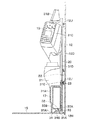
次に、図7および図8は本発明の第2の実施の形態を示している。本実施の形態の特徴は、内装品ブラケットを床板に2個以上の折曲部を有する多重折曲装置を用いて取付け、該多重折曲装置により内装品ブラケットは、キャブ本体を形成する側面部に沿って起立する起立位置とこの側面部から離れる方向に倒れる転倒位置との間で起倒させる構成としたことにある。なお、本実施の形態では、前述した第1の実施の形態と同一の構成要素に同一の符号を付し、その説明を省略するものとする。 Next, FIG. 7 and FIG. 8 show a second embodiment of the present invention. A feature of the present embodiment is that the interior product bracket is attached to the floor plate using a multiple folding device having two or more folded parts, and the interior product bracket forms a cab body by the multiple folding device. It is that it was set as the structure made to rise between the standing position which stands up along and the fall position which falls in the direction away from this side part. In the present embodiment, the same components as those in the first embodiment described above are denoted by the same reference numerals, and the description thereof is omitted.
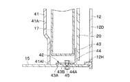
図7において、31は第2の実施の形態による内装品としてのダクトカバーで、該ダクトカバー31は、第1の実施の形態によるダクトカバー18とほぼ同様に、カバー本体部31A、吹出口31B、モニタ取付部31C、上側張出部31D、前側張出部(図示せず)、ボルト穴31Eによって大略構成されている。しかし、第2の実施の形態によるダクトカバー31は、カバー本体部31Aの下端部31A1が床板15に当接するまで下側に延びている点で、第1の実施の形態によるダクトカバー18と相違している。そして、ダクトカバー31は、カバー本体部31Aの下端部31A1が床板15に当接することにより、該床板15との隙間がなくなって外観上の見栄えが良好になる。
In FIG. 7,
32はカバーブラケット20と床板15との間に前,後方向に離間して2個設けられた多重折曲装置(後側のみ図示)を示している。この多重折曲装置32は、2個の蝶番33,34を上,下方向に重ねて連結することにより、2個の折曲部を有する構成となっている。また、多重折曲装置32は、上側に位置する蝶番33の一方の取付部33Aがカバーブラケット20の下端部にねじ止めされ、他方の取付部33Bが下側に位置する蝶番34の一方の取付部34Aに連結(固着)され、下側に位置する蝶番34の他方の取付部34Bが床板15にねじ止めされている。
そして、2個の蝶番33,34を連結した多重折曲装置32は、図7に示すように、ダクトカバー31が取付けられたカバーブラケット20を、キャブ本体12の右側面部12Dに接近させて該右側面部12Dに沿って起立させた起立位置と、キャブ本体12の右側面部12Dから離れる左方向にダクトカバー31を倒し、図8に示すように、カバー本体部31Aの下端部31A1を床板15に当接させた転倒位置との間で起倒させることができる。
Then, as shown in FIG. 7, the
ここで、多重折曲装置32は、2個の蝶番33,34を重ねて連結することにより、2個の折曲部によってダクトカバー31、カバーブラケット20を上側にも移動することができるから、第1の実施の形態でダクトカバー18のカバー本体部18Aと床板15との間に形成していた隙間を必要とせず、ダクトカバー31を床板15に当接させた状態で設けることができる。
Here, the
かくして、このように構成された第2の実施の形態によれば、前述した第1の実施の形態とほぼ同様の作用効果を得ることができる。特に、第2の実施の形態では、2個の蝶番33,34を連結して多重折曲装置32を構成しているから、該多重折曲装置32は、ダクトカバー31、カバーブラケット20等を上側にも移動することができる。この結果、ダクトカバー31を床板15に当接させた状態で設けることができ、隙間を無くして外観上の見栄えを良好にすることができる。
Thus, according to the second embodiment configured in this way, it is possible to obtain substantially the same operational effects as those of the first embodiment described above. In particular, in the second embodiment, since the
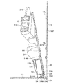
次に、図9ないし図11は本発明の第3の実施の形態を示している。本実施の形態の特徴は、内装品ブラケットを床板にスライド装置を用いて取付け、該スライド装置により内装品ブラケットは、キャブ本体を形成する側面部に接近した接近位置とこの側面部から離間した離間位置との間でスライド移動させる構成としたことにある。なお、本実施の形態では、前述した第1の実施の形態と同一の構成要素に同一の符号を付し、その説明を省略するものとする。 Next, FIGS. 9 to 11 show a third embodiment of the present invention. The feature of the present embodiment is that the interior product bracket is attached to the floor board using a slide device, and the slide device causes the interior product bracket to be close to the side surface forming the cab body and spaced apart from the side surface. The configuration is such that the slide movement is performed between the positions. In the present embodiment, the same components as those in the first embodiment described above are denoted by the same reference numerals, and the description thereof is omitted.
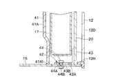
図9において、41は第3の実施の形態による内装品としてのダクトカバーで、該ダクトカバー41は、第1の実施の形態によるダクトカバー18とほぼ同様に、カバー本体部41A、吹出口41B、モニタ取付部41C、上側張出部41D、前側張出部(図示せず)、ボルト穴41Eによって大略構成されている。しかし、第3の実施の形態によるダクトカバー41は、カバー本体部41Aの下端部41A1が床板15に当接するまで下側に延びている点で、第1の実施の形態によるダクトカバー18と相違している。そして、ダクトカバー41は、カバー本体部41Aの下端部41A1が床板15に当接することにより、該床板15との隙間がなくなって外観上の見栄えが良好になる。
In FIG. 9,
42はカバーブラケット20と床板15との間に前,後方向に離間して2箇所に設けられたスライド装置(後側のみ図示)で、該各スライド装置42は、図10、図11に示すように、カバーブラケット20の下端部に固着され、床板15との当接部43Aに左,右方向に延びる長穴43Bが形成されたスライド部材43と、該スライド部材43の長穴43Bにスペーサ44Aを介して係合し、床板15に取付けられたボルト44およびナット45とにより構成されている。
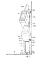
そして、スライド装置42は、ダクトカバー41が取付けられたカバーブラケット20を、キャブ本体12の右側面部12Dに設けられたねじ座12Jに当接させた接近位置(図9、図10に示す位置)と、この接近位置からスライド部材43の長穴43Bに沿って左側にスライドさせてキャブ本体12の右側面部12Dから離間した離間位置(図11に示す位置)とに移動することができる。
Then, the
ここで、スライド装置42は、ダクトカバー41、カバーブラケット20等をスライドして移動させているから、第1の実施の形態でダクトカバー18のカバー本体部18Aと床板15との間に形成していた隙間を必要とせず、ダクトカバー41を床板15に当接させた状態で設けることができる。
Here, since the
かくして、このように構成された第3の実施の形態においても、前述した各実施の形態とほぼ同様の作用効果を得ることができる。 Thus, also in the third embodiment configured as described above, it is possible to obtain substantially the same operational effects as those of the above-described embodiments.
なお、第1の実施の形態では、カバーブラケット20と蝶番21とを別体に設け、該蝶番21の一方の取付部21Aをカバーブラケット20にねじ止めし、他方の取付部21Bを床板15にねじ止めする構成とした場合を例に挙げて説明した。しかし、本発明はこれに限らず、例えばカバーブラケットの下端部に蝶番の一方の取付部に相当する構成を設け、床板に蝶番の他方の取付部に相当する構成を設け、両者を回動可能に連結する構成としてもよい。
In the first embodiment, the
また、第1の実施の形態では、蝶番21を前,後方向に離間して2個設けた場合を例に挙げて説明した。しかし、本発明はこれに限るものではなく、例えば蝶番21を1個または3個以上設ける構成としてもよい。この構成は第2、第3の実施の形態にも同様に適用することができる。 Further, in the first embodiment, the case where two hinges 21 are provided apart in the front and rear directions has been described as an example. However, the present invention is not limited to this. For example, one or three or more hinges 21 may be provided. This configuration can be similarly applied to the second and third embodiments.
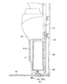
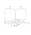
一方、第3の実施の形態では、スライド装置42は、カバーブラケット20に固着され床板15との当接部43Aに長穴43Bを有するたスライド部材43と、該スライド部材43の長穴43Bにスペーサ44Aを介して係合し床板15に取付けられたボルト44およびナット45とにより構成した。しかし、本発明はこれに限らず、例えば図12、図13に示す変形例のように、スライド装置51は、カバーブラケット20の下端部から床板15に当接して左方向に延びる当接部52Aを有するスライド部材52と、該スライド部材52の当接部52Aを上側から押えつつ前,後方向から挟むように床板15に取付けられた前,後のガイド部材53(後側のみ図示)とによって構成してもよい。
On the other hand, in the third embodiment, the
また、各実施の形態では、床板15はキャブ本体12の下側を覆う状態で設けるものとして説明した。しかし、本発明はこれに限らず、例えば運転席の前側だけに床板を設ける構成としてもよい。
Moreover, in each embodiment, the
さらに、各実施の形態では、建設機械として油圧ショベル1を例示した。しかし、本発明はこれに限るものではなく、例えば油圧クレーン、ホイールローダ、リフトトラック等の他の建設機械にも広く適用することができる。 Furthermore, in each embodiment, the hydraulic excavator 1 was illustrated as a construction machine. However, the present invention is not limited to this, and can be widely applied to other construction machines such as a hydraulic crane, a wheel loader, and a lift truck.
1 油圧ショベル(建設機械)
2 下部走行体
3 上部旋回体
4 作業装置
5 旋回フレーム
11 キャブ
12 キャブ本体
12A 前面部
12B 後面部
12C 左側面部
12D 右側面部
12E 天井面部
12F 乗降口
13 運転席
15 床板
16 空調ユニット(内装品)
17 空調ダクト(内装品)
18,31,41 ダクトカバー(内装品)
19 モニタ装置(内装品)
20 カバーブラケット(内装品ブラケット)
21 蝶番
32 多重折曲装置
42,51 スライド装置
1 Excavator (construction machine)
DESCRIPTION OF SYMBOLS 2 Lower traveling body 3 Upper revolving body 4 Working apparatus 5
17 Air conditioning duct (interior)
18, 31, 41 Duct cover (interior)
19 Monitor device (interior)
20 Cover bracket (interior bracket)
21
Claims (6)
前記キャブ本体内には、前記内装品を取付ける内装品ブラケットを前記床板に設ける構成としたことを特徴とする建設機械用キャブ。 A hollow cab body that is provided on the frame of the construction machine and defines a driver's cab inside, a driver seat that is provided in the cab body and seated by an operator, and at least a front portion of the driver seat. A cab for a construction machine, comprising: a floor plate, and an interior part provided in the cab body around the driver seat;
A construction machine cab characterized in that an interior product bracket for mounting the interior product is provided on the floor plate in the cab body.
Priority Applications (1)
| Application Number | Priority Date | Filing Date | Title |
|---|---|---|---|
| JP2004111267A JP4303156B2 (en) | 2004-04-05 | 2004-04-05 | Construction machinery cab |
Applications Claiming Priority (1)
| Application Number | Priority Date | Filing Date | Title |
|---|---|---|---|
| JP2004111267A JP4303156B2 (en) | 2004-04-05 | 2004-04-05 | Construction machinery cab |
Publications (2)
| Publication Number | Publication Date |
|---|---|
| JP2005290928A true JP2005290928A (en) | 2005-10-20 |
| JP4303156B2 JP4303156B2 (en) | 2009-07-29 |
Family
ID=35324168
Family Applications (1)
| Application Number | Title | Priority Date | Filing Date |
|---|---|---|---|
| JP2004111267A Expired - Fee Related JP4303156B2 (en) | 2004-04-05 | 2004-04-05 | Construction machinery cab |
Country Status (1)
| Country | Link |
|---|---|
| JP (1) | JP4303156B2 (en) |
Cited By (6)
| Publication number | Priority date | Publication date | Assignee | Title |
|---|---|---|---|---|
| JP2007154453A (en) * | 2005-12-01 | 2007-06-21 | Komatsu Ltd | Construction machine rear console mounting structure |
| JP2012136830A (en) * | 2010-12-24 | 2012-07-19 | Komatsu Ltd | Construction machine |
| JP2012136829A (en) * | 2010-12-24 | 2012-07-19 | Komatsu Ltd | Construction machine |
| JP2014031687A (en) * | 2012-08-06 | 2014-02-20 | Kubota Corp | Work machine |
| JP2014031688A (en) * | 2012-08-06 | 2014-02-20 | Kubota Corp | Work machine |
| JP5567229B1 (en) * | 2013-05-08 | 2014-08-06 | 株式会社小松製作所 | Work vehicle |
-
2004
- 2004-04-05 JP JP2004111267A patent/JP4303156B2/en not_active Expired - Fee Related
Cited By (8)
| Publication number | Priority date | Publication date | Assignee | Title |
|---|---|---|---|---|
| JP2007154453A (en) * | 2005-12-01 | 2007-06-21 | Komatsu Ltd | Construction machine rear console mounting structure |
| JP2012136830A (en) * | 2010-12-24 | 2012-07-19 | Komatsu Ltd | Construction machine |
| JP2012136829A (en) * | 2010-12-24 | 2012-07-19 | Komatsu Ltd | Construction machine |
| JP2014031687A (en) * | 2012-08-06 | 2014-02-20 | Kubota Corp | Work machine |
| JP2014031688A (en) * | 2012-08-06 | 2014-02-20 | Kubota Corp | Work machine |
| JP5567229B1 (en) * | 2013-05-08 | 2014-08-06 | 株式会社小松製作所 | Work vehicle |
| WO2014181392A1 (en) * | 2013-05-08 | 2014-11-13 | 株式会社小松製作所 | Work vehicle |
| US9284716B2 (en) | 2013-05-08 | 2016-03-15 | Komatsu Ltd. | Work vehicle |
Also Published As
| Publication number | Publication date |
|---|---|
| JP4303156B2 (en) | 2009-07-29 |
Similar Documents
| Publication | Publication Date | Title |
|---|---|---|
| US11866101B2 (en) | Working machine | |
| US8038202B2 (en) | Operators section construction for work vehicle | |
| JP5918072B2 (en) | Working machine | |
| KR102715232B1 (en) | Driver's cab for power machinery | |
| CN113891974B (en) | Working machine | |
| JP4057542B2 (en) | Construction machinery | |
| CN104631539A (en) | Construction machine | |
| JP6213526B2 (en) | Work machine | |
| JP6003957B2 (en) | Interior arrangement structure of construction machinery | |
| JP4303156B2 (en) | Construction machinery cab | |
| US20060185200A1 (en) | Rear end small revolving type hydraulic shovel | |
| JP4274562B2 (en) | Maintenance structure in construction machinery | |
| JP4347730B2 (en) | Construction machinery | |
| JP2007092278A (en) | Backhoe superstructure | |
| JPH09268597A (en) | Drive unit structure of backhoe | |
| JP4877903B2 (en) | Work vehicle | |
| JP4381364B2 (en) | Backhoe | |
| JP4703334B2 (en) | Backhoe | |
| JP2005112049A (en) | Engine room cover device | |
| JP4447516B2 (en) | Tractor | |
| JPH093972A (en) | Airframe structure of work machine | |
| JP2009068172A (en) | Controller arrangement structure of working machine | |
| JP2005213816A (en) | Work machine seat mounting device | |
| JP2007092326A (en) | Backhoe | |
| KR20150035357A (en) | Head-feeding combine, combine and working vehicle |
Legal Events
| Date | Code | Title | Description |
|---|---|---|---|
| A621 | Written request for application examination |
Effective date: 20060529 Free format text: JAPANESE INTERMEDIATE CODE: A621 |
|
| A977 | Report on retrieval |
Effective date: 20080725 Free format text: JAPANESE INTERMEDIATE CODE: A971007 |
|
| A131 | Notification of reasons for refusal |
Free format text: JAPANESE INTERMEDIATE CODE: A131 Effective date: 20080819 |
|
| A521 | Written amendment |
Effective date: 20081017 Free format text: JAPANESE INTERMEDIATE CODE: A523 |
|
| TRDD | Decision of grant or rejection written | ||
| A01 | Written decision to grant a patent or to grant a registration (utility model) |
Effective date: 20090421 Free format text: JAPANESE INTERMEDIATE CODE: A01 |
|
| A01 | Written decision to grant a patent or to grant a registration (utility model) |
Free format text: JAPANESE INTERMEDIATE CODE: A01 |
|
| A61 | First payment of annual fees (during grant procedure) |
Effective date: 20090423 Free format text: JAPANESE INTERMEDIATE CODE: A61 |
|
| FPAY | Renewal fee payment (prs date is renewal date of database) |
Year of fee payment: 3 Free format text: PAYMENT UNTIL: 20120501 |
|
| R150 | Certificate of patent (=grant) or registration of utility model |
Free format text: JAPANESE INTERMEDIATE CODE: R150 |
|
| LAPS | Cancellation because of no payment of annual fees |