JP2005290927A - Cabin door opening and closing device for work vehicle - Google Patents
Cabin door opening and closing device for work vehicle Download PDFInfo
- Publication number
- JP2005290927A JP2005290927A JP2004111263A JP2004111263A JP2005290927A JP 2005290927 A JP2005290927 A JP 2005290927A JP 2004111263 A JP2004111263 A JP 2004111263A JP 2004111263 A JP2004111263 A JP 2004111263A JP 2005290927 A JP2005290927 A JP 2005290927A
- Authority
- JP
- Japan
- Prior art keywords
- opening
- door
- closing
- cabin
- damper
- Prior art date
- Legal status (The legal status is an assumption and is not a legal conclusion. Google has not performed a legal analysis and makes no representation as to the accuracy of the status listed.)
- Pending
Links
Images


Landscapes
- Body Structure For Vehicles (AREA)
Abstract
【課題】 従来の開閉ダンパ−はドアの窓ガラス対応面内に配置されているため、これが邪魔になり、視界性を悪くする問題があった。
この発明は、従来型のもつ課題を解決し、円滑に開閉作動するドア開閉装置を具現することにある。
【解決手段】 本発明の特徴とするキャビンドア開閉装置は、キャビン支持フレ−ム11に対しヒンジ12周りに揺動開閉可能に設けられたキャビンドア9と、該ドアの開閉作動に伴い揺動変位する開閉ア−ム20に保持されたカムロ−ラ21と、前記キャビンドア9側に装着されて前記カムロ−ラ21を接当案内する開閉カム体22と、前記ヒンジ部を外装する外装カバ−枠23内に内装されて前記カムロ−ラ21を開閉カム体22側に向けて弾発保持させる開閉ダンパ−24とからなる。
【選択図】 図2PROBLEM TO BE SOLVED: There is a problem that a conventional opening / closing damper is disposed in a window glass-corresponding surface of a door, which becomes an obstacle and deteriorates visibility.
An object of the present invention is to solve the problems of the conventional type and to implement a door opening / closing device that smoothly opens and closes.
A cabin door opening and closing device characterized by the present invention includes a cabin door 9 that is swingably opened and closed around a hinge 12 with respect to a cabin support frame 11, and swings when the door is opened and closed. A cam roller 21 held by a displacing opening / closing arm 20, an opening / closing cam body 22 mounted on the cabin door 9 side for guiding the cam roller 21, and an exterior cover for covering the hinge portion. An opening / closing damper 24 is provided in the frame 23 and elastically holds the cam roller 21 toward the opening / closing cam body 22 side.
[Selection] Figure 2
Description
この発明は、トラクタのような作業車両におけるキャビンのドア開閉装置に関する。 The present invention relates to a cabin door opening and closing device in a work vehicle such as a tractor.
従来、キャビンドアを開放状態及び閉鎖状態に保持する開閉ダンパ−は、特許文献1にも示されているように、ドアの側方にはみ出した状態に配置されたものが多く一般的構成として知られている。
特に、従来の開閉ダンパ−はドアの窓ガラス対応面内に配置されているため、これが邪魔になり、視界性を悪くする問題があった。 In particular, since the conventional open / close damper is disposed in the window glass-corresponding surface of the door, there is a problem that this becomes an obstacle and deteriorates visibility.
この発明は、上記した従来型のもつ課題を解決するために、次のような技術的手段を講じた。 The present invention has taken the following technical means in order to solve the problems of the conventional type.
すなわち、請求項1記載の本発明の特徴とするキャビンドア開閉装置は、キャビン支持フレ−ム11に対しヒンジ12周りに揺動開閉可能に設けられたキャビンドア9と、該ドアの開閉作動に伴い揺動変位する開閉ア−ム20に保持されたカムロ−ラ21と、前記キャビンドア9側に装着されて前記カムロ−ラ21を接当案内する開閉カム体22と、前記ヒンジ部を外装する外装カバ−枠23内に内装されて前記カムロ−ラ21を開閉カム体22側に向けて弾発保持させる開閉ダンパ−24とからなる構成である。
In other words, the cabin door opening / closing device according to the first aspect of the present invention includes a
キャビンドアの開閉に際し、該ドアの開閉作動に伴い揺動変位する開閉ア−ム20のカムロ−ラ21が、開閉ダンパ−24を介して開閉カム体22のカム面に弾発された状態で案内移動される。開閉ダンパ−24はヒンジ部の外装カバ−枠23内に装填する構成であるため、これが邪魔になって視界を妨げることがなく、視界性を良好にする。しかも、ドアの開閉機構はカムロ−ラ21と開閉カム体22を利用した構成であるため、開閉作動が安定し、スム−ズに行える。
When the cabin door is opened and closed, the
請求項2記載の本発明は、請求項1において、前記開閉カム体22には、ドア開放時におけるカムロ−ラ21の位置決め用係合凹部25を設けてあることを特徴とする。
According to a second aspect of the present invention, in the first aspect, the opening /
ドア開放時には、カムロ−ラ21が開閉カム体22の係合凹部25に落ち込んで係止されることになり、ドア開放時の位置決めが的確に保持される。これにより、開放されたドアが誤って閉まるようなこともない。ドアの開放後のガタ付きも生じない。
When the door is opened, the
以上要するに、請求項1の本発明によれば、特に、ドアの開閉ダンパ−24がヒンジ部の外装カバ−枠23内に内装されているので、ドア側方にはみ出し状態に配置されものに比べて邪魔にならず、視界性が良くなる。また、ドアの開閉機構は上記開閉ダンパ−24に加えてカムロ−ラ21と開閉カム体22を利用した構成であるため、ドアの開閉作動が安定しスム−ズに行える効果がある。
In short, according to the first aspect of the present invention, since the door opening /
請求項2の本発明によれば、請求項1の発明効果を奏するものでありながら、ドア閉鎖時には、カムロ−ラ21が開閉カム体22の係合凹部25に落ち込んで係止されることになるので、ドア開放時の位置決めが的確に保持される。
According to the second aspect of the present invention, the
この発明の実施例を図面に基づき説明する。 An embodiment of the present invention will be described with reference to the drawings.
作業車両の一例であるトラクタ1は、走行車体2の前後に走行装置としての左右一対の車輪3,3及び走行クロ−ラ4,4が架設され、車体2上前部に操作ボックス5及びステアリングハンドル6等を有する操縦装置や、後部に運転席Sが設置されている。前記走行クロ−ラ4にはエンジンEからの回転動力が伝達されるようになっている。トラクタ1の後部には作業機としてロ−タリ耕耘装置7が昇降可能に装備されている。
A tractor 1, which is an example of a work vehicle, has a pair of left and
キャビン8は、前記操作ボックス5やステアリングハンドル6等からなる操縦装置や運転席Sを包囲する構成であり、左右の乗降口にキャビンドア9を有し、このキャビンドア9のドア枠10とキャビン支持フレ−ム11とがヒンジ12を介して連結され、ヒンジピン12P(図2)を回動支点として内外方向に揺動開閉する構成としている。なお、ヒンジ12の一方側のヒンジプレ−トはドア9のドア枠10に装着され、他方側のヒンジプレ−トはキャビン支持フレ−ム11に連結される。
The cabin 8 is configured to surround the control device including the operation box 5 and the
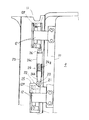
そして、該キャビンドア9の揺動開閉機構は、このドア9の開閉作動に伴い揺動変位する開閉ア−ム20に保持されたカムロ−ラ21と、前記キャビンドア9側に装着されて前記カムロ−ラ21を接当案内する開閉カム体22と、前記ヒンジ12部を外装する外装カバ−枠23内に内装されて前記カムロ−ラ21を開閉カム体22側に向けて弾発保持させる開閉ダンパ−24とからなる構成になっている。
A swing opening / closing mechanism of the
開閉ア−ム20は、ヒンジピン12P周りに揺動変位するようドア9側から内向きに突設し、かつ、外装カバ−枠23内からキャビン室内側に突出して揺動変位する構成としている。また、この開閉ア−ム20は先端のカムロ−ラ21と共に上下動変位可能であり、前記開閉ダンパ−24によって下向に弾発付勢されている。
The open /
開閉カム体22のカム形状は、ドア9を閉鎖する側において前記開閉ダンパ−24による弾発力が弱くなる略水平カム面T1又は緩勾配面とし、ドア9を開放する側においてはダンパ−の弾発力が次第に強くなる急勾配カム面T2としている。そして、該カム体22のドア開放側におけるカム面上には前記カムロ−ラ21の位置決め用係合凹部25を設けた構成としている。これにより、ドア開放後はカムロ−ラ21が係合凹部25に落ち込んで係合保持されて、開放後の位置決めが的確となる。
The cam shape of the opening /
開閉ダンパ−24は、スプリング24aと押圧摺動杆24bとこれらを内装保持する保持ケ−ス24c等からなり、上端が外装カバ−枠23にピン26により枢着され、下端側の押圧摺動杆24bがカムロ−ラ21を開閉カム体22のカム面に向けて弾圧付勢するようになっている。なお、開閉ダンパ−24はガスダンパ−やエアダンパ−であってもよい。
The open /
図5に示す実施例について説明すると、トラクタ後部の油圧シリンダケ−ス50にはリフトア−ム51が回動自在に枢着され、油圧シリンダケ−ス50内の油圧シリンダ内に作動油を供給するとリフトア−ム51が上昇回動し、排出するとリフトア−ム51は下降するようになっている。リフトア−ム51とロアリンク52とはリフトロッド53で連結され、そして、該ロアリンク52とトップリンク54には、作業機としてロ−タリ耕耘装置7が連結され、前記リフトア−ム51の昇降駆動によって上下動する構成となっている。
Referring to the embodiment shown in FIG. 5, a
そして、前記リフトア−ム51の近傍には少なくとも左右のフェンダ−間の幅をもつ布体や弾性体等からなる泥飛散防止プレ−ト55を設けている。この泥飛散防止プレ−ト55は、前記ロワ−リンク52の上下動に伴いこれと略平行移動するよう前記リフトア−ム51に連結された回動ア−ム56と前記ロアリンク52に連結のリンク57とで連結し、耕耘時には泥飛散防止プレ−ト55が地面に略平行するように遮蔽して運転席側への泥飛散を防止し、ロ−タリ耕耘装置7の上昇時(非作業時)は視界の妨げにならないよう運転席Sの背部近傍に収納位置させる構成としている。図5において実線はロータリ耕耘装置7等が下降位置にある状態、仮想線は上昇位置にある状態を示している。
In the vicinity of the
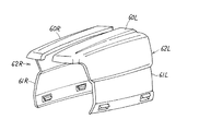
図6及び図7に示す実施例では、トラクタ前部のボンネット60を中央部から左右に分割して60L,60Rとし、左右のサイドカバ−61L,61Rと一体化して左右逆L型ボンネットカバ−62Lと62Rとし、これら両者をつき合せて取り付けたり、左右それぞれ単独に外側方へ取り外しできる構成としている。かかる構成によれば、エンジンやラジエ−タ部を大きく開放することができてメンテナンスが容易になる。また、中央部にカバ−の合せラインができるため、このラインがセンタ−マスコットの役目を果たすこともできる。
In the embodiment shown in FIGS. 6 and 7, the
次に、キャビンの振動を吸収するエアダンパ−構成における制御機構について説明する。 Next, a control mechanism in an air damper configuration that absorbs cabin vibration will be described.
図8において、コントロ−ラ30の入力側にエンジンの始動停止を検出するエンジン始動停止センサ31を接続して設け、コントロ−ラ30の出力側にはキャビンの振動を吸収するエアダンパ−32を圧力制御可能に設けている。なお、このエアダンパ−32は、車体前部の左右(左右前輪近く)と車体後部の左右(左右後輪近く)とにそれぞれ設けておくとよい。あるいは、従来、キャビンとミッションケースとの間に介装されていた防振ゴムの取付部にエアダンパー32を設けてもよい。
In FIG. 8, an engine start /
エンジンを始動(キ−スイッチON、エンジン回転スタ−ト)すると、エンジン始動停止センサ31により、エンジン始動を検出した時には、エアダンパ−32に圧を立てて予め設定された振動減衰値が最適となる圧力まで制御する。
When the engine is started (key switch ON, engine rotation start), when the engine start is detected by the engine start /
また、エンジン停止時は、エンジン回転「0」を感知してエアダンパ−圧力を静圧に保持する。つまり、エンジンを停止(キ−スイッチOFF、エンジン回転停止)すると、エンジン始動停止センサ31により、エンジン停止を検出した時にはエアダンパ−32に圧を立てて圧力制御を終了する。
Further, when the engine is stopped, the engine rotation “0” is detected and the air damper pressure is held at a static pressure. That is, when the engine is stopped (key switch OFF, engine rotation stop), when engine stop is detected by the engine start /
更に、前記コントロ−ラ30の入力側には、車体の走行速度を検出する車速センサ33を設け、車速に応じてエアダンパ−32のダンパ−圧を制御し、走行振動及びキャビン振動の低減を図るようにしている。
Further, a
走行車輪の近傍に車輪振動センサを設けて、走行時における車輪の振動を検出するようにし、車輪ラグの共振点に併せてダンパ圧を制御することによって、キャビンの振動を抑制することも容易にできる。この振動センサは直接車輪の振動をピックアップするのでセンシングが正確であり、ダンパ圧制御を容易にすることができる。なお、この制御は、図8に示すように、車輪振動センサ34をコントロ−ラ30の入力側に設け、該センサの振動検出結果に基づき、コントロ−ラ30を介してダンパ−32を制御するものである。
It is also easy to suppress the vibration of the cabin by providing a wheel vibration sensor in the vicinity of the traveling wheel so as to detect the vibration of the wheel during traveling and controlling the damper pressure in accordance with the resonance point of the wheel lug. it can. Since this vibration sensor directly picks up the vibration of the wheel, sensing is accurate and damper pressure control can be facilitated. In this control, as shown in FIG. 8, a
トラクタが傾斜走行するときは、車体の傾斜角を検出する傾斜センサでその傾きを検出し、傾斜下位側のダンパ−圧を高くしてキャビンの傾斜を抑制することもできる。 When the tractor is inclined, the inclination can be detected by an inclination sensor that detects the inclination angle of the vehicle body, and the damper pressure on the lower side of the inclination can be increased to suppress the inclination of the cabin.
トラクタの前後進時、レバ−操作に伴う発進時にキャビンの前後方向の揺れを少なくするため、前進時は後部側のダンパ圧を、後進時は前部側のダンパ圧を適正圧にコントロ−ルしてキャビンの傾きを抑制する。つまり、車体の前後進を切り換える操作レバ−36の基部に前進スイッチと後進スイッチを設ける。そして、図9に示すように、操作レバ−36により前進スイッチ37がONで発進操作があったときには、エアダンパ−32における後部ダンパ−32Rのダンパ圧を高くしてキャビンの傾斜を低減する。また、後進スイッチ38がONで発進操作があったときには、前部ダンパ−32Fのダンパ圧を高くしてキャビンの傾斜を低減する。
When the tractor is moving forward or backward, the rear damper pressure is controlled to an appropriate pressure when moving forward, and the front damper pressure is adjusted when moving backward, in order to reduce the forward and backward movement of the cabin when starting with the lever operation. To suppress cabin tilt. In other words, a forward switch and a reverse switch are provided at the base of the
なお、別実施例として、キャビン搭載時の振動を測定し、共振回転数域ではダンパ圧力を最適圧にコントロ−ルし、ピ−ク振動を回避する制御を行うこともできる。 As another embodiment, it is also possible to measure the vibration when the cabin is mounted, and to control the damper pressure to the optimum pressure in the resonance rotational speed range so as to avoid the peak vibration.
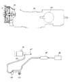
図10に示す実施例について説明すると、走行ミッションケ−スMcにはエンジンEの出力軸から後輪差動機構60までの走行動力伝達機構が内装されている。このミッションケ−スMc前部でエンジン本体とドッキングしたフロントミッションケ−ス内部の入力軸41には、エアダンパ−32にアキュムレ−タ42を介してエアを圧送するためのカム軸43と、エンジン回転と同時回転するエアポンプ(ダイヤフラムポンプ)44を構成して設けている。そして、このエアポンプ44には、該エアポンプ44への吸気パイプ45をエアクリ−ナ46からエンジンEへの配管47経路途中に接続して前記エアクリ−ナ46からのエアを吸入することにより、常に清浄なエアを取り入れることができ、ゴミの吸気のない構成とすることができる。
Referring to the embodiment shown in FIG. 10, the traveling mission case Mc is internally provided with a traveling power transmission mechanism from the output shaft of the engine E to the rear
8 キャビン 9 キャビンドア
10 ドア枠 11 キャビン支持フレ−ム
12 ヒンジ 20 開閉ア−ム
21 カムロ−ラ 22 開閉カム体
23 外装カバ−枠 24 開閉ダンパ−
25 位置決め用係合凹部
8
25 Engaging recess for positioning
Claims (2)
Priority Applications (1)
| Application Number | Priority Date | Filing Date | Title |
|---|---|---|---|
| JP2004111263A JP2005290927A (en) | 2004-04-05 | 2004-04-05 | Cabin door opening and closing device for work vehicle |
Applications Claiming Priority (1)
| Application Number | Priority Date | Filing Date | Title |
|---|---|---|---|
| JP2004111263A JP2005290927A (en) | 2004-04-05 | 2004-04-05 | Cabin door opening and closing device for work vehicle |
Publications (1)
| Publication Number | Publication Date |
|---|---|
| JP2005290927A true JP2005290927A (en) | 2005-10-20 |
Family
ID=35324167
Family Applications (1)
| Application Number | Title | Priority Date | Filing Date |
|---|---|---|---|
| JP2004111263A Pending JP2005290927A (en) | 2004-04-05 | 2004-04-05 | Cabin door opening and closing device for work vehicle |
Country Status (1)
| Country | Link |
|---|---|
| JP (1) | JP2005290927A (en) |
Cited By (1)
| Publication number | Priority date | Publication date | Assignee | Title |
|---|---|---|---|---|
| KR101672163B1 (en) * | 2016-03-11 | 2016-11-02 | 주식회사 삼흥정밀 | Door with a damping function for opening and closing the upper and lower cabinets |
-
2004
- 2004-04-05 JP JP2004111263A patent/JP2005290927A/en active Pending
Cited By (1)
| Publication number | Priority date | Publication date | Assignee | Title |
|---|---|---|---|---|
| KR101672163B1 (en) * | 2016-03-11 | 2016-11-02 | 주식회사 삼흥정밀 | Door with a damping function for opening and closing the upper and lower cabinets |
Similar Documents
| Publication | Publication Date | Title |
|---|---|---|
| US7841639B2 (en) | Utility vehicle equipped with extendable cargo bed | |
| JP7049921B2 (en) | Work machine cab, and work machine | |
| US11660941B2 (en) | Cab for work machine, work machine, and automatic opening/closing device | |
| JP3018959B2 (en) | Wiper operation control device for construction machinery | |
| JP2005290927A (en) | Cabin door opening and closing device for work vehicle | |
| JP2742904B2 (en) | Storage structure of control unit in field work machine | |
| JP4686877B2 (en) | Vehicle cockpit structure | |
| JP5094649B2 (en) | Loader working machine | |
| JP4283600B2 (en) | Opening and closing device for vehicle opening and closing body | |
| JP5016572B2 (en) | Loader working machine | |
| WO2022173395A1 (en) | Joystick anti-hitting seat steering mechanism for work machines | |
| JP5119094B2 (en) | Loader working machine | |
| JP4909780B2 (en) | Front spoiler device | |
| JP2005162034A (en) | Interference prevention mechanism during cabylt | |
| JP6076522B1 (en) | Vehicle with handle cover | |
| JP7162566B2 (en) | work vehicle | |
| JP2010059684A5 (en) | ||
| JP2010059683A5 (en) | ||
| JP5248793B2 (en) | Work vehicle | |
| JP7237035B2 (en) | construction machinery | |
| JP4685275B2 (en) | Side door for work vehicle driving cabin | |
| WO2018235523A1 (en) | Motor grader | |
| JP5094650B2 (en) | Loader working machine | |
| JPS5918904Y2 (en) | Industrial vehicle control lever mounting device | |
| JP4044403B2 (en) | Traveling vehicle |