JP2005290905A - Portable machine case structure - Google Patents
Portable machine case structure Download PDFInfo
- Publication number
- JP2005290905A JP2005290905A JP2004110193A JP2004110193A JP2005290905A JP 2005290905 A JP2005290905 A JP 2005290905A JP 2004110193 A JP2004110193 A JP 2004110193A JP 2004110193 A JP2004110193 A JP 2004110193A JP 2005290905 A JP2005290905 A JP 2005290905A
- Authority
- JP
- Japan
- Prior art keywords
- case
- sandwiched
- locking
- mechanical key
- sandwiching
- Prior art date
- Legal status (The legal status is an assumption and is not a legal conclusion. Google has not performed a legal analysis and makes no representation as to the accuracy of the status listed.)
- Pending
Links
Images
Classifications
-
- A—HUMAN NECESSITIES
- A45—HAND OR TRAVELLING ARTICLES
- A45C—PURSES; LUGGAGE; HAND CARRIED BAGS
- A45C11/00—Receptacles for purposes not provided for in groups A45C1/00-A45C9/00
- A45C11/32—Bags or wallets for holding keys
-
- Y—GENERAL TAGGING OF NEW TECHNOLOGICAL DEVELOPMENTS; GENERAL TAGGING OF CROSS-SECTIONAL TECHNOLOGIES SPANNING OVER SEVERAL SECTIONS OF THE IPC; TECHNICAL SUBJECTS COVERED BY FORMER USPC CROSS-REFERENCE ART COLLECTIONS [XRACs] AND DIGESTS
- Y10—TECHNICAL SUBJECTS COVERED BY FORMER USPC
- Y10T—TECHNICAL SUBJECTS COVERED BY FORMER US CLASSIFICATION
- Y10T70/00—Locks
- Y10T70/50—Special application
- Y10T70/5004—For antitheft signaling device on protected article
-
- Y—GENERAL TAGGING OF NEW TECHNOLOGICAL DEVELOPMENTS; GENERAL TAGGING OF CROSS-SECTIONAL TECHNOLOGIES SPANNING OVER SEVERAL SECTIONS OF THE IPC; TECHNICAL SUBJECTS COVERED BY FORMER USPC CROSS-REFERENCE ART COLLECTIONS [XRACs] AND DIGESTS
- Y10—TECHNICAL SUBJECTS COVERED BY FORMER USPC
- Y10T—TECHNICAL SUBJECTS COVERED BY FORMER US CLASSIFICATION
- Y10T70/00—Locks
- Y10T70/50—Special application
- Y10T70/5009—For portable articles
- Y10T70/5031—Receptacle
-
- Y—GENERAL TAGGING OF NEW TECHNOLOGICAL DEVELOPMENTS; GENERAL TAGGING OF CROSS-SECTIONAL TECHNOLOGIES SPANNING OVER SEVERAL SECTIONS OF THE IPC; TECHNICAL SUBJECTS COVERED BY FORMER USPC CROSS-REFERENCE ART COLLECTIONS [XRACs] AND DIGESTS
- Y10—TECHNICAL SUBJECTS COVERED BY FORMER USPC
- Y10T—TECHNICAL SUBJECTS COVERED BY FORMER US CLASSIFICATION
- Y10T70/00—Locks
- Y10T70/50—Special application
- Y10T70/5889—For automotive vehicles
- Y10T70/5956—Steering mechanism with switch
-
- Y—GENERAL TAGGING OF NEW TECHNOLOGICAL DEVELOPMENTS; GENERAL TAGGING OF CROSS-SECTIONAL TECHNOLOGIES SPANNING OVER SEVERAL SECTIONS OF THE IPC; TECHNICAL SUBJECTS COVERED BY FORMER USPC CROSS-REFERENCE ART COLLECTIONS [XRACs] AND DIGESTS
- Y10—TECHNICAL SUBJECTS COVERED BY FORMER USPC
- Y10T—TECHNICAL SUBJECTS COVERED BY FORMER US CLASSIFICATION
- Y10T70/00—Locks
- Y10T70/70—Operating mechanism
- Y10T70/7441—Key
- Y10T70/778—Operating elements
- Y10T70/7791—Keys
- Y10T70/7876—Bow or head
-
- Y—GENERAL TAGGING OF NEW TECHNOLOGICAL DEVELOPMENTS; GENERAL TAGGING OF CROSS-SECTIONAL TECHNOLOGIES SPANNING OVER SEVERAL SECTIONS OF THE IPC; TECHNICAL SUBJECTS COVERED BY FORMER USPC CROSS-REFERENCE ART COLLECTIONS [XRACs] AND DIGESTS
- Y10—TECHNICAL SUBJECTS COVERED BY FORMER USPC
- Y10T—TECHNICAL SUBJECTS COVERED BY FORMER US CLASSIFICATION
- Y10T70/00—Locks
- Y10T70/80—Parts, attachments, accessories and adjuncts
- Y10T70/8432—For key-operated mechanism
- Y10T70/8676—Key holders
Landscapes
- Lock And Its Accessories (AREA)
Abstract
【課題】 第1ケース部と第2ケース部とを容易に結合することができるとともに、該ケース部同士の高い結合力を得ることができる携帯機のケース構造を提供する。
【解決手段】 ケース本体1は、開口端同士を突き合わせた状態で互いに係合するスナップフィット構造を有する箱状の第1ケース部2及び第2ケース部3によって構成され、内部に部品収容空間を有している。このケース本体1には施錠装置を機械的に操作可能なメカキー部21が装着可能となっており、携帯機は、これらケース本体1及びメカキー部21とを備えた構成となっている。ケース本体1の側面には第1被挟持部10及び第2被挟持部11が設けられ、メカキー部21には該被挟持部10,11を挟着する挟着部が設けられている。
【選択図】 図1PROBLEM TO BE SOLVED: To provide a case structure of a portable device capable of easily coupling a first case part and a second case part and obtaining a high coupling force between the case parts.
A case body 1 is composed of a box-shaped first case portion 2 and a second case portion 3 having a snap-fit structure that engage with each other in a state in which the open ends are butted together, and a component housing space is formed inside. Have. A mechanical key portion 21 that can mechanically operate the locking device can be attached to the case main body 1, and the portable device includes the case main body 1 and the mechanical key portion 21. A first sandwiched portion 10 and a second sandwiched portion 11 are provided on a side surface of the case body 1, and a sandwiching portion for sandwiching the sandwiched portions 10 and 11 is provided on the mechanical key portion 21.
[Selection] Figure 1
Description
本発明は、施解錠制御装置との通信を行い、該通信によって施解錠制御装置を遠隔操作する携帯機のケース構造に関するものである。 The present invention relates to a case structure of a portable device that communicates with a locking / unlocking control device and remotely operates the locking / unlocking control device through the communication.
近年、情報通信技術の発達と通信機器の普及を背景として、ユーザから距離を隔てた車両や住宅等のドアに設けられた施錠装置をユーザが携帯する携帯機から制御し、遠隔操作によって施解錠を行う施解錠制御システムが提案されている。この種の施解錠制御システムに用いられる携帯機は通信機能を有しており、ユーザの操作などに応じて所定のIDコードを含む無線信号を所定領域に送信する。施錠装置を駆動制御する施解錠制御装置は、携帯機から送信された無線信号を受信すると、該無線信号に含まれるIDコードを解読してコードが示す命令(施解錠命令)を実行するようになっている。例えば、キーレスエントリシステムにおいては、ユーザは、車両に接近して携帯機の解錠ボタンを押すことで車両のドア錠を解錠させることができる。 In recent years, with the development of information communication technology and the spread of communication equipment, the locking device provided on the door of a vehicle or a house that is separated from the user is controlled from a portable device carried by the user, and unlocked and unlocked by remote operation A lock / unlock control system has been proposed. A portable device used in this type of locking / unlocking control system has a communication function, and transmits a radio signal including a predetermined ID code to a predetermined area in response to a user operation. When receiving the wireless signal transmitted from the portable device, the locking / unlocking control device that controls the locking device decodes the ID code included in the wireless signal and executes the command (locking / unlocking command) indicated by the code. It has become. For example, in the keyless entry system, the user can unlock the door lock of the vehicle by approaching the vehicle and pressing the unlock button of the portable device.
また、例えば特許文献1,2に示されるように、ユーザが携帯機を携帯して車両に接近するとドア錠が自動的に解錠され、逆に車両から離れるとドア錠が自動的に施錠されるスマートエントリシステムに用いられる携帯機では、携帯機内にメカキーが収容されたものが提案されている。
For example, as shown in
この種の携帯機は、第1ケース部と第2ケース部とからなるケース本体内に、通信回路や制御回路などが実装された回路基板が収容されている。第1ケース部及び第2ケース部はそれぞれ開口部を有する箱状物からなり、両開口部同士を突き合わせて互いに係合することにより、ケース本体内に回路基板を収容するようになっている。つまり、各ケース部は、スナップフィット構造によって組み付けられるようになっている。このため、携帯機の組付時にネジ締めなどが不要となり、組付性が向上する。また、各ケース部の分離が容易であるため、回路基板を作動させるための電池の交換や、該回路基板のメンテナンスを容易に行うことができる。
ところで、こうした携帯機では、防水性を高めるために、両ケース部間にゴムパッキンを介在させ、該パッキンを押し潰すように両ケース部同士を係合させることにより、ケース本体が組み付けられるようになっている。 By the way, in such a portable machine, in order to improve waterproofness, the case main body can be assembled by interposing the rubber packing between the case portions and engaging the case portions so as to crush the packing. It has become.
しかし、両ケース部の組付構造としてスナップフィット構造を採用した場合、経年変化や温度の影響により、第1ケース部と第2ケース部との係合部にクリープ変形などが生じて両ケース部の組付力(結合力)が低下してしまうおそれがある。そして、こうした結合力の低下によって両ケース部間でガタツキが生じ、防水性が低下したり両ケース部が分離したりするおそれがある。 However, when a snap-fit structure is adopted as the assembly structure of both case parts, creep deformation or the like occurs in the engaging part between the first case part and the second case part due to aging and temperature, and both case parts There is a risk that the assembly force (bonding force) of the machine will be reduced. Further, such a decrease in the bonding force may cause backlash between the two case portions, which may reduce the waterproofness or cause the two case portions to separate.
本発明はこうした実情に鑑みてなされたものであり、その目的は、第1ケース部と第2ケース部とを結合することによって構成されるケース本体を有する携帯機のケース構造にあって、該ケース部同士を容易に結合することができるとともに、該ケース部同士の高い結合力を得ることができる携帯機のケース構造を提供することにある。 The present invention has been made in view of such circumstances, and an object thereof is a case structure of a portable device having a case main body configured by joining a first case part and a second case part, An object of the present invention is to provide a case structure of a portable device that can easily combine case portions and obtain a high bonding force between the case portions.
上記の課題を解決するために、請求項1に記載の発明では、施錠装置を電気的に駆動制御する施解錠制御装置と通信可能に構成され、該通信によって前記施解錠制御装置を遠隔操作する携帯機のケース構造であって、開口端同士を突き合わせた状態で互いに係合するスナップフィット構造を有する箱状の第1ケース部及び第2ケース部によって構成され、内部に前記施解錠制御装置との通信を行う通信手段が収容されるケース本体と、前記施錠装置を機械的に操作可能なメカキー部とを備え、前記第1ケース部及び前記第2ケース部の外側面における開口縁付近にそれぞれ被挟持部を設けるとともに、前記メカキー部に、該被挟持部を挟着する挟着部を設けたことを要旨とする。
In order to solve the above-described problem, in the invention described in
請求項2に記載の発明では、施錠装置を電気的に駆動制御する施解錠制御装置と通信可能に構成され、該通信によって前記施解錠制御装置を遠隔操作する携帯機のケース構造であって、開口端同士を突き合わせた状態で互いに係合するスナップフィット構造を有する箱状の第1ケース部及び第2ケース部によって構成され、内部に前記施解錠制御装置との通信を行う通信手段が収容されるケース本体と、前記ケース本体に着脱可能なアクセサリ部材とを備え、前記第1ケース部及び前記第2ケース部の外側面における開口縁付近にそれぞれ被挟持部を設けるとともに、前記アクセサリ部材に、該被挟持部を挟着する挟着部を設けたことを要旨とする。
The invention according to
請求項3に記載の発明では、請求項1または請求項2に記載の携帯機のケース構造において、前記被挟持部は、前記第1ケース部及び前記第2ケース部の少なくとも二辺の外側面にそれぞれ設けられ、前記挟着部は、それら被挟持部を挟着することを要旨とする。 According to a third aspect of the present invention, in the case structure of the portable device according to the first or second aspect, the sandwiched portion is an outer surface of at least two sides of the first case portion and the second case portion. Each of the sandwiching portions is configured to sandwich the sandwiched portions.
請求項4に記載の発明では、請求項1〜3のいずれか1項に記載の携帯機のケース構造において、前記被挟持部及び前記挟着部は、互いに係合して挟着状態を保持する係合構造を有することを要旨とする。 According to a fourth aspect of the present invention, in the portable machine case structure according to any one of the first to third aspects, the sandwiched portion and the sandwiched portion are engaged with each other to maintain a sandwiched state. The gist is to have an engaging structure.
請求項5に記載の発明では、請求項1〜4のいずれか1項に記載の携帯機のケース構造において、前記第1ケース部及び前記第2ケース部の一側壁に両ケース部同士を連結するヒンジ部を設けるとともに、該ヒンジ部が設けられた側壁と対向する側に前記被挟持部を設けたことを要旨とする。 According to a fifth aspect of the present invention, in the case structure of the portable device according to any one of the first to fourth aspects, the two case portions are connected to one side wall of the first case portion and the second case portion. The gist of the present invention is to provide a hinge portion and to provide the sandwiched portion on the side facing the side wall on which the hinge portion is provided.
以下、本発明の「作用」について説明する。
請求項1に記載の発明によると、ケース本体は、第1ケース部及び第2ケース部が互いに係合することに加え、両ケース部にそれぞれ設けられた被挟持部がメカキー部の挟着部によって挟着されることにより、分離困難な組立完了状態となる。つまり、第1ケース部及び第2ケース部は、互いの係合力に加え、挟着部と被挟持部との挟着力によって強固に結合された状態となる。このため、両ケース部同士の高い結合力を得ることができる。また、該結合にネジ締めなどの作業が不要であるため、両ケース部同士を容易に結合することができる。
The “action” of the present invention will be described below.
According to the first aspect of the present invention, in the case main body, in addition to the first case portion and the second case portion engaging with each other, the sandwiched portions respectively provided in the case portions are the sandwiching portions of the mechanical key portion. As a result, the assembly is completed, which is difficult to separate. That is, the first case portion and the second case portion are firmly coupled by the clamping force between the sandwiched portion and the sandwiched portion in addition to the mutual engagement force. For this reason, the high coupling | bonding force of both case parts can be obtained. Moreover, since the operation | work of screwing etc. is unnecessary for this coupling | bonding, both case parts can be couple | bonded easily.
請求項2に記載の発明によると、ケース本体は、第1ケース部及び第2ケース部が互いに係合することに加え、両ケース部にそれぞれ設けられた被挟持部がアクセサリ部材の挟着部によって挟着されることにより、分離困難な組立完了状態となる。つまり、第1ケース部及び第2ケース部は、互いの係合力に加え、挟着部と被挟持部との挟着力によって強固に結合された状態となる。このため、両ケース部同士の高い結合力を得ることができる。また、該結合にネジ締めなどの作業が不要であるため、両ケース部同士を容易に結合することができる。 According to the second aspect of the present invention, the case main body includes the first case portion and the second case portion engaged with each other, and the sandwiched portions provided in the case portions are the sandwiched portions of the accessory member. As a result, the assembly is completed, which is difficult to separate. That is, the first case portion and the second case portion are firmly coupled by the clamping force between the sandwiched portion and the sandwiched portion in addition to the mutual engagement force. For this reason, the high coupling | bonding force of both case parts can be obtained. Moreover, since the operation | work of screwing etc. is unnecessary for this coupling | bonding, both case parts can be couple | bonded easily.
請求項3に記載の発明によると、第1ケース部及び第2ケース部の少なくとも二辺が挟着部により挟着された状態となる。このため、メカキー部またはアクセサリ部材とケース本体とがいっそう分離しにくくなる。それゆえ、第1ケース部と第2ケース部との結合状態もより強固に保持される。
According to the invention described in
請求項4に記載の発明によると、被挟持部と挟着部とが係合するため、両者が分離しにくくなる。このため、メカキー部またはアクセサリ部材とケース本体との意図しない分離が抑止される。それゆえ、第1ケース部と第2ケース部との結合状態もより強固に保持される。 According to invention of Claim 4, since a to-be-clamped part and a clamping part engage, both become difficult to isolate | separate. For this reason, unintentional separation between the mechanical key part or the accessory member and the case main body is suppressed. Therefore, the coupling state between the first case part and the second case part is also held more firmly.
請求項5に記載の発明によると、ヒンジ部によって第1ケース部と第2ケース部とが連結されるため、両ケース部を組み付けていない状態においても両者が分離しない。また、被挟持部は両ケース部においてヒンジ部が設けられた側壁と対向する側に設けられているため、該被挟持部を挟着部によって挟着することにより、両ケース部はより強固に結合された状態となる。 According to the fifth aspect of the present invention, since the first case portion and the second case portion are connected by the hinge portion, they are not separated even when the case portions are not assembled. In addition, since the sandwiched portion is provided on the opposite side of the side wall provided with the hinge portion in both case portions, the both case portions are more firmly secured by sandwiching the sandwiched portion with the sandwiched portion. It becomes a combined state.
本発明によれば、第1ケース部と第2ケース部とを容易に結合することができるとともに、該ケース部同士の高い結合力を得ることができる携帯機のケース構造を提供することができる。 ADVANTAGE OF THE INVENTION According to this invention, while being able to couple | bond easily a 1st case part and a 2nd case part, the case structure of the portable device which can obtain the high coupling | bonding force of this case parts can be provided. .
以下、本発明を具体化した一実施形態を図1〜図5に基づき詳細に説明する。
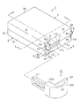
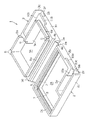
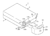
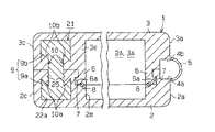
図1及び図2に示すように、携帯機を構成するケース本体1は略直方体状をなし、それぞれ一方が開口した箱状の第1ケース部2及び第2ケース部3が組み付けられることにより構成されている。
DESCRIPTION OF EMBODIMENTS Hereinafter, an embodiment embodying the present invention will be described in detail with reference to FIGS.
As shown in FIGS. 1 and 2, a case
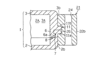
第1ケース部2及び第2ケース部3は略左右対称形状をなし、部品収容空間2A,3Aを有している。第1ケース部2における第1側壁2aの外面の上部には段差部4aが設けられ、第2ケース部3における第1側壁3aの外面の上部には段差部4bが設けられている。また、これら段差部4a,4bの側端はヒンジ部5によって連結されており、両ケース部2,3及びヒンジ部5は一体に形成されている。そして、各ケース部2,3は、ヒンジ部5を中心として回動され、それぞれ開口端同士を突き合わせた状態に組み付けられる。このため、ケース本体1は、部品収容空間2A,3Aを内部に有する箱体となる。
The
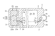
図2、図4及び図5に示すように、第2ケース部3の第1〜第4側壁3a〜3d及び隔壁3eの内面には、それぞれ開口端から突出する係止片6が形成されている。各係止片6の先端には、外方に突出する係止爪6aが形成されている。一方、第1ケース部2の第1〜第4側壁2a〜2d及び隔壁2eの内面には、各係止爪6aと係合する係合部7が設けられている。また、該第1〜第4側壁2a〜2d及び隔壁2eの内面において各係止片6の先端と対峙する箇所には、ゴム等の弾性部材からなるシール部材8が配設されている。このシール部材8は、該第1〜第4側壁2a〜2d及び隔壁2eの内面全体に亘って設けられている。このため、第1ケース部2と第2ケース部3との組付状態にあっては、図4及び図5に示すように、各係止片6の係止爪6aが係合部7に係合するとともに、該係止片6の先端縁がシール部材8を押圧した状態となる。すなわち、第1ケース部2と第2ケース部3とは、互いに係合することで組付状態となるスナップフィット構造となっている。
As shown in FIGS. 2, 4, and 5,
図1に示すように、各ケース部2,3の第1側壁2a,3aと隣り合う第2側壁2b,3bには、同第2側壁2b,3bに開口するメカキー収容部9が設けられている。このメカキー収容部9は、第1側壁2a,3aと対向する第3側壁2c,3cの近傍に設けられている。
As shown in FIG. 1, the
詳しくは、図2に示すように、メカキー収容部9は、第1ケース部2の第3側壁2cの近傍に設けられた第1メカキー収容部位9aと、第2ケース部3の第3側壁3cの近傍に設けられた第2メカキー収容部位9bとによって構成されている。第1メカキー収容部位9aは、第1ケース部2内に設けられた隔壁2eと第3側壁2cと底壁2fの一部とによって包囲された空間であり、該隔壁2eによって部品収容空間2Aと隔絶された状態となるように設けられている。また、第2メカキー収容部位9bは、第2ケース部3内に設けられた隔壁3eと第3側壁3cと底壁3fの一部とによって包囲された空間であり、該隔壁3eによって部品収容空間3Aと隔絶された状態となるように設けられている。
Specifically, as shown in FIG. 2, the mechanical
図1、図2及び図4に示すように、各ケース部2,3の隔壁2e,3eにおけるメカキー収容部9側の面には、第1突条片10a,10bが突設されている。これら第1突条片10a,10bは、隔壁2e,3e及びメカキー収容部9の開口縁に形成されている。また、各第1突条片10a,10bは、両隔壁2e,3eの開口端同士が一致した際に1つの構造物になるとともに、該一致した部位に対して対称形状となるように形成されている。そして、これら第1突条片10a,10bにより、突条からなる第1被挟持部10が構成されている。詳しくは、第1突条片10aにおいて第2ケース部3との合わせ面と対向する側の端縁10cは、メカキー収容部9の内部に向かうに従って第1ケース部2の底壁2fに近づくように形成されている。また、第1突条片10bにおいて第1ケース部2との合わせ面と対向する側の端縁10cは、メカキー収容部9の内部に向かうに従って第2ケース部3の底壁2fに近づくように形成されている。すなわち、各第1突条片10a,10bは、メカキー収容部9の内部方向に幅広となるように形成されている。よって、第1被挟持部10は、メカキー収容部9の内部方向に幅広となるテーパ状をなしている。また、図4に示すように、第1被挟持部10は、アリ状に形成されている。
As shown in FIGS. 1, 2, and 4, first protruding strips 10 a, 10 b are projected from the surfaces of the
図1、図2及び図5に示すように、各ケース部2,3の第2側壁2b,3bの外面には、第2突条片11a,11bが突設されている。これら第2突条片11a,11bは、一端が第1突条片10a,10bに連結され、他端が第2側壁2b,3bの中央付近に位置するように形成されている。また、各第2突条片11a,11bは、両第2側壁2b,3bの開口端同士が一致した際に1つの構造物になるとともに、該一致した部位に対して対称形状となる略直方体状に形成されている。そして、これら第2突条片11a,11bにより、突条からなる第2被挟持部11が構成されている。
As shown in FIGS. 1, 2, and 5,
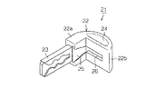
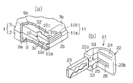
ところで、図1及び図4に示すように、このように構成されたケース本体1には、メカキー部21が装着される。図3にも併せ示すように、メカキー部21は、略L字状をなす把持部22と、該把持部22に固着された板状のキープレート23とを備えている。キープレート23には内溝のキーパターンが形成されている。把持部22は、一端にキープレート23が固着されたキー固着部22aと、該キー固着部22aの他端からほぼ90゜屈曲して延び、キーホルダーなどを挿通可能な貫通孔24を有する延設部22bとによって構成されている。
By the way, as shown in FIG.1 and FIG.4, the mechanical
また、把持部22の内角側の面には、前記ケース本体1の第1被挟持部10と一致する第1挟着部25、及び第2被挟持部11と一致する第2挟着部26が凹設されている。詳しくは、第1挟着部25は、第1被挟持部10に係合するアリ溝となっており、キー固着部22aに設けられている。一方、第2挟着部26は、第2被挟持部11に係合する溝部となっており、延設部22bに設けられている。これら第1挟着部25及び第2挟着部26は連通しており、全体として1つの溝部となっている。
Further, on the inner angle side surface of the gripping
このように構成されたケース本体1の部品収容空間2A,3Aには、通信手段としての通信モジュールが収容される。該通信モジュールは、車両や住宅のドアなどに配設された施錠装置を電気的に駆動制御する施解錠制御装置と通信可能に構成され、該通信によって施解錠制御装置を遠隔操作可能となっている。そして、ケース本体1、メカキー部21及び通信モジュールにより、施解錠制御装置を遠隔操作する携帯機が構成される。
Communication modules as communication means are accommodated in the
また、メカキー部21は、前記施錠装置を機械的に駆動して錠を施解錠するためのものであり、本実施形態では、エマージェンシーキーとして用いられるようになっている。
次に、このように構成されたケース本体1及びメカキー部21の組付手順について説明する。
The mechanical
Next, a procedure for assembling the case
まず、第1ケース部2と第2ケース部3との分離状態(図2参照)において、部品収容空間2Aに通信モジュールを収容する。そして、ヒンジ部5を支点として第2ケース部3を回動させ、各係止片6の係止爪6aを係合部7に係合させることにより、両ケース部2,3同士を組み付ける。これにより、両ケース部2,3の開口端同士が突き合わさった状態になるとともに、係止片6の先端によってシール部材8が弾性変形した状態となる(図4参照)。
First, in a state where the
続いて、メカキー収容部9内に、メカキー部21のキープレート23及びキー固着部22aを挿入する。そして、キー固着部22aを挿入する際には、同キー固着部22aの第1挟着部25をケース本体1の第1被挟持部10にスライド嵌合する(図4参照)とともに、延設部22bの第2挟着部26をケース本体1の第2被挟持部11に嵌め込む(図5参照)。これにより、各被挟持部10,11は、各挟着部25,26によって挟着された状態となる。このため、ケース本体1は、メカキー部21により、2辺挟持された状態となる。また、第1ケース部2及び第2ケース部3は、メカキー部21によって挟着保持された状態となり、分離不能となる。
Subsequently, the
したがって、本実施形態によれば以下のような効果を得ることができる。
(1)ケース本体1は、第1ケース部2及び第2ケース部3が互いに係合することに加え、両ケース部2,3に設けられた第1被挟持部10及び第2被挟持部11がメカキー部21の第1挟着部25及び第2挟着部26によって挟着されることにより、分離困難な組立完了状態となる。つまり、第1ケース部2及び第2ケース部3は、互いの係合力に加え、各挟着部25,26と各被挟持部10,11との挟着力によって強固に結合された状態となる。このため、両ケース部2,3同士の高い結合力を得ることができる。また、該結合にネジ締めなどの作業が不要であるため、両ケース部2,3同士を容易に結合・分離することができる。よって、ケース本体1内に収容される通信モジュールのメンテナンスも容易に行うことができる。
Therefore, according to the present embodiment, the following effects can be obtained.
(1) The
(2)各ケース部2,3の第1突条片10a,10b及び第2突条片11a,11bは、両ケース部2,3の開口端同士が一致しないと、第1被挟持部10及び第2被挟持部11として機能しない。すなわち、第1ケース部2の係止爪6aと第2ケース部3の係合部7とが完全に係合状態にならないと、各被挟持部10,11を各挟着部25,26によって挟着できないため、ケース本体1にメカキー部21を組み付けることができない。よって、ケース本体1にメカキー部21を組み付けることができるか否かにより、係止爪6aと係合部7とが完全に係合しているか否かを認識することができる。つまり、ケース本体1に対するメカキー部21の組み付け可否により、係止爪6aと係合部7との不完全な係合を確実に防止することができる。
(2) If the opening ends of the
(3)第1ケース部2と第2ケース部3との間には弾性体からなるシール部材8が介在されており、両ケース部2,3同士を組み付けた状態にあっては、係止片6の先端によってシール部材8を押圧した状態となる。このため、両ケース部2,3の結合箇所が、シール部材8を介して密着し、部品収容空間2A,3Aが確実に密閉された状態となる。よって、部品収容空間2A,3Aへの水等の侵入を確実に防止することができ、部品収容空間2A,3Aの高い防水性を確保することができる。
(3) A
しかも、両ケース部2,3はメカキー部21によって挟着されるため、係止爪6aと係合部7との係合箇所は、シール部材8からの反力を受けにくくなる。よって、該シール部材8からの反力に起因して係止片6及び係合部7にクリープ変形等が生じるのを抑止することができ、両ケース部2,3の結合力の低下を抑止することができる。
In addition, since the
(4)第1ケース部2及び第2ケース部3は、隣り合う二辺がメカキー部21によって挟着される。このため、メカキー部21とケース本体1とがいっそう分離しにくくなる。それゆえ、第1ケース部2と第2ケース部3との結合状態もより強固に保持される。よって、両ケース部2,3同士の結合力をさらに高めることができる。
(4) The
(5)ヒンジ部5によって第1ケース部2と第2ケース部3とが連結されるため、両ケース部2,3を組み付けていない状態においても両者が分離しない。また、被挟持部は両ケース部2,3においてヒンジ部5が設けられた側壁と対向する側に設けられているため、該被挟持部を挟着部によって挟着することにより、両ケース部2,3をよりいっそう強固に結合することができる。
(5) Since the
(6)第1被挟持部10はテーパ形状をなしているため、メカキー部21の第1挟着部25をケース本体1の第1被挟持部10にスライド嵌合させやすくすることができる。つまり、ケース本体1に対するメカキー部21の組付性を向上させることができる。
(6) Since the first sandwiched
(7)ケース本体1の第1被挟持部10及びメカキー部21の第1挟着部25は、アリ構造となっているため、ケース本体1とメカキー部21とをいっそう強固に結合することができ、メカキー部21の意図しないケース本体1からの分離を確実に防止することができる。
(7) Since the first sandwiched
なお、本発明の実施形態は以下のように変更してもよい。
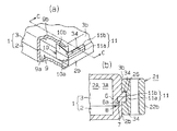
・ 前記実施形態では、ケース本体1にメカキー部21を装着することで携帯機が構成されるようになっている。しかし、例えば図6に示すように、キープレート23を備えておらず、キーホルダーなどのアクセサリ部品を装着可能な貫通孔24を有する把持部22からなるアクセサリ部材31を、ケース本体1に装着することで携帯機が構成されるようになっていてもよい。このようにしても、ケース本体1は、第1ケース部2及び第2ケース部3が互いに係合することに加え、両ケース部2,3にそれぞれ設けられた各被挟持部10,11がアクセサリ部材31の各挟着部25,26によって挟着されることにより、強固に結合された状態となる。このため、両ケース部2,3同士の高い結合力を得ることができる。つまり、携帯機は、必ずしもメカキー部21を備えている必要はない。
In addition, you may change embodiment of this invention as follows.
In the embodiment, the portable device is configured by attaching the mechanical
・ 図7(a)に示すように第1被挟持部10を構成する各第1突条片10a,10bの端縁10cにそれぞれ突部32を形成するとともに、図7(b)に示すようにメカキー部21の第1挟着部25に該突部32と係合可能な凹部33を設けてもよい。すなわち、第1被挟持部10及び第1挟着部25に、互いに係合する係合構造を設けてもよい。このようにすれば、メカキー部21をケース本体1に装着した際に、第1被挟持部10の突部32と第1挟着部25の凹部33とが係合し、ケース本体1からメカキー部21が分離しにくくなる。このため、メカキー部21とケース本体1との意図しない分離が抑止され、第1ケース部2と第2ケース部3との結合状態もより強固に保持される。
As shown in FIG. 7 (a), as shown in FIG. 7 (b), the
・ 図8(a),(b)に示すように第2被挟持部11を構成する各第2突条片11a,11bの外側面にそれぞれ突部34を形成するとともに、メカキー部21の第2挟着部26を該突部34と係合可能に設けてもよい。すなわち、第2被挟持部11及び第2挟着部26に、互いに係合する係合構造を設けてもよい。このようにすれば、メカキー部21をケース本体1に装着した際に、第2被挟持部11の突部34と第2挟着部26とが係合し、ケース本体1からメカキー部21が分離しにくくなる。このため、メカキー部21とケース本体1との意図しない分離が抑止され、第1ケース部2と第2ケース部3との結合状態もより強固に保持される。
As shown in FIGS. 8A and 8B, the
・ 図9に示すように、第1ケース部2及び第2ケース部3の第3側壁2c,3cにおける各メカキー収容部位9a,9b側の側面にも第1突条片10a,10bを形成してもよい。それとともに、メカキー部21のキー固着部22aにおいて第1挟着部25が設けられた面と逆側の面にも第1挟着部25を設けてもよい。このようにすれば、第1被挟持部10及び第1挟着部25が2箇所に設けられた状態となるため、ケース本体1にメカキー部21を装着することにより、各ケース部2,3をさらに強固に結合させることができる。
As shown in FIG. 9, the
・ 前記実施形態においてケース本体1は、隣り合う二辺がメカキー部21によって挟着されるようになっている。しかし、例えば第2被挟持部11を省略して、ケース本体1の一辺のみがメカキー部21によって挟着されるように変更してもよい。
In the embodiment, the
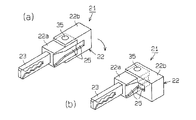
また、こうした変更態様にあっては、例えば図10(a),(b)に示すように、メカキー部21の把持部22の形状を変更してもよい。詳しくは、把持部22のキー固着部22aと延設部22bとを別体に構成し、キー固着部22aと延設部22bとを相対的に回動可能に支持する回動支持部35によって両者を連結する。そして、キー固着部22a及び延設部22bに第1挟着部25を設け、該第1挟着部25によってケース本体1の第1被挟持部10を挟着するようにする。このようにすれば、メカキー部21の大部分をケース本体1のメカキー収容部9内に収容することができるため、携帯機の小型化を図ることができる。また、メカキー部21の使用時においては、図10(b)に示すように、延設部22bをキー固着部22aに対して90゜回動させることにより、把持しやすい形状にすることができる。
In such a change mode, for example, as shown in FIGS. 10A and 10B, the shape of the
・ 前記実施形態においてケース本体1は、隣り合う二辺がメカキー部21によって挟着されるようになっている。しかし、例えば各ケース部2,3の第1側壁2a,3aにも、第1被挟持部10や第2被挟持部11と同様の第3被挟持部を設ける。それとともに、第1側壁2a,3aを覆う形状となるようにメカキー部21の把持部22の形状を変更し、該変更箇所に、該第3被挟持部を挟着可能な第3挟着部を設けてもよい。このようにすれば、ケース本体1は、三辺がメカキー部21によって挟着されるようになるため、両ケース部2,3をより一層強固に結合することができる。なお、この場合、各ケース部2,3においてメカキー部21によって挟着されていない側壁(第4側壁2d,3d)にヒンジ部5が設けられるとなおよい。
In the embodiment, the
・ 前記実施形態では、第1ケース部2と第2ケース部3とがヒンジ部5によって連結されている。しかし、各ケース部2,3は、必ずしもヒンジ部5によって連結されている必要はなく、個別に形成されていてもよい。
In the embodiment, the
・ 前記実施形態において第1被挟持部10は、テーパ形状をなしている。しかし、第1被挟持部10は、図7(a)に示したように、必ずしもテーパ形状をなしている必要はない。
-In the said embodiment, the
・ 第1被挟持部10及び第1挟着部25は、必ずしもアリ構造をなしている必要はない。
・ 前記実施形態では、第1ケース部2には隔壁2eが設けられ、第2ケース部3には隔壁3eが設けられている。そして、これら隔壁2e,3eが設けられることにより、ケース本体1にメカキー収容部9が設けられた状態となっている。しかし、これら隔壁2e,3e及びメカキー収容部9を省略するとともに、各ケース部2,3の第3側壁2c,3cに第1被挟持部10を設けてもよい。
The first sandwiched
In the embodiment, the
次に、特許請求の範囲に記載された技術的思想のほかに、前述した実施形態によって把握される技術的思想を以下に列挙する。
(1) 請求項3に記載の携帯機のケース構造において、前記第1ケース部及び前記第2ケース部の二辺に設けられた被挟持部のうち、一辺側には前記挟着部がスライド嵌合され、他辺側には前記挟着部が嵌め込まれ、該嵌め込まれる側の被挟持部と、該挟着部においてその被挟持部と対応する箇所とに、互いに係合して挟着状態を保持する挟着保持構造を設けたこと。
Next, in addition to the technical ideas described in the claims, the technical ideas grasped by the embodiment described above are listed below.
(1) In the case structure of the portable device according to
(2) 請求項1〜5、技術的思想(1)のいずれか1項に記載の携帯機のケース構造において、前記被挟持部の少なくとも一部をアリ形状とし、前記挟着部において前記アリ状部位と対応する箇所をアリ溝としたこと。
(2) In the case structure of the portable device according to any one of
上記技術的思想(1),(2)に記載の発明によれば、ケース本体とメカキー部またはアクセサリ部材とをより強固に組み付けることができる。
(3) 請求項1〜5、技術的思想(1),(2)のいずれか1項に記載の携帯機のケース構造において、前記第1ケース部と前記第2ケース部との間に弾性体からなるシール材を介在したこと。この技術的思想(3)に記載の発明によれば、高い防水性を確保することができるとともに、第1ケース部と第2ケース部にクリープ変形が生じるのを抑止することができる。
According to the inventions described in the technical ideas (1) and (2), the case main body and the mechanical key portion or the accessory member can be assembled more firmly.
(3) In the case structure of the portable device according to any one of
1…ケース本体、2…第1ケース部、3…第2ケース部、5…ヒンジ部、10…第1被挟持部、10a,10b…第1突条片、11…第2被挟持部、11a,11b…第2突条片、21…メカキー部、25…第1挟着部、26…第2挟着部、31…アクセサリ部材。
DESCRIPTION OF
Claims (5)
開口端同士を突き合わせた状態で互いに係合するスナップフィット構造を有する箱状の第1ケース部及び第2ケース部によって構成され、内部に前記施解錠制御装置との通信を行う通信手段が収容されるケース本体と、
前記施錠装置を機械的に操作可能なメカキー部とを備え、
前記第1ケース部及び前記第2ケース部の外側面における開口縁付近にそれぞれ被挟持部を設けるとともに、前記メカキー部に、該被挟持部を挟着する挟着部を設けたことを特徴とする携帯機のケース構造。 It is configured to be communicable with a locking / unlocking control device that electrically drives and controls the locking device, and is a case structure of a portable machine that remotely operates the locking / unlocking control device through the communication,
Composed of a box-shaped first case part and a second case part having a snap-fit structure that engage with each other in a state where the open ends are butted together, and communication means for communicating with the locking / unlocking control device is accommodated therein. A case body,
A mechanical key unit capable of mechanically operating the locking device;
A sandwiched portion is provided in the vicinity of an opening edge on the outer surface of each of the first case portion and the second case portion, and a sandwiching portion for sandwiching the sandwiched portion is provided in the mechanical key portion. The case structure of a portable device.
開口端同士を突き合わせた状態で互いに係合するスナップフィット構造を有する箱状の第1ケース部及び第2ケース部によって構成され、内部に前記施解錠制御装置との通信を行う通信手段が収容されるケース本体と、
前記ケース本体に着脱可能なアクセサリ部材とを備え、
前記第1ケース部及び前記第2ケース部の外側面における開口縁付近にそれぞれ被挟持部を設けるとともに、前記アクセサリ部材に、該被挟持部を挟着する挟着部を設けたことを特徴とする携帯機のケース構造。 It is configured to be communicable with a locking / unlocking control device that electrically drives and controls the locking device, and is a case structure of a portable machine that remotely operates the locking / unlocking control device through the communication,
Composed of a box-shaped first case part and a second case part having a snap-fit structure that engage with each other in a state where the open ends are butted together, and communication means for communicating with the locking / unlocking control device is accommodated therein. A case body,
An accessory member removable from the case body,
A sandwiched portion is provided in the vicinity of an opening edge on the outer surface of each of the first case portion and the second case portion, and a sandwiching portion for sandwiching the sandwiched portion is provided on the accessory member. The case structure of a portable device.
Priority Applications (4)
| Application Number | Priority Date | Filing Date | Title |
|---|---|---|---|
| JP2004110193A JP2005290905A (en) | 2004-04-02 | 2004-04-02 | Portable machine case structure |
| US11/096,243 US7310980B2 (en) | 2004-04-02 | 2005-03-31 | Case for remote control key |
| DE200510015085 DE102005015085A1 (en) | 2004-04-02 | 2005-04-01 | Housing for a remote control key |
| US11/958,166 US7513134B2 (en) | 2004-04-02 | 2007-12-17 | Case for remote control key |
Applications Claiming Priority (1)
| Application Number | Priority Date | Filing Date | Title |
|---|---|---|---|
| JP2004110193A JP2005290905A (en) | 2004-04-02 | 2004-04-02 | Portable machine case structure |
Publications (1)
| Publication Number | Publication Date |
|---|---|
| JP2005290905A true JP2005290905A (en) | 2005-10-20 |
Family
ID=35059150
Family Applications (1)
| Application Number | Title | Priority Date | Filing Date |
|---|---|---|---|
| JP2004110193A Pending JP2005290905A (en) | 2004-04-02 | 2004-04-02 | Portable machine case structure |
Country Status (3)
| Country | Link |
|---|---|
| US (2) | US7310980B2 (en) |
| JP (1) | JP2005290905A (en) |
| DE (1) | DE102005015085A1 (en) |
Cited By (11)
| Publication number | Priority date | Publication date | Assignee | Title |
|---|---|---|---|---|
| JP2007231605A (en) * | 2006-02-28 | 2007-09-13 | Alpha Corp | Unlock key device |
| JP2007231604A (en) * | 2006-02-28 | 2007-09-13 | Alpha Corp | Electronic key device |
| JP2007231602A (en) * | 2006-02-28 | 2007-09-13 | Alpha Corp | Electronic key device |
| JP2009121123A (en) * | 2007-11-14 | 2009-06-04 | Tokai Rika Co Ltd | Portable machine |
| JPWO2008068861A1 (en) * | 2006-12-06 | 2010-03-18 | 株式会社 立沢化成 | Storage case lock structure |
| US7698920B2 (en) | 2006-03-14 | 2010-04-20 | Kabushiki Kaisha Tokai-Rika-Denki-Seisakusho | Mechanical key and locking/unlocking key |
| JP2012112118A (en) * | 2010-11-22 | 2012-06-14 | Tokai Rika Co Ltd | Mechanical key unit |
| JP2015067999A (en) * | 2013-09-27 | 2015-04-13 | Ykk Ap株式会社 | Lock device |
| JP2016079654A (en) * | 2014-10-16 | 2016-05-16 | 三菱電機株式会社 | Electronic key device |
| JP2020063663A (en) * | 2020-01-28 | 2020-04-23 | 株式会社WEST inx | Latch lock |
| CN113728364A (en) * | 2019-04-29 | 2021-11-30 | 海拉有限双合股份公司 | Electronic key system for a motor vehicle |
Families Citing this family (24)
| Publication number | Priority date | Publication date | Assignee | Title |
|---|---|---|---|---|
| DE10322853A1 (en) * | 2003-05-21 | 2004-12-16 | Volkswagen Ag | Key system for a motor vehicle |
| DE10357931B4 (en) * | 2003-12-11 | 2006-09-07 | Daimlerchrysler Ag | Electronic key |
| FR2868801B1 (en) * | 2004-04-08 | 2006-07-14 | Valeo Securite Habitacle Sas | RETRACTABLE ROD KEY HAVING ROD DRIVING MEANS TO A DEPLOYED POSITION |
| DE602005024629D1 (en) * | 2004-09-10 | 2010-12-16 | Hy Ko Products Co | HIGH FREQUENCY IDENTIFICATION SYSTEM (RFID) FOR THE MANUFACTURE, DISTRIBUTION AND RETAIL OF KEYS |
| US9963908B2 (en) | 2004-09-10 | 2018-05-08 | Hy-Ko Products Company | Data key and method of using same |
| JP4510698B2 (en) * | 2005-05-19 | 2010-07-28 | 株式会社東海理化電機製作所 | Mechanical key |
| JP4658764B2 (en) * | 2005-10-05 | 2011-03-23 | 株式会社東海理化電機製作所 | Cylinder lock, key, and portable device |
| DE102006023143A1 (en) * | 2006-05-16 | 2007-11-22 | Huf Hülsbeck & Fürst Gmbh & Co. Kg | Electronic key |
| AT505781A1 (en) * | 2007-09-27 | 2009-04-15 | Victorinox Ag | PLATFORM RECORDING USE, ESPECIALLY TOOL CARD |
| WO2010109806A1 (en) * | 2009-03-26 | 2010-09-30 | パナソニック株式会社 | Electronic lock |
| US20110019342A1 (en) * | 2009-07-27 | 2011-01-27 | Justin Moore | Remote control |
| USD613256S1 (en) | 2009-07-27 | 2010-04-06 | Justin Moore | Remote control |
| DE102010061457A1 (en) * | 2010-12-21 | 2012-06-21 | Huf Hülsbeck & Fürst Gmbh & Co. Kg | Electronic key |
| FR2973918B1 (en) * | 2011-04-08 | 2013-04-26 | Schneider Electric Ind Sas | DEVICE FOR REMOTELY CONTROLLING AN ELECTRICAL APPARATUS AND METHOD FOR STARTING THE DEVICE |
| DE102011052079A1 (en) | 2011-07-22 | 2013-01-24 | Huf Hülsbeck & Fürst Gmbh & Co. Kg | Electronic key for a security system with a mechanism for releasing a battery compartment cover |
| JP5557829B2 (en) * | 2011-12-07 | 2014-07-23 | オムロンオートモーティブエレクトロニクス株式会社 | Vehicle portable device |
| USD695590S1 (en) * | 2012-03-23 | 2013-12-17 | Stanley Works (Europe) Gmbh | Key support |
| US9593514B2 (en) * | 2013-02-18 | 2017-03-14 | Ford Global Technologies, Llc | Seamless exterior handle for a vehicle door |
| FR3008124A1 (en) * | 2013-07-02 | 2015-01-09 | Johnson Contr Automotive Elect | MECHANICAL MODULE AND KEY |
| FI126753B (en) * | 2014-06-27 | 2017-05-15 | Abloy Oy | Padlock |
| USD773406S1 (en) * | 2015-02-03 | 2016-12-06 | Lg Electronics Inc. | Smart key for automobiles |
| KR200483223Y1 (en) * | 2015-10-15 | 2017-04-17 | 주식회사 서연전자 | Fob key of Vehicles |
| CN110278670B (en) * | 2018-03-14 | 2020-09-04 | 上海海拉电子有限公司 | Locking device and shell with same |
| CN114517609A (en) * | 2022-04-21 | 2022-05-20 | 毕晓文 | Intelligent automobile key device capable of being installed in lossless mode, lossless installation method and vehicle control method |
Family Cites Families (16)
| Publication number | Priority date | Publication date | Assignee | Title |
|---|---|---|---|---|
| IT1260819B (en) * | 1992-05-13 | 1996-04-22 | Silca Spa | KEY COMBINATION AND RELATED CASE |
| US5388691A (en) * | 1993-10-21 | 1995-02-14 | White; Nona J. | Protective case for remote control transmitter |
| JP3298736B2 (en) * | 1994-04-28 | 2002-07-08 | 本田技研工業株式会社 | Portable electronic equipment for vehicles |
| US7257971B2 (en) * | 2000-07-31 | 2007-08-21 | Autronics Plastics Inc. | Case with internal lock |
| US20040182119A1 (en) * | 2003-03-21 | 2004-09-23 | Michael Lax | Systems and methods for containing and locking assets |
| JP2002322841A (en) | 2001-04-24 | 2002-11-08 | Tokai Rika Co Ltd | Electronic key |
| JP2003113683A (en) | 2001-10-03 | 2003-04-18 | Alps Electric Co Ltd | Mechanical key mounting structure of remote control device |
| US6601414B1 (en) * | 2002-01-17 | 2003-08-05 | Kun-Fa Chang | Anti-theft compact disk casings |
| FR2851783B1 (en) * | 2003-02-28 | 2005-04-08 | Valeo Securite Habitacle Sas | KEY HOUSING |
| US6880372B2 (en) * | 2003-03-10 | 2005-04-19 | Kim Jae-Tae | Security device for information storage media |
| JP2004353404A (en) * | 2003-05-30 | 2004-12-16 | Denso Corp | Portable electronic key system |
| ITBO20040005U1 (en) * | 2004-01-26 | 2004-04-26 | Gt Line S R L | LOCK LOCK FOR SUITCASES, TRUNKS AND SIMILAR |
| JP4643152B2 (en) * | 2004-01-30 | 2011-03-02 | 株式会社デンソー | Electronic key system portable machine |
| US20060081020A1 (en) * | 2004-10-20 | 2006-04-20 | Yu-Ling Hsiao | Anti-theft apparatus and anti-theft subject for rental or the like |
| JP4510698B2 (en) * | 2005-05-19 | 2010-07-28 | 株式会社東海理化電機製作所 | Mechanical key |
| JP4695463B2 (en) * | 2005-09-01 | 2011-06-08 | 株式会社東海理化電機製作所 | Portable machine |
-
2004
- 2004-04-02 JP JP2004110193A patent/JP2005290905A/en active Pending
-
2005
- 2005-03-31 US US11/096,243 patent/US7310980B2/en not_active Expired - Fee Related
- 2005-04-01 DE DE200510015085 patent/DE102005015085A1/en not_active Withdrawn
-
2007
- 2007-12-17 US US11/958,166 patent/US7513134B2/en not_active Expired - Fee Related
Cited By (13)
| Publication number | Priority date | Publication date | Assignee | Title |
|---|---|---|---|---|
| JP2007231604A (en) * | 2006-02-28 | 2007-09-13 | Alpha Corp | Electronic key device |
| JP2007231602A (en) * | 2006-02-28 | 2007-09-13 | Alpha Corp | Electronic key device |
| JP2007231605A (en) * | 2006-02-28 | 2007-09-13 | Alpha Corp | Unlock key device |
| US8001817B2 (en) | 2006-03-14 | 2011-08-23 | Kabushiki Kaisha Tokai-Rika-Denki-Seisakusho | Mechanical key and locking/unlocking key |
| US7698920B2 (en) | 2006-03-14 | 2010-04-20 | Kabushiki Kaisha Tokai-Rika-Denki-Seisakusho | Mechanical key and locking/unlocking key |
| JPWO2008068861A1 (en) * | 2006-12-06 | 2010-03-18 | 株式会社 立沢化成 | Storage case lock structure |
| JP2009121123A (en) * | 2007-11-14 | 2009-06-04 | Tokai Rika Co Ltd | Portable machine |
| JP2012112118A (en) * | 2010-11-22 | 2012-06-14 | Tokai Rika Co Ltd | Mechanical key unit |
| JP2015067999A (en) * | 2013-09-27 | 2015-04-13 | Ykk Ap株式会社 | Lock device |
| JP2016079654A (en) * | 2014-10-16 | 2016-05-16 | 三菱電機株式会社 | Electronic key device |
| CN113728364A (en) * | 2019-04-29 | 2021-11-30 | 海拉有限双合股份公司 | Electronic key system for a motor vehicle |
| CN113728364B (en) * | 2019-04-29 | 2023-11-28 | 海拉有限双合股份公司 | Electronic key system for motor vehicles |
| JP2020063663A (en) * | 2020-01-28 | 2020-04-23 | 株式会社WEST inx | Latch lock |
Also Published As
| Publication number | Publication date |
|---|---|
| US20080105015A1 (en) | 2008-05-08 |
| US20050223766A1 (en) | 2005-10-13 |
| US7513134B2 (en) | 2009-04-07 |
| US7310980B2 (en) | 2007-12-25 |
| DE102005015085A1 (en) | 2005-11-24 |
Similar Documents
| Publication | Publication Date | Title |
|---|---|---|
| JP2005290905A (en) | Portable machine case structure | |
| JP4301303B2 (en) | Electronic key system portable machine | |
| JP6091968B2 (en) | Battery pack for electric tools | |
| JPH098474A (en) | Case seal structure and assembly method thereof | |
| EP4006273B1 (en) | Door latch device | |
| CN103459738B (en) | Electron key | |
| US9723739B2 (en) | Electronic control unit and protective case | |
| JP3960804B2 (en) | Waterproof structure of keyless entry portable device | |
| JP2014203702A (en) | Power tool battery pack | |
| JP4911089B2 (en) | Packing, waterproof structure using the packing, and electronic device provided with the waterproof structure using the packing | |
| EP3992402B1 (en) | Door latch device | |
| JP2004068417A (en) | Portable device of keyless entry device and method of manufacturing the same | |
| JP4652950B2 (en) | Detachable vehicle antenna | |
| JP2002070373A (en) | Transmitter | |
| JP2021168264A5 (en) | ||
| US20090151973A1 (en) | Mobile device | |
| US20190270430A1 (en) | Electronic key | |
| JP4917324B2 (en) | Battery contact terminal holding structure and electronic key battery contact terminal holding structure | |
| JP2005240380A (en) | Portable machine | |
| KR102855133B1 (en) | Smartkey for vehicle | |
| JP2001200664A (en) | Portable unit for keyless entry device | |
| JP7448121B2 (en) | smart key device | |
| JP2004165496A (en) | Electronic equipment storage case | |
| JPS6347091Y2 (en) | ||
| JP2012146595A (en) | Electric device |
Legal Events
| Date | Code | Title | Description |
|---|---|---|---|
| A621 | Written request for application examination |
Free format text: JAPANESE INTERMEDIATE CODE: A621 Effective date: 20061020 |
|
| A977 | Report on retrieval |
Free format text: JAPANESE INTERMEDIATE CODE: A971007 Effective date: 20091015 |
|
| A131 | Notification of reasons for refusal |
Free format text: JAPANESE INTERMEDIATE CODE: A131 Effective date: 20091027 |
|
| A02 | Decision of refusal |
Free format text: JAPANESE INTERMEDIATE CODE: A02 Effective date: 20100309 |