JP2005290901A - Keyless entry system - Google Patents
Keyless entry system Download PDFInfo
- Publication number
- JP2005290901A JP2005290901A JP2004109836A JP2004109836A JP2005290901A JP 2005290901 A JP2005290901 A JP 2005290901A JP 2004109836 A JP2004109836 A JP 2004109836A JP 2004109836 A JP2004109836 A JP 2004109836A JP 2005290901 A JP2005290901 A JP 2005290901A
- Authority
- JP
- Japan
- Prior art keywords
- key
- entry system
- keyless entry
- battery
- door
- Prior art date
- Legal status (The legal status is an assumption and is not a legal conclusion. Google has not performed a legal analysis and makes no representation as to the accuracy of the status listed.)
- Pending
Links
- 230000036760 body temperature Effects 0.000 claims abstract description 16
- 230000006854 communication Effects 0.000 claims description 9
- 238000004891 communication Methods 0.000 claims description 9
- 230000010356 wave oscillation Effects 0.000 abstract description 9
- 230000001939 inductive effect Effects 0.000 abstract description 6
- 230000005540 biological transmission Effects 0.000 description 18
- 239000004065 semiconductor Substances 0.000 description 9
- 238000010586 diagram Methods 0.000 description 5
- 230000005678 Seebeck effect Effects 0.000 description 4
- 230000017525 heat dissipation Effects 0.000 description 4
- 230000006698 induction Effects 0.000 description 3
- 238000010248 power generation Methods 0.000 description 3
- 125000002066 L-histidyl group Chemical group [H]N1C([H])=NC(C([H])([H])[C@](C(=O)[*])([H])N([H])[H])=C1[H] 0.000 description 2
- 230000007423 decrease Effects 0.000 description 2
- 150000002500 ions Chemical class 0.000 description 2
- 230000010355 oscillation Effects 0.000 description 2
- 238000013459 approach Methods 0.000 description 1
- 230000007175 bidirectional communication Effects 0.000 description 1
- 238000005516 engineering process Methods 0.000 description 1
- 230000004907 flux Effects 0.000 description 1
- 229910052751 metal Inorganic materials 0.000 description 1
- 239000002184 metal Substances 0.000 description 1
- 150000002739 metals Chemical class 0.000 description 1
- 230000005855 radiation Effects 0.000 description 1
- 230000001960 triggered effect Effects 0.000 description 1
Images
Landscapes
- Lock And Its Accessories (AREA)
Abstract
【課題】キーの電池切れに対して、電池またはメカニカルキーを携帯しなくても、効率よくドアの解錠を行う。
【解決手段】キーレスエントリシステムに使用されるキー43の電源として熱電素子41を利用する。この熱電素子41に体温を伝達するだけで、熱電素子41が発電し、無線回路45に電力を供給することができる。誘導給電を利用せずに効率よくドアの解錠を行うことができるので、電磁波発振装置を搭載するためのスペースが必要なく、しかも、電磁波発振装置を稼動させるための多大な電力を必要としないので便利である。
【選択図】図1
An object of the present invention is to efficiently unlock a door without carrying a battery or a mechanical key when the battery of a key is dead.
A thermoelectric element is used as a power source for a key used in a keyless entry system. By simply transmitting the body temperature to the thermoelectric element 41, the thermoelectric element 41 can generate power and supply power to the radio circuit 45. Since the door can be efficiently unlocked without using inductive power feeding, there is no need for a space for mounting the electromagnetic wave oscillation device, and no great power is required to operate the electromagnetic wave oscillation device. So convenient.
[Selection] Figure 1
Description
本発明は、キーレスエントリシステム及びそれに関連する技術に関するものである。 The present invention relates to a keyless entry system and related technology.
従来の自動車においては、メカニカルキーをドアのキースロットに挿入してドアを解錠することが行われてきたが、最近では、携帯用送信機よりリモートコントロール信号を出力して車載用受信機によりこれを受信し、アクチュエータを駆動してドアのロック機構を制御するキーレスエントリシステムが搭載されつつある。 In a conventional automobile, a mechanical key is inserted into a key slot of a door to unlock the door, but recently, a remote control signal is output from a portable transmitter and an in-vehicle receiver is used. A keyless entry system that receives this and drives the actuator to control the door locking mechanism is being installed.
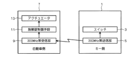
このキーリスエントリシステムとしては、例えば図3に示したものがある(従来技術1)。この従来技術1では、キー1側のスイッチ3を押すことにより、このスイッチ3からのトリガ信号が300MHz帯送信部5に入力され、この300MHz帯送信部5から自動車7側の300MHz帯受信部9に対して、キー1側内に予め記憶しておいたIDの情報を含めた暗号化された無線信号が送信される。そして、自動車7側においては、300MHz帯受信部9が無線信号を受信した時点で、その中に含まれるIDの情報を、マイコン等を有する施解錠制御手段11に伝送する。施解錠制御手段11は、IDの認証を行った後、アクチュエータ13のドアの解錠(アンロック)の駆動制御を行う。
An example of this key list entry system is shown in FIG. 3 (Prior Art 1). In this prior art 1, when a switch 3 on the key 1 side is pressed, a trigger signal from the switch 3 is input to the 300 MHz
かかる従来技術1は、キー1側から自動車7側への片方向通信により、無線でドアの解錠を行うものである。
In the related art 1, the door is unlocked wirelessly by one-way communication from the key 1 side to the
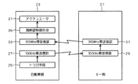
これとは別のキーリスエントリシステムの例(従来技術2)を図4に示す。この従来技術2は、運転者等がキー21を携帯した状態で、ドアノブに設置された感熱センサ等のタッチセンサを触ったり、ドアノブの近傍に配置された押し釦式スイッチを押したり、あるいはキー21が自動車23側を中心とする一定範囲内に近づくだけで、自動車23側がその旨を判断して自動的にドアの解錠(アンロック)を行うもので、自動車23側に設置されたトリガ手段25からのトリガ信号が100kHz帯送信部27に入力されると、この100kHz帯送信部27から100kHz帯の信号がキー21側に内蔵された100kHz帯受信部29に無線送信され、これを契機として、キー21側に内蔵された300MHz帯送信部31から自動車23側の300MHz帯受信部33に対して、キー21側内に予め記憶しておいたIDの情報を含めた無線信号が送信される。そして、自動車23側においては、300MHz帯受信部33が無線信号を受信した時点で、その中に含まれるIDの情報を、マイコン等を有する施解錠制御手段35に伝送する。施解錠制御手段35は、IDの認証を行った後、アクチュエータ37のドアの解錠(アンロック)の駆動制御を行う。
FIG. 4 shows another example of the key list entry system (prior art 2). In this prior art 2, with the driver carrying the
かかる従来技術2は、自動車23側とキー21側との双方向通信により、無線でドアの解錠を行うものである。
In the related art 2, the door is unlocked wirelessly by bidirectional communication between the
図3及び図4にそれぞれ示した両従来技術とも、キー1,21側の内部に電池が必要とされるが、このキー1,21側の電池が切れた場合は、その電池を取り替えるか、あるいはメカニカルキーをドアのキースロットに挿入してドアを解錠する必要があった。
Both of the prior arts shown in FIGS. 3 and 4 require batteries inside the
この場合、キー1,21側の電池切れに対応するために、運転者等は常に電池またはメカニカルキーを携帯していなければならず、いずれも運転者に負担を強いることとなっていた。
In this case, in order to cope with the battery exhaustion on the
そこで、例えば自動車側からキーに対して誘導給電を行うことも考えられる。この誘導給電は、主に250KHz以下または13.56MHz帯の長・中波帯の電磁波を利用して、IDタグやリーダライタのアンテナとしてコイルを用い、二つのコイルの誘導磁束による誘起電圧を利用することで交信する。この誘導給電を利用すれば、キー1,21側の電池が切れた場合に、自動車7,23側からキー1,21側に電磁波エネルギーを与え、この電磁波エネルギーによる誘起電圧によりキー1,21側から自動車7,23側に信号を無線送信できるため、キー1,21側の電池切れにも対応することが可能である。
Thus, for example, it is conceivable to perform induction power supply from the automobile side to the key. This induction power supply mainly uses electromagnetic waves in the long / medium wave band of 250 KHz or less or 13.56 MHz band, using coils as antennas for ID tags and reader / writers, and using the induced voltage due to the induced magnetic flux of the two coils. To communicate. By using this inductive power supply, when the batteries on the
しかしながら、かかる誘導給電を利用する場合は、自動車7,23側に電磁波を発信するための大がかりな電磁波発振装置を必要とするため、そのためのコストが増大するだけでなく、電磁波発振装置を搭載するためのスペースが必要となる。しかも、電磁波発振装置を稼動させるためには多大な電力が必要となることから、自動車7,23側での省電力化に逆行するという欠点がある。
However, when such inductive power feeding is used, a large-scale electromagnetic oscillation device for transmitting electromagnetic waves to the
そこで、本発明の課題は、キーの電池切れに対して、電池またはメカニカルキーを携帯しなくても、誘導給電を利用せずに効率よくドアの解錠を行うことができるキーレスエントリシステムを提供することにある。 Accordingly, an object of the present invention is to provide a keyless entry system that can efficiently unlock a door without using an induction power supply without carrying a battery or a mechanical key when the battery of the key is dead. There is to do.
上記課題を解決すべく、請求項1に記載の発明は、使用者が携帯する携帯器からの無線信号により自動車のドアの解錠を行うキーレスエントリシステムであって、前記携帯器と、自動車内に設置され、前記携帯器からの無線信号を受信してドアの解錠を制御する施解錠制御手段とを備え、前記携帯器は、前記自動車に対して通信するための無線回路と、少なくとも体温により電力を発電して前記無線回路に給電する熱電素子とを備えるものである。 In order to solve the above-mentioned problem, the invention described in claim 1 is a keyless entry system for unlocking a door of a vehicle by a wireless signal from a portable device carried by a user, the portable device and the interior of the vehicle. And a locking / unlocking control unit that receives a radio signal from the portable device and controls unlocking of the door, and the portable device includes a wireless circuit for communicating with the automobile, and at least a body temperature. And a thermoelectric element that generates electric power and supplies power to the wireless circuit.
請求項2に記載の発明は、請求項1に記載のキーレスエントリシステムであって、携帯器は、前記無線回路の前記自動車に対する通信を操作するためのスイッチをさらに備え、前記熱電素子は、前記スイッチ自体の構成部品として、または前記スイッチの近傍に設置されるものである。 The invention described in claim 2 is the keyless entry system according to claim 1, wherein the portable device further includes a switch for operating communication of the wireless circuit to the vehicle, and the thermoelectric element includes the It is installed as a component of the switch itself or in the vicinity of the switch.
請求項3に記載の発明は、請求項1に記載のキーレスエントリシステムであって、前記携帯器は電池を備え、前記携帯器の前記無線回路は、前記自動車からの無線信号を受信し、且つこの受信に応じて前記自動車に対する無線信号を送信し、前記熱電素子は、前記電池と並列して前記無線回路に電圧を印加するものである。 A third aspect of the present invention is the keyless entry system according to the first aspect, wherein the portable device includes a battery, the wireless circuit of the portable device receives a wireless signal from the automobile, and In response to this reception, a radio signal is transmitted to the automobile, and the thermoelectric element applies a voltage to the radio circuit in parallel with the battery.
請求項1〜請求項3に記載の発明のキーレスエントリシステムは、ユーザーが所持する携帯器の電池切れを心配することなく、体温を熱電素子に伝達するだけで、携帯器から自動車側に対する無線送信を行ってドアの解錠を行うことができるので、もしものときのキーの電池切れやメカニカルキーがない場合の安心感を得ることができる。特に、誘導給電を利用せずに効率よくドアの解錠を行うことができるので、電磁波発振装置を搭載するためのスペースが必要なく、しかも、電磁波発振装置を稼動させるための多大な電力を必要としないので便利である。 The keyless entry system according to the first to third aspects of the present invention provides wireless transmission from the portable device to the vehicle side only by transmitting the body temperature to the thermoelectric element without worrying about the battery running out of the portable device owned by the user. Since the door can be unlocked, it is possible to obtain a sense of security when the key is out of battery or there is no mechanical key. In particular, the door can be unlocked efficiently without using inductive power supply, so there is no need for a space for mounting the electromagnetic wave oscillation device, and much power is required to operate the electromagnetic wave oscillation device. It is convenient because it does not.
請求項2に記載の発明のキーレスエントリシステムは、携帯器のスイッチを操作して自動車に対する通信を行うようになっている場合に、熱電素子を、スイッチ自体の構成部品として、またはスイッチの近傍に設置されるので、スイッチ操作する際に体温を熱電素子に容易に伝達でき便利である。 In the keyless entry system according to the second aspect of the present invention, when the switch of the portable device is operated to communicate with the automobile, the thermoelectric element is used as a component of the switch itself or in the vicinity of the switch. Since it is installed, the body temperature can be easily transferred to the thermoelectric element when the switch is operated.
請求項3に記載の発明のキーレスエントリシステムは、ユーザーが所持する携帯器の電池が充分である場合、ユーザーは携帯器を鞄やポケットに入れるなどして、その携帯器に手を一切触れることなく、ドアの解錠を自動的に行うことができる。一方、携帯器の電池の出力電圧が低下した場合には、その携帯器に手を触れて体温を伝達するだけで、携帯器から自動車側に対する無線送信を行ってドアの解錠を容易に行うことができる。また、電池として蓄電池を使用する場合は、この電池が切れても、熱電素子での発電電圧を電池に印加することで、この電池の充電を容易に行うことかでき便利である。 In the keyless entry system of the invention according to claim 3, when the battery of the portable device possessed by the user is sufficient, the user touches the portable device at all by putting the portable device in a bag or pocket. The door can be unlocked automatically. On the other hand, when the output voltage of the battery of the portable device decreases, the door can be easily unlocked by wireless transmission from the portable device to the vehicle side simply by touching the portable device and transmitting the body temperature. be able to. Moreover, when using a storage battery as a battery, even if this battery runs out, it is convenient that the battery can be easily charged by applying the generated voltage of the thermoelectric element to the battery.
{第1の実施の形態}
<構成>
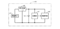
図1は本発明の第1の実施の形態に係るキーレスエントリシステムに使用されるキーの電源経路を示すブロック図である。このキーレスエントリシステムは、図3に示した従来のキーレスエントリシステムと同様に、キー(携帯器:図3中の符号1参照)側から自動車(図3中の符号7参照)側への片方向通信により無線でドアの解錠を行うものであって、特に、無線通信に際してキー1の電池切れを心配する必要がないように、図1のように熱電素子41を使用した体温発電システムにより電力供給を行うものである。尚、図1に示したキー43は図3中のキー1に相当し、図1中の無線回路45は図3中の300MHz帯送信部5に相当する。
{First embodiment}
<Configuration>
FIG. 1 is a block diagram showing a power path of a key used in the keyless entry system according to the first embodiment of the present invention. As in the conventional keyless entry system shown in FIG. 3, this keyless entry system is unidirectional from the key (portable device: see reference numeral 1 in FIG. 3) to the automobile (see
具体的に、この実施形態のキーレスエントリシステムでは、図3に示した従来技術1と同様に、キー1側のスイッチ3を押すことにより、このスイッチ3からのトリガ信号が300MHz帯送信部5に入力され、この300MHz帯送信部5から自動車7側の300MHz帯受信部9に対して、キー1側内に予め記憶しておいたIDの情報を含めた無線信号が送信される。
Specifically, in the keyless entry system according to this embodiment, the trigger signal from the switch 3 is sent to the 300
そして、自動車7側においては、図3の如く、300MHz帯受信部9が無線信号を受信した時点で、その中に含まれるIDの情報を、マイコン等を有する施解錠制御手段11に伝送する。施解錠制御手段11は、IDの認証を行った後、アクチュエータ13のドアの解錠(アンロック)の駆動制御を行う。
On the
そして、このキーレスエントリシステムに使用されるキー43は、図1の如く、自動車7側に対して無線通信を行う無線回路45(図3中の300MHz帯送信部5に相当する)と、無線回路45で無線通信するID情報等のデータが予め格納された記憶部47と、ユーザーの体温を電力に変換する熱電素子41と、この熱電素子41で得られた電圧を昇圧制御する昇圧制御IC49と、電池51とを備える。
As shown in FIG. 1, a
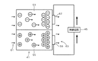
ここで、熱電素子41は、2種類の金属や半導体の接合部に生じる温度により電位差が発生する「ゼーベック効果」を利用して、人の体温と外気温との温度差により発電を行うものであり、例えば図2の如く、n型半導体53と、このn型半導体53に接合されたp型半導体55と、各半導体53,55の放熱側に形成された電極57,59とを備える。そして、互いに接合された両半導体53,55の一端を体温61で過熱したとき、ゼーベック効果により各半導体53,55の内部のイオンが放熱側に移動し、よってその放熱側に形成された両電極57,59に電位差が発生するため、これを発電電圧として無線回路45に印加する。ただし実際には、図1の如く、昇圧制御IC49により熱電素子41からの電圧が昇圧されてから無線回路45に印加される。
Here, the
そして、熱電素子41は、キー1側のスイッチ3の表面等、スイッチ3自体の構成部品として構成されてもよいし、あるいはスイッチ3の近傍など、ユーザーの手での接触が容易な位置に配置される。
The
<動作>
上記構成のキーレスエントリシステムを用いた搭乗時の動作を説明する。まず搭乗者は、図3の如く、キー1側のスイッチ3を押すことにより、このスイッチ3からのトリガ信号が300MHz帯送信部5(無線回路45)に入力される。
<Operation>
The operation at the time of boarding using the keyless entry system having the above configuration will be described. First, as shown in FIG. 3, when the passenger presses the switch 3 on the key 1 side, a trigger signal from the switch 3 is input to the 300 MHz band transmitter 5 (wireless circuit 45).
この際、搭乗者が熱電素子41に手を触れなかったときには、図1に示した電池51から無線回路45(300MHz帯送信部5)及び記憶部47に給電がなされる。
At this time, when the passenger does not touch the
一方、搭乗者が熱電素子41を手で触った場合は、その体温が図2に示した熱電素子41の一端に伝達される。そうすると、ゼーベック効果により各半導体53,55の内部のイオンが放熱側に移動し、よってその放熱側に形成された両電極57,59に電位差が発生する。かかる電位差を発電電圧として、図1に示した昇圧制御IC49で昇圧した後、無線回路45(300MHz帯送信部5)及び記憶部47への給電がなされる。
On the other hand, when the passenger touches the
そして、300MHz帯送信部5からは、例えば記憶部47内に予め格納されたID情報等を含めて、自動車7側の300MHz帯受信部9に対して無線信号が送信される。
Then, a radio signal is transmitted from the 300 MHz
そして、自動車7側においては、図3の如く、300MHz帯受信部9が無線信号を受信した時点で、その中に含まれるIDの情報を、マイコン等を有する施解錠制御手段11に伝送する。施解錠制御手段11は、IDの認証を行った後、アクチュエータ13のドアの解錠(アンロック)の駆動制御を行う。
On the
また、無線回路45が非使用の時点で熱電素子41の発電が行われた場合は、かかる発電電圧が電池51に印加されて蓄電に供される。
Further, when the
以上のように、このキーレスエントリシステムでは、ユーザーが所持するキー(図3中の符号1)の電池切れを心配することなく、体温を伝達するだけで、キー43から自動車7側に対する無線送信を行ってドアの解錠を行うことができるので、もしものときのキーの電池切れやメカニカルキーがない場合の安心感を得ることができる。
As described above, in this keyless entry system, wireless transmission from the key 43 to the
特に、誘導給電を利用せずに効率よくドアの解錠を行うことができるので、電磁波発振装置を搭載するためのスペースが必要なく、しかも、電磁波発振装置を稼動させるための多大な電力を必要としないので便利である。 In particular, the door can be unlocked efficiently without using inductive power supply, so there is no need for a space for mounting the electromagnetic wave oscillation device, and much power is required to operate the electromagnetic wave oscillation device. It is convenient because it does not.
{第2の実施の形態}
<構成>
本発明の第2の実施の形態に係るキーレスエントリシステムは、図4に示した従来のキーレスエントリシステムと同様に、キー(携帯器:図4中の符号21参照)側と自動車(図4中の符号23参照)側と間の双方向通信により無線でドアの解錠を行うものであって、特に、無線通信に際してキー21の電池が切れた場合に、この電池の代替エネルギーとして、図1に示した第1の実施の形態と同様に、熱電素子41を使用した体温発電システムにより電力供給を行うものである。尚、図1に示したキー43は図4中のキー21に相当し、図1中の無線回路45は図4中の100MHz帯受信部29及び300MHz帯送信部31に相当する。
{Second Embodiment}
<Configuration>
The keyless entry system according to the second embodiment of the present invention is similar to the conventional keyless entry system shown in FIG. 4 in that the key (portable device: see
具体的に、この実施形態のキーレスエントリシステムでは、図4に示した従来技術2と同様に、運転者等がキー21を携帯した状態で、ドアノブに設置された感熱センサ等のタッチセンサを触ったり、ドアノブの近傍に配置された押し釦式スイッチを押したり、あるいはキー21が自動車23側を中心とする一定範囲内に近づくだけで、自動車23側がその旨を判断して自動的にドアの解錠(アンロック)を行うもので、自動車23側に設置されたトリガ手段25からのトリガ信号が100kHz帯送信部27に入力されると、この100kHz帯送信部27から100kHz帯の信号がキー21側に内蔵された100kHz帯受信部29に無線送信され、これを契機として、キー21側に内蔵された300MHz帯送信部31から自動車23側の300MHz帯受信部33に対して、キー21側内に予め記憶しておいたIDの情報を含めた無線信号が送信される。そして、自動車23側においては、300MHz帯受信部33が無線信号を受信した時点で、その中に含まれるIDの情報を、マイコン等を有する施解錠制御手段35に伝送する。施解錠制御手段35は、IDの認証を行った後、アクチュエータ37のドアの解錠(アンロック)の駆動制御を行うようになっている。
Specifically, in the keyless entry system of this embodiment, the driver touches a touch sensor such as a thermal sensor installed on the door knob while carrying the key 21 in the same manner as in the related art 2 shown in FIG. Or by pushing a push button type switch arranged in the vicinity of the door knob, or the key 21 approaches only within a certain range centered on the
そして、このキーレスエントリシステムに使用されるキー43は、第1の実施の形態と同様に、図1の如く、自動車7側に対して無線通信を行う無線回路45(図4中の300MHz帯送信部5に相当する)と、無線回路45で無線通信するID情報等のデータが予め格納された記憶部47と、ユーザーの体温を電力に変換する熱電素子41と、この熱電素子41で得られた電圧を昇圧制御する昇圧制御IC49と、電池51とを備える。
As in the first embodiment, the key 43 used in this keyless entry system is a wireless circuit 45 (300 MHz band transmission in FIG. 4) that performs wireless communication with the
ここで、熱電素子41が「ゼーベック効果」を利用して発電する点は第1の実施の形態と同様であり、その構成原理は図2の通りである。
Here, the point that the
<動作>
上記構成のキーレスエントリシステムを用いた搭乗時の動作を説明する。
<Operation>
The operation at the time of boarding using the keyless entry system having the above configuration will be described.
まず、キー43(21)内の電池51が充電状態にある場合について説明する。この場合は、図4において、キー21側の100kHz帯受信部29及び300MHz帯送信部31は、電池51からの給電を受けて動作する。
First, the case where the
即ち、自動車23側に設置されたトリガ手段25からのトリガ信号が100kHz帯送信部27に入力されると、この100kHz帯送信部27から100kHz帯の信号がキー21側に内蔵された100kHz帯受信部29に無線送信される。
That is, when a trigger signal from the trigger means 25 installed on the
搭乗者は、キー21(43)を手で触ることなく、例えばポケットや鞄内に収納したままであっても、100kHz帯送信部27からの信号を100kHz帯受信部29で受信した時点で、キー21側内に予め記憶しておいたIDの情報を含めた無線信号が300MHz帯送信部31から自動車23側の300MHz帯受信部33に自動的に送信される。
Even when the passenger does not touch the key 21 (43) with his / her hand, for example, while keeping it in a pocket or a bag, the passenger receives the signal from the 100 kHz
そして、自動車23側においては、300MHz帯受信部33が無線信号を受信した時点で、その中に含まれるIDの情報を、マイコン等を有する施解錠制御手段35に伝送する。施解錠制御手段35は、IDの認証を行った後、アクチュエータ37のドアの解錠(アンロック)の駆動制御を行う。
On the
しかしながら、キー43(21)内の電池51が切れている場合、即ち電池の出力電圧が低下した場合は、100kHz帯送信部27から100kHz帯の信号が送られてきても、キー21側の100kHz帯受信部29は無線信号を受信できず、また300MHz帯送信部31の動作できないことから、自動的なドアの解錠は行われない。
However, when the
そこで、搭乗者は、キー43を手で握るなどして、体温をキー43の熱電素子41に伝達する。そうすると、熱電素子41が発電し、図1に示した昇圧制御IC49で昇圧した後、無線回路45に印加される。
Therefore, the passenger transmits the body temperature to the
以上のように、このキーレスエントリシステムでは、ユーザーが所持するキー43(図1:図4中の符号21参照)の電池51が充分である場合には、キー43に手を一切触れることなく、ドアの解錠を行うことができる一方、キー43の電池51の出力電圧が低下した場合には、そのキー43に手を触れて体温を伝達するだけで、キー43から自動車7側に対する無線送信を行ってドアの解錠を行うことができる。したがって、もしものときのキー43の電池51の出力電圧が低下した場合に、しかもメカニカルキーを所持していない場合にも、支障無くドアの解錠を行うことができる。
As described above, in this keyless entry system, when the
特に、誘導給電を利用せずに効率よくドアの解錠を行うことができるので、電磁波発振装置を搭載するためのスペースが必要なく、しかも、電磁波発振装置を稼動させるための多大な電力を必要としないので便利である。 In particular, the door can be unlocked efficiently without using inductive power supply, so there is no need for a space for mounting the electromagnetic wave oscillation device, and much power is required to operate the electromagnetic wave oscillation device. It is convenient because it does not.
また、電池51として蓄電池を使用する場合は、この電池51が切れても、熱電素子41での発電電圧を電池51に印加することで、この電池51の充電を容易に行うことかでき便利である。
In addition, when a storage battery is used as the
尚、上記第1の実施の形態では、ドアの解錠のみを説明したが、さらにこのドアの解錠に付随して、エンジンの始動を自動的に開始してもよい。これにより、メカニカルキーを忘れて搭乗しようとした場合にも、エンジン始動までメカニカルキー無しで実行させることができる便利である。ただし、この場合のエンジン始動は、セキュリティ状の安全性等を考慮して、1回だけに限定して許可を行うことが望ましい。 In the first embodiment, only the unlocking of the door has been described, but the engine may be automatically started in association with the unlocking of the door. Thereby, even if the user forgets the mechanical key and tries to board, it is convenient that the engine can be executed without the mechanical key until the engine is started. However, in this case, it is desirable that the engine start is permitted only once in consideration of security safety.
1,21,43 キー
11,35 施解錠制御手段
13,37 アクチュエータ
7,23 自動車
25 トリガ手段
27 帯送信部
29 帯受信部
3 スイッチ
41 熱電素子
45 無線回路
47 記憶部
51 電池
1, 21, 43
Claims (3)
前記携帯器と、
自動車内に設置され、前記携帯器からの無線信号を受信してドアの解錠を制御する施解錠制御手段と
を備え、
前記携帯器は、
前記自動車に対して通信するための無線回路と、
少なくとも少なくとも体温により電力を発電して前記無線回路に給電する熱電素子と
を備えるキーレスエントリシステム。 A keyless entry system for unlocking an automobile door by a wireless signal from a portable device carried by a user,
The portable device;
An unlocking control unit that is installed in an automobile and receives a radio signal from the portable device to control unlocking of the door;
The portable device is
A radio circuit for communicating with the vehicle;
A keyless entry system comprising at least a thermoelectric element that generates electric power at least at a body temperature and supplies power to the wireless circuit.
携帯器は、前記無線回路の前記自動車に対する通信を操作するためのスイッチをさらに備え、
前記熱電素子は、前記スイッチ自体の構成部品として、または前記スイッチの近傍に設置されることを特徴とするキーレスエントリシステム。 The keyless entry system according to claim 1,
The portable device further includes a switch for operating communication of the wireless circuit to the vehicle,
The keyless entry system, wherein the thermoelectric element is installed as a component of the switch itself or in the vicinity of the switch.
前記携帯器は電池を備え、
前記携帯器の前記無線回路は、前記自動車からの無線信号を受信し、且つこの受信に応じて前記自動車に対する無線信号を送信し、
前記熱電素子は、前記電池と並列して前記無線回路に電圧を印加することを特徴とするキーレスエントリシステム。 The keyless entry system according to claim 1,
The portable device includes a battery,
The wireless circuit of the portable device receives a wireless signal from the vehicle, and transmits a wireless signal to the vehicle in response to the reception,
The keyless entry system, wherein the thermoelectric element applies a voltage to the wireless circuit in parallel with the battery.
Priority Applications (1)
| Application Number | Priority Date | Filing Date | Title |
|---|---|---|---|
| JP2004109836A JP2005290901A (en) | 2004-04-02 | 2004-04-02 | Keyless entry system |
Applications Claiming Priority (1)
| Application Number | Priority Date | Filing Date | Title |
|---|---|---|---|
| JP2004109836A JP2005290901A (en) | 2004-04-02 | 2004-04-02 | Keyless entry system |
Publications (1)
| Publication Number | Publication Date |
|---|---|
| JP2005290901A true JP2005290901A (en) | 2005-10-20 |
Family
ID=35324143
Family Applications (1)
| Application Number | Title | Priority Date | Filing Date |
|---|---|---|---|
| JP2004109836A Pending JP2005290901A (en) | 2004-04-02 | 2004-04-02 | Keyless entry system |
Country Status (1)
| Country | Link |
|---|---|
| JP (1) | JP2005290901A (en) |
Cited By (5)
| Publication number | Priority date | Publication date | Assignee | Title |
|---|---|---|---|---|
| US8260166B2 (en) * | 2007-05-24 | 2012-09-04 | Ricoh Company, Limited | Image forming apparatus and electric appliance including a thermoelectric element |
| GB2529141A (en) * | 2014-07-09 | 2016-02-17 | Paresh Jogia | Body heat powered wireless transmitter |
| DE102008024958B4 (en) | 2008-05-23 | 2018-03-22 | Conti Temic Microelectronic Gmbh | Electronic key |
| JP2020045636A (en) * | 2018-09-14 | 2020-03-26 | 東芝情報システム株式会社 | Activation / passive system |
| WO2020121733A1 (en) * | 2018-12-10 | 2020-06-18 | 日本電気株式会社 | Transmission device |
-
2004
- 2004-04-02 JP JP2004109836A patent/JP2005290901A/en active Pending
Cited By (5)
| Publication number | Priority date | Publication date | Assignee | Title |
|---|---|---|---|---|
| US8260166B2 (en) * | 2007-05-24 | 2012-09-04 | Ricoh Company, Limited | Image forming apparatus and electric appliance including a thermoelectric element |
| DE102008024958B4 (en) | 2008-05-23 | 2018-03-22 | Conti Temic Microelectronic Gmbh | Electronic key |
| GB2529141A (en) * | 2014-07-09 | 2016-02-17 | Paresh Jogia | Body heat powered wireless transmitter |
| JP2020045636A (en) * | 2018-09-14 | 2020-03-26 | 東芝情報システム株式会社 | Activation / passive system |
| WO2020121733A1 (en) * | 2018-12-10 | 2020-06-18 | 日本電気株式会社 | Transmission device |
Similar Documents
| Publication | Publication Date | Title |
|---|---|---|
| JP5313701B2 (en) | Vehicle door handle and locking system | |
| US6323566B1 (en) | Transponder for remote keyless entry systems | |
| US11781350B2 (en) | Emergency actuating device for a movable part of a vehicle | |
| EP0848123B1 (en) | A remote keyless entry system | |
| JP2002525702A (en) | Electronic communication system | |
| JP2004003161A (en) | Electronic key system | |
| CN110944884B (en) | Mobile identification transmitter | |
| CN104114415B (en) | Method for the portable identification sensor of passive access system of motor vehicles and energy-saving operation identification sensor | |
| JP2005290901A (en) | Keyless entry system | |
| EP1969566B1 (en) | Method for passive keyless entry of a motor vehicle especially of an industrial vehicle | |
| KR20100079606A (en) | Smart key system | |
| CN102092432B (en) | Antitheft apparatus for equipment with prime mover | |
| JP5573072B2 (en) | Smart entry system | |
| CN113202363A (en) | Locking and unlocking assembly and door handle assembly | |
| JP2010127036A (en) | Portable machine used for keyless entry system for vehicle | |
| JP2019085777A (en) | Electronic key and electronic key system | |
| KR20100079603A (en) | Smart key system and management method of the same | |
| CN104903937A (en) | System with a security device and a drive for opening a movable motor vehicle part | |
| JP2006312821A (en) | Vehicle door unlocking device | |
| JP2007297774A (en) | Door lock controller | |
| JPH11256900A (en) | Portable operation device, in-vehicle control device, and vehicle operation management system | |
| JPH09105255A (en) | Control system for vehicle | |
| JP2008127777A (en) | Keyless system for vehicle | |
| KR100797133B1 (en) | Charging system with battery self-diagnosis and charging function | |
| JP2010042777A (en) | Antitheft device |