JP2005290889A - Structure of depressed road and its execution method - Google Patents
Structure of depressed road and its execution method Download PDFInfo
- Publication number
- JP2005290889A JP2005290889A JP2004108945A JP2004108945A JP2005290889A JP 2005290889 A JP2005290889 A JP 2005290889A JP 2004108945 A JP2004108945 A JP 2004108945A JP 2004108945 A JP2004108945 A JP 2004108945A JP 2005290889 A JP2005290889 A JP 2005290889A
- Authority
- JP
- Japan
- Prior art keywords
- road
- pile
- digging
- traffic
- construction
- Prior art date
- Legal status (The legal status is an assumption and is not a legal conclusion. Google has not performed a legal analysis and makes no representation as to the accuracy of the status listed.)
- Granted
Links
- 238000000034 method Methods 0.000 title claims description 46
- 230000000994 depressogenic effect Effects 0.000 title abstract 6
- 238000010276 construction Methods 0.000 claims abstract description 70
- 238000009412 basement excavation Methods 0.000 claims description 42
- 210000000779 thoracic wall Anatomy 0.000 claims description 19
- 239000000463 material Substances 0.000 claims description 9
- 230000000694 effects Effects 0.000 abstract description 4
- XLYOFNOQVPJJNP-UHFFFAOYSA-N water Substances O XLYOFNOQVPJJNP-UHFFFAOYSA-N 0.000 abstract description 4
- 239000004567 concrete Substances 0.000 description 12
- 239000003673 groundwater Substances 0.000 description 5
- 230000003014 reinforcing effect Effects 0.000 description 4
- 238000004132 cross linking Methods 0.000 description 2
- 238000007667 floating Methods 0.000 description 2
- 239000007787 solid Substances 0.000 description 2
- 210000001015 abdomen Anatomy 0.000 description 1
- 238000005452 bending Methods 0.000 description 1
- 230000000903 blocking effect Effects 0.000 description 1
- 238000005260 corrosion Methods 0.000 description 1
- 230000007797 corrosion Effects 0.000 description 1
- 238000005553 drilling Methods 0.000 description 1
- 238000005516 engineering process Methods 0.000 description 1
- 238000009434 installation Methods 0.000 description 1
- NJPPVKZQTLUDBO-UHFFFAOYSA-N novaluron Chemical compound C1=C(Cl)C(OC(F)(F)C(OC(F)(F)F)F)=CC=C1NC(=O)NC(=O)C1=C(F)C=CC=C1F NJPPVKZQTLUDBO-UHFFFAOYSA-N 0.000 description 1
- 238000003825 pressing Methods 0.000 description 1
- 239000011513 prestressed concrete Substances 0.000 description 1
- 238000009751 slip forming Methods 0.000 description 1
- 239000004575 stone Substances 0.000 description 1
Images

Landscapes
- Road Paving Structures (AREA)
- Bridges Or Land Bridges (AREA)
Abstract
Description
本発明は、半地下の交通路である掘割道路の構造とその施工方法に関する。 The present invention relates to a structure of a digging road that is a semi-underground traffic road and a construction method thereof.
従来、掘割道路の構造としては、溝状に掘削された地盤に、U字形のコンクリート構造物を構築した構造が知られている。
この掘割道路を施工する方法としては、まず交通路となる部分の両側に土留壁を設置した後に掘削を行うとともに上部に覆工を敷設し、U字型のコンクリート構造物を構築する工法が知られている。
また、掘割道路のうち、他の交通路との交差がある部分(立体交差)には、U字形のコンクリート構造物のかわりに、ボックスカルバートを用いることで立体交差を構築している。
Conventionally, as a structure of a digging road, a structure in which a U-shaped concrete structure is constructed on a ground excavated in a groove shape is known.
As a method of constructing this excavation road, there is a known method of constructing a U-shaped concrete structure by first excavating after installing retaining walls on both sides of the part that becomes the traffic road and laying a lining on the upper part. It has been.
In addition, a three-dimensional intersection is constructed by using a box culvert instead of a U-shaped concrete structure at a portion of the digging road where there is an intersection with another traffic road (three-dimensional intersection).
その他、立体交差を構築する工法としては、例えば、断面形状が矩形状のシールドによって路下にトンネルを構築することで立体交差とする工法(例えば、非特許文献1、2参照)や、打設した杭の上部に、上側となる交通路を構築して上側の交通路を通行可能とした後、下側を掘削して立体交差とする工法(例えば、特許文献1参照)が提案されている。
交通路を開削してコンクリート構造物の設置を行う工法では、車線の規制が多くなるとともに工期が長いため、交通渋滞の原因となっていた。
また、立体交差部分において、ボックスカルバートを用いる工法やシールド工法は、下側を通る交通路の上部にある程度の土被りが必要なため、その分だけ交通路の深度が深くなり、地下部分の道路延長が長くなるとともに、上載土圧に耐えうる構造にする必要がある。
特許文献1に示すような杭基礎を用いた工法では、杭の設置の他に、下側となる交通路の掘削の前に土留壁等の仮設工事の必要があるため、その分の工期、費用が必要であった。
また、いずれの工法においても、地下にある構造物には土圧や地下水圧がかかるため、仮設構造物及び地下構造物本体はこれに耐えうる強固な構造とする必要があり、これらを構築する部材のコストが高くなっていた。
The construction method that cuts off the traffic road and installs the concrete structure has caused traffic congestion due to increased lane restrictions and a longer construction period.
Also, in the three-dimensional intersection, the method using the box culvert and the shield method require a certain amount of earth covering the upper part of the traffic road that passes underneath, so that the depth of the traffic road becomes deeper and the road in the underground part It is necessary to make the structure long enough to withstand the overburden pressure.
In the construction method using a pile foundation as shown in
In any method, earth pressure and underground water pressure are applied to the structure under the ground, so the temporary structure and the underground structure main body need to have a strong structure that can withstand this. The cost of the member was high.
本発明の課題は、施工の際の仮設工事を削減して工期を短縮するとともに交通規制を削減し、掘割道路の構築工事による交通への影響を最小限とすることである。
また、掘割道路の構造において、仮設構造物及び地下構造物本体にかかる応力を分散し、これらを構築する部材のコストを削減することである。
It is an object of the present invention to reduce temporary construction during construction, shorten the construction period, reduce traffic regulations, and minimize the impact on traffic caused by construction work for excavated roads.
Moreover, in the structure of a digging road, it is to disperse the stress applied to the temporary structure and the underground structure main body, and to reduce the cost of members for constructing these.
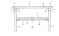
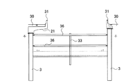
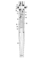
以上の課題を解決するため、請求項1に記載の発明は、例えば、図1、2、12に示すように、掘割道路1の両側に沿って土留壁となるように連続して設けた杭3と、
前記掘割道路1の両側に設けた前記杭3と連結し、前記掘割道路1をなす底版4とを備えることを特徴とする。
In order to solve the above problems, the invention described in
It connects with the said
このように、掘割道路1の両側に沿って土留壁となるように連続して杭3を設けたことで、杭3を土留壁と、掘割道路1の側壁とに兼用でき、土留壁と側壁を別々に構築する場合に比べ工期及び費用を削減できる。
また、従来土留壁は、側壁を構築する場所の外側に構築していたが、これらが同じ場所に構築されることとなるので、掘削幅を狭くできるとともに、施工ヤード27の幅を狭くでき、交通への影響を最小限にできる。
Thus, by providing the
In addition, the conventional retaining wall has been constructed outside the place where the side wall is constructed, but since these are constructed in the same place, the excavation width can be narrowed and the
さらに、掘割道路1をなす底版4を、両側の杭3と連結するように形成したことで、断面形状がH形となり、地下構造物が杭3による杭基礎と、底版4による直接基礎を併せ持つパイルドラフト構造を構成するようになる。これによって、地下水位が高い場所における躯体の浮き上がりや、地盤の液状化などに対しても安定した構造となる。
Furthermore, by forming the
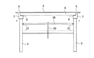
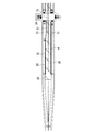
請求項2に記載の発明は、請求項1に記載の掘割道路の構造であって、例えば、図1、3、9に示すように、前記杭3の上部に、胸壁5を有し、前記胸壁5より前記掘割道路1側に橋座6を有する橋台7を設け、
前記掘割道路1の上部に設けられる上側の交通路2を形成する橋部材8を、前記掘割道路1を挟んで対向する前記橋座6に架設し、
前記胸壁5と前記橋部材8の端面との間で力の伝達を可能としたことを特徴とする。
Invention of
A
A force can be transmitted between the
このように、橋座6が胸壁5よりも掘割道路1側に有り、橋部材8を掘割道路1を挟んで対向する位置にある橋座6に架設し、胸壁5と橋部材8の端面との間で力の伝達を可能としたことで、橋部材8を杭3の切梁として利用できる。これにより、施工時において切梁36の仮設工事を削減できるとともに、完成後において、地下構造物にかかる土圧が底版4と橋部材8とに分散され、各部材にかかる負担を軽減でき、各部材のコストを削減できる。
また、橋部材8を架設することで上側の交通路2を形成するようにしたことで、掘割道路1を従来より浅い位置に構築でき、地下部分の道路延長を短くできるとともに各部材にかかる負担を軽減でき、各部材のコストを削減できる。
In this way, the
In addition, since the
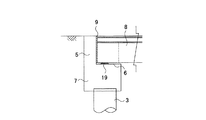
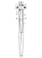
請求項3に記載の発明は、請求項2に記載の掘割道路の構造であって、例えば、図3に示すように、前記胸壁5と、前記橋部材8の端面との間に緩衝材9を備えることを特徴とする。
The invention according to
このように、胸壁5と橋部材8の端面との間に緩衝材9を備えることで、橋部材8に曲げモーメントを伝達することなく、軸方向の力のみを伝達できるようになる。この構造により、橋梁下部工としての杭3に過大な負担がかからないようにすることができる。
Thus, by providing the
請求項4に記載の発明は、掘割道路の施工方法であって、例えば図7から12に示すように、掘割道路1となる部分の両側に沿って土留壁となるように連続して杭3を設ける杭打設工程と、
前記掘割道路1となる部分を掘削する掘削工程と、
前記掘削工程によって掘削された掘削面に沿って、前記掘割道路1の両側に配された前記杭3と連結する底版4を形成する底版形成工程とを有することを特徴とする。
The invention according to
An excavation process for excavating the portion that becomes the
A bottom plate forming step of forming a
このような施工方法によれば、請求項1の効果と同様の効果を得ることができる。
According to such a construction method, the same effect as that of
請求項5に記載の発明は、請求項4に記載の掘割道路の施工方法であって、例えば、図9に示すように、前記杭3の上部に、胸壁5を有し、前記胸壁5より前記掘割道路1側に橋座6を有する橋台7を設け、前記掘割道路1の上部に設けられる上側の交通路2を形成する橋部材8を、前記掘割道路1を挟んで対向する前記橋座6に架設する橋掛け工程を、前記掘削工程の前に有することを特徴とする。
The invention according to
このような施工方法によれば、請求項2の効果と同様の効果を得ることができる。また、上側の交通路2は、この橋掛け工程によってほぼ完成し、完成後は、掘削工程中に施工前と同様に通行できるようになるので、交通への影響が少なくなる。
According to such a construction method, the same effect as that of
本発明によれば、掘割道路の両側に土留壁となるように連続して設けた杭が側壁としての機能も有し、また、橋部材が切梁としての機能も有することで、仮設工事を削減でき、工期、費用を削減できる。
また、地下構造物にかかる土圧を底版と橋部材とに分散し、各部材にかかる負担を軽減して、部材のコストを削減できる。
また、橋部材によって上側の交通路を形成するので、掘割道路を浅い位置に構築でき、地下部分の道路延長を短くできるとともに、各部材にかかる負担を軽減して、部材のコストを削減できる。
さらに、地下構造物がパイルドラフト構造を有することで、地盤の液状化などに対しても安定な構造となる。
According to the present invention, the piles continuously provided so as to be retaining walls on both sides of the digging road also have a function as a side wall, and the bridge member also has a function as a cut beam. Can reduce the construction period and cost.
Moreover, the earth pressure concerning an underground structure can be disperse | distributed to a bottom slab and a bridge member, the burden concerning each member can be reduced, and the cost of a member can be reduced.
Moreover, since the upper traffic road is formed by the bridge member, the excavation road can be constructed at a shallow position, the road extension of the underground portion can be shortened, and the burden on each member can be reduced, thereby reducing the cost of the member.
Furthermore, since the underground structure has a piled raft structure, the structure is stable against liquefaction of the ground.
以下、図を参照して本発明を実施するための最良の形態を詳細に説明する。
掘割道路は、道路や線路などの交通路が半地下となったものであって、ここでは、その掘割道路の一例として、図12に示すような交通路の交差部18における立体交差の構造及び施工方法について説明する。
Hereinafter, the best mode for carrying out the present invention will be described in detail with reference to the drawings.
The digging road is a semi-underground traffic road such as a road or a railroad. Here, as an example of the digging road, the structure of a three-dimensional intersection at a
この立体交差は、交差する交通路としての道路を立体的に交差させるもので、下側を通る交通路が地下を通る掘割道路となったものである。図1から図12に示すように、掘割道路1の両側には、地下部分の始点から終点まで連続して杭3をなす杭材が設けられている。この杭3は、隣接する杭3同士が継手(図示略)によって連結しており、掘割道路1の側壁をなすとともに土留壁をなすものである。この土留壁をなす杭3は、この立体交差の構築時において、掘割道路1を掘削するときに設けられたものであり、これをそのまま掘割道路1の側壁として用いることで、工期の短縮及び費用の削減が可能となる。
This three-dimensional intersection is a three-dimensional intersection of roads as intersecting traffic roads, and a traffic road passing underneath becomes a digging road that passes underground. As shown in FIGS. 1 to 12, on both sides of the
この連続して打設された杭3の間にある掘割道路1の下部には、底版4が形成されている。杭3の外面には、杭3と底版4を連結する連結部材としての鉄筋(図示略)が、底版4の方向に向かって突出するように溶接されており、この鉄筋が底版4の鉄筋の一部となることによって、杭3と底版4が強固に連結されている。すなわち、図1、2に示すように、杭3と底版4で断面がH形となった構造をしており、この立体交差の地下構造物は、杭3による杭基礎と、底版4による直接基礎とを併せ持つパイルドラフト構造となっている。このように、地下構造物がパイルドラフト構造となっていることで、例えば、地下水位が高い場所における躯体の浮き上がりによって、地下構造物が上方向の力を受けても、杭3の引抜抵抗により耐えることができる。また、支持杭を有することで、地盤の液状化に対しても有効である。
A
なお、掘割道路1の両側に設けられた杭3のうち、地下部分の始点、終点付近であって、底版4の下面よりも地下水位が低く、地下水の影響をあまり受けない範囲では、杭3と底版4を連結せず、自立式の杭としても良い。
In addition, among the
図12に示すような交通路の交差部18にある杭3の上部には、図1に示すように橋台7が設けられており、ここに上側の交通路2をなす橋部材8が架設されている。この橋台7の上部には、図1、3、4に示すように、掘割道路1に対して外側にあって、上方へ鉛直に突出する胸壁5が掘割道路1の延長方向に沿って設けられており、橋台7の断面形状はL字形となっている。また、橋台7の上部であって、この胸壁5よりも掘割道路1側には、橋部材8を載置する水平面を有する橋座6が形成されている。さらに、この橋座6の上面には、橋部材8を支持するゴム支承19が設けられており、橋部材8は、掘割道路1を挟んで対向する位置にある橋座6に、ゴム支承19を介して架設される。
As shown in FIG. 1, an
橋部材8としては、プレテンション方式プレストレストコンクリート製のもの(プレテン桁)で、あらかじめ工場などで生産されたものを用いている。このようなプレテン桁としては、例えば、T桁やホロー桁のような一般的に用いられているものを用いることができる。図1、3、4、5では、T桁を用いた場合を図示したが、その他の桁を用いた場合もこれとほぼ同様の構成となっている。
橋部材8は、長さ方向が掘割道路1の延長方向に対して直交するように、胸壁5より掘割道路1側にある橋座6に設けられたゴム支承19に載置されている。そして、隣接して複数本配された橋部材8の上面は舗装され、上側の交通路2となっている。
また、隣接して配された橋部材8の間には、橋部材8どうしを連結するようにコンクリートが充填されているとともに、このコンクリート部分と橋台7を連結するようにアンカーバー20が設けられ、橋台7から橋部材8が外れないようにしている。
なお、ゴム支承19とアンカーバー20はともに、掘割道路1を挟んだ両側の橋台7に設けられているが、アンカーバー20の構造は、掘割道路1を挟んだ片側が固定側、これに対向する側が可動側となっている。すなわち、固定側では、アンカーバー20が橋部材8どうしの間に充填されたコンクリート部分に固定されており、可動側ではアンカーバー20とコンクリート部分との間に遊間が設けられている。
The
The
Further, between the
The
この橋部材8は上側の交通路2を形成するほか、土留壁をなす杭3の切梁としても機能するものである。このように橋部材8が土留壁の切梁を兼ねることで、底版4や杭3にかかる応力が分散されて、各部材の負担が軽減されるので、各部材のコストを削減できる。
しかし、橋部材8であるプレテン桁は、もともと外部から過大な軸力が加わることを想定して作られていないので、過分に負担させるわけにはいかない。そこで、掘削時には、図5に示すように、橋部材8を単独で切梁とせず、仮設の切梁36も設けて橋部材8の負担を軽減している。また、橋部材8の端面と胸壁5の間に緩衝材9を設けることで、橋部材8が緩衝材9を介して軸力のみを伝達する構造とし、この構造により、橋梁下部工としての杭3の負担を軽減している。
In addition to forming the
However, since the pretension girder as the
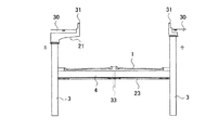
また、図2、12に示すように、橋部材8を載置している交差部18から所定の範囲には、掘割道路1の上部に突出するように設けられた張出し部21が設けられている。この張出し部21は、杭3に支持されるように杭3の上部に設けられており、側道30を走る車両のうち、交差点を右折する車両が待機する右折レーンをなすものである。なお、張出し部21を掘割道路1の延長方向に沿って連続して設け、交通路として利用できるようにしても良い。
As shown in FIGS. 2 and 12, an
次に、以上のような構成を有する掘割道路の一例である立体交差の施工方法について説明する。なお、交差部18を中心とした片側半分についての施工方法を示すが、反対側についても同様の施工を行うものとする。
まず、掘割道路1の両側に設けられる杭3の施工を行う。この杭3の施工にあたっては、杭上に配されて杭上を自走可能な杭打設装置を用いる。このような杭打設装置によって施工を行えば、施工ヤード27の範囲を狭くできるので、交通への影響を最小限に抑えることができる。また、杭打設装置を複数台投入し、各施工ヤード27で並行して施工を行えば、工期を短縮することができる。
また、ここでは、掘割道路1となる既存の交通路38が、4車線の交通路で、交差部18には右折レーンが設けられて5車線となっており、上側の交通路2となる既存の交通路39が、交差部18において3車線になっている交差点での施工について説明する。
Next, the construction method of the solid intersection which is an example of the digging road which has the above structures is demonstrated. In addition, although the construction method about the half of one side centering on the cross |
First, construction of the
Also, here, the existing
まず、図7に示すように、後に掘割道路1となる既存の交通路38のうち、交差部18を中心とした片側半分の施工を行う。
作業を行うための施工ヤード27としては、後に右折レーンとしての張出し部21を構築する部分とし、反対車線側もほぼ同じ範囲を施工ヤード27として確保する。よって、施工ヤード27の幅は、既存の交通路38のうち、最も外側にある車線部分と、その外側の杭3を施工するのに必要な部分とを合わせた幅となる。すなわち、二つの施工ヤード27の間には、既存の交通路38で内側の車線となっていた部分が残ることとなり、施工中であっても利用可能となっている。また、施工ヤード27を設けたことで利用できなくなった外側の車線は、施工ヤード27の外側に新たに構築した迂回路28に切り替える。この施工ヤード27の外側に新たに構築した迂回路28は、立体交差が完成した後に側道30を設ける部分を用いて仮設したものである。また、上側となる交通路39は交差部18のほぼ中央部まで設けられた施工ヤード27を迂回するように設けられる。
First, as shown in FIG. 7, half of one side of the existing
The
施工ヤード27や、迂回路28の仮設が完了したら、杭打設工程に移る。
上述の施工ヤード27内において、交差部18から順次杭3を施工し、後に橋部材8を載置する杭3には橋台7を形成する。この橋台7には、図3、4に示すように、胸壁5やゴム支承19及び橋部材8を橋台7に連結するためのアンカーバー20などが設けられる。そして、既存の交差部18にあって、橋台7を形成した杭3の上部を覆工部材29で覆工し、上側となる交通路39をここに移設する。同様に、交差部18を中心とした反対側の交通路についても同様の施工を行い、図8に示すように、上述した交差部18の覆工が完了したら、迂回させていた上側となる交通路39を元に戻す。
When the temporary construction of the
In the
次に、図8に示すように、施工ヤード27の長さを、地下部分の入口となる所まで延長し、杭3の施工を行うとともに、図2に示すように、施工した杭3の上部に側道30の側壁となる壁高欄31を形成する。
また、図12に示すように、後に掘割道路1の側道30の右折レーンとなる張出し部21の構築を行う。なお、この張出し部21は、次に行う橋掛け工程が完了してから使用開始とする。
Next, as shown in FIG. 8, the length of the
Moreover, as shown in FIG. 12, the overhang |
杭打設工程が完了したら、杭打設装置などを撤去し、図9に示すように、橋部材8を架設する橋掛け工程を行う。
橋部材8の架設は夜間において、杭3の施工時に施工ヤード27の間にあった交通路を通行止めとして、迂回路28のみを通行可能とする。そして、杭打設工程で、掘割道路となる交通路38の両側に打設した杭3の間を新たに施工ヤード32として行う。また、交差部18は、片側半分を施工ヤード32とし、上側となる交通路39は、この施工ヤード32を迂回するように仮設する。
When the pile placing process is completed, the pile placing apparatus and the like are removed, and a bridge process for constructing the
Construction of the
橋部材8の架設は、まず、施工ヤード32とした交差部18の覆工部材29を取り除くとともに、杭3の上部に形成した橋台7が露出する程度の深さだけ掘割道路となる交通路38を掘削する。この掘削した部分であって、掘割道路となる交通路38のほぼ中央に、後に仮設の切梁36を支持する中間杭33を、掘割道路となる交通路38の延長方向に並ぶように、適当な間隔を置いて打設する。中間杭33の打設後、橋台7の橋座6に設けられたゴム支承19に、あらかじめ工場などで製作された橋部材8であるプレテン桁をクレーン34によって載置するとともに、設置した橋部材8の端面と、胸壁5の間に緩衝材9を配置する。橋部材8を載置したら、隣接する橋部材8の間にコンクリートを充填する。これにより、橋部分が強固になるとともに、あらかじめ橋台7に設けられていたアンカーバー20がこのコンクリートによって固定され橋部材8と橋台7が連結される。なお、掘割道路1を挟んだ片側は可動側として、アンカーバー20の周囲に遊間ができるようにする。
その他、橋部材8の上面の舗装や橋側端部の壁高欄の構築等を行い、交通路として利用できるようにする。
First, the
In addition, pavement on the upper surface of the
上述の橋部材8の架設と同時に、橋部材8を架設する部分以外において、後の掘削工程のために、杭打設工程時の施工ヤード27の間にあった交通路38の撤去と、止水壁35、中間杭33の仮設を行う。交差部18を中心とした片側半分の橋掛け工程が完了したら、上側となる交通路39を、架設した橋部材8上を迂回するように架設し、反対側の施工を上述と同様に行い、橋掛け工程を完了する。
Simultaneously with the construction of the
図10に示すように、橋掛け工程の完了後、迂回させていた上側となる交通路39を元に戻す。
また、杭打設工程時に設けられた施工ヤード27では、杭3を打設するのに必要な範囲として、打設する杭3よりも外側に境界を有していたが、橋掛け工程時に設けられた施工ヤード32では、杭打設工程によって打設された杭3を境界としているため、側道部分が広くなっている。そこで、迂回路28を2車線にするとともに、張出し部21を右折レーンとして利用し、交通への影響を少なくする。そして、施工ヤード32を、後に地下部分を通る本線と側道30との分岐部分まで延長し、掘割道路となる交通路38の掘削工程を行う。
As shown in FIG. 10, after completion of the bridging process, the
In addition, the
図6に示すように、橋部材8を架設していないアプローチ部においては、掘削の進行に合わせ、土圧による杭3の変形を防止する切梁36を仮設する。この切梁36は、掘割道路1の延長方向に沿うように杭3に当接する腹起こし37に対して、水平に直交して当接するように配したもので、先に打設した中間杭33によってほぼ中央を支持されている。また、図5に示すように、橋部材8を架設した交差部18においては、橋部材8が切梁として機能するので、架設する切梁36は一段で良く、仮設工事を削減できる。所定の深さまで掘削を完了したら、掘割道路1をなす底版4を形成する底版形成工程に移る。
As shown in FIG. 6, in the approach portion where the
底版形成工程においては、まず、掘削面に砕石などからなる基礎部23を設ける。
次に、杭3の外面であって、底版4と接する部分には、杭3と底版4を連結する連結部材としての鉄筋(図示略)を、底版4が形成される方向に突出するように複数溶接する。
さらに、この鉄筋の他、底版4に必要な鉄筋を構築した後、コンクリートを打設して基礎部23の上部に底版4を構築する。コンクリートが硬化して杭3と底版4が連結し、杭基礎と直接基礎を併せ持つパイルドラフト構造が形成されたら、仮設していた切梁36を撤去する。なお、切梁36を支持していた中間杭33は底版4の上面で切断し、底版4の内部及び下部にあった部分はそのまま残置される。
In the bottom plate forming step, first, a
Next, a reinforcing bar (not shown) as a connecting member for connecting the
Further, in addition to this reinforcing bar, a reinforcing bar necessary for the
底版形成工程が完了したら、交通路の舗装や、排水設備、電気設備などの設置を行い、これらが完了したら、掘割道路1を開通させる。掘割道路1の開通に合わせて、掘割道路1の迂回路28を1車線にして側道30とし、歩道等を整備して施工完了となる。
When the bottom plate forming process is completed, the road is paved, drainage equipment, electrical equipment, etc. are installed, and when these are completed, the digging
なお、以上の実施の形態においては、交通路の交差部における立体交差について説明したが、本発明はこれに限定されるものではない。
例えば、自動車専用道路のように、半地下部分が長い距離連続する掘割道路を構築する場合も同様に杭打設工程、橋掛け工程、掘削工程、底版形成工程により構築することができる。このとき、掘割道路に交差する交通路が複数ある場合は、各箇所において橋掛け工程を行うようにする。また、橋掛け工程を掘割道路の所定区間に渡って連続して行い、掘割道路の上側に構築する交通路を掘割道路に並行するように構築しても良い。
In addition, although the above embodiment demonstrated the three-dimensional intersection in the intersection part of a traffic road, this invention is not limited to this.
For example, when constructing a digging road in which a semi-underground part continues for a long distance, such as an automobile exclusive road, it can be similarly constructed by a pile driving process, a bridging process, a digging process, and a bottom plate forming process. At this time, when there are a plurality of traffic roads intersecting the digging road, a bridging process is performed at each location. Further, the bridging process may be continuously performed over a predetermined section of the excavation road, and the traffic road constructed on the upper side of the excavation road may be constructed in parallel with the excavation road.
また、杭打設装置としては、例えば、杭上に配されて杭上を自走可能であり、既設の杭から反力を取って新たな杭を圧入する杭圧入装置等のような公知のものを用いても良い。
さらに、杭3と底版4とを連結する連結部材が、地下水等によって腐食することを防止するための止水手段を設けても良く、また、使用する橋部材、杭の材質、形状等も任意であって、その他、具体的な細部構造等についても適宜に変更可能であることは勿論である。
In addition, as a pile driving device, for example, a known pile pressing device that is arranged on a pile and is capable of self-propelling on the pile and presses a new pile by taking a reaction force from the existing pile. A thing may be used.
Furthermore, the connecting member that connects the
1 掘割道路
2 上側の交通路
3 杭
4 底版
5 胸壁
6 橋座
7 橋台
8 橋部材
9 緩衝材
18 交差部
DESCRIPTION OF
Claims (5)
前記掘割道路の両側に設けた前記杭と連結し、前記掘割道路をなす底版とを備えることを特徴とする掘割道路の構造。 Piles that are continuously provided so as to be retaining walls along both sides of the digging road;
A structure of a digging road, comprising a bottom slab connected to the piles provided on both sides of the digging road and forming the digging road.
前記掘割道路の上部に設けられる上側の交通路を形成する橋部材を、前記掘割道路を挟んで対向する前記橋座に架設し、
前記胸壁と前記橋部材の端面との間で力の伝達を可能としたことを特徴とする請求項1に記載の掘割道路の構造。 In the upper part of the pile, there is a chest wall, and an abutment having a bridge seat on the digging road side from the chest wall is provided,
The bridge member that forms the upper traffic road provided on the upper part of the digging road is installed on the bridge seat facing the digging road,
The structure of the digging road according to claim 1, wherein force can be transmitted between the chest wall and the end face of the bridge member.
前記掘割道路となる部分を掘削する掘削工程と、
前記掘削工程によって掘削された掘削面に沿って、前記掘割道路の両側に配された前記杭と連結する底版を形成する底版形成工程とを有することを特徴とする掘割道路の施工方法。 A pile driving process in which piles are continuously provided so as to become retaining walls along both sides of the portion to be the digging road;
An excavation process for excavating a portion to be the digging road;
A method for constructing a digging road, comprising: a bottom slab forming step for forming a bottom slab connected to the piles disposed on both sides of the digging road along the excavation surface excavated by the excavation process.
前記杭の上部に、胸壁を有し、前記胸壁より前記掘割道路側に橋座を有する橋台を設け、前記掘割道路の上部に設けられる上側の交通路を形成する橋部材を、前記掘割道路を挟んで対向する前記橋座に架設する橋掛け工程を、前記掘削工程の前に有することを特徴とする掘割道路の施工方法。 It is a construction method of the digging road according to claim 4,
An abutment having a battlement wall on the upper side of the pile, a bridge base having a bridge seat on the side of the excavation road from the battlement wall, and a bridge member forming an upper traffic path provided on the upper part of the excavation road, A construction method for a digging road, characterized in that it has a bridging step for erection on the bridge seat facing each other before the excavation step.
Priority Applications (1)
| Application Number | Priority Date | Filing Date | Title |
|---|---|---|---|
| JP2004108945A JP4406577B2 (en) | 2004-04-01 | 2004-04-01 | Digging road |
Applications Claiming Priority (1)
| Application Number | Priority Date | Filing Date | Title |
|---|---|---|---|
| JP2004108945A JP4406577B2 (en) | 2004-04-01 | 2004-04-01 | Digging road |
Publications (2)
| Publication Number | Publication Date |
|---|---|
| JP2005290889A true JP2005290889A (en) | 2005-10-20 |
| JP4406577B2 JP4406577B2 (en) | 2010-01-27 |
Family
ID=35324131
Family Applications (1)
| Application Number | Title | Priority Date | Filing Date |
|---|---|---|---|
| JP2004108945A Expired - Lifetime JP4406577B2 (en) | 2004-04-01 | 2004-04-01 | Digging road |
Country Status (1)
| Country | Link |
|---|---|
| JP (1) | JP4406577B2 (en) |
Cited By (8)
| Publication number | Priority date | Publication date | Assignee | Title |
|---|---|---|---|---|
| JP2007177446A (en) * | 2005-12-27 | 2007-07-12 | Ps Mitsubishi Construction Co Ltd | Coping concrete and its construction method |
| JP2007277996A (en) * | 2006-04-10 | 2007-10-25 | Mitsubishi Heavy Industries Bridge & Steel Structures Engineering Co Ltd | Three-dimensional viaduct approach section construction method and three-dimensional viaduct approach section structure |
| JP2007308995A (en) * | 2006-05-19 | 2007-11-29 | Kajima Corp | Underpass construction method and underpass |
| CN105887603A (en) * | 2016-05-11 | 2016-08-24 | 宁波市交通规划设计研究院有限公司 | Method for controlling differential settlement of bridgehead roadbed |
| CN105970755A (en) * | 2016-05-27 | 2016-09-28 | 宁波市交通规划设计研究院有限公司 | Construction method for prevention and treatment for sidewise slippage of soft soil roadbed |
| CN106192650A (en) * | 2016-07-27 | 2016-12-07 | 宁波市交通规划设计研究院有限公司 | The operation highway bridgehead vehicle jump coordinating to control based on malformation disposes structure and method |
| CN112391901A (en) * | 2020-10-20 | 2021-02-23 | 徐州中交徐盐高铁客运枢纽有限公司 | Temporary quick-building paving road for road traffic construction |
| CN114763685A (en) * | 2021-01-11 | 2022-07-19 | 新疆北新路桥集团股份有限公司 | Anti-deformation road structure |
Families Citing this family (3)
| Publication number | Priority date | Publication date | Assignee | Title |
|---|---|---|---|---|
| CN104131502A (en) * | 2014-07-07 | 2014-11-05 | 广东盛瑞土建科技发展有限公司 | Construction method for widening road in rapid erection manner |
| CN106835879B (en) * | 2017-01-23 | 2019-07-05 | 安徽省交通规划设计研究总院股份有限公司 | Highway is laterally without support type peg board formula without dirt road base and its construction method |
| CN107326807B (en) * | 2017-07-13 | 2019-02-05 | 浙江永联建设工程股份有限公司 | A kind of construction technology of frame core-tube system |
-
2004
- 2004-04-01 JP JP2004108945A patent/JP4406577B2/en not_active Expired - Lifetime
Cited By (10)
| Publication number | Priority date | Publication date | Assignee | Title |
|---|---|---|---|---|
| JP2007177446A (en) * | 2005-12-27 | 2007-07-12 | Ps Mitsubishi Construction Co Ltd | Coping concrete and its construction method |
| JP2007277996A (en) * | 2006-04-10 | 2007-10-25 | Mitsubishi Heavy Industries Bridge & Steel Structures Engineering Co Ltd | Three-dimensional viaduct approach section construction method and three-dimensional viaduct approach section structure |
| JP2007308995A (en) * | 2006-05-19 | 2007-11-29 | Kajima Corp | Underpass construction method and underpass |
| CN105887603A (en) * | 2016-05-11 | 2016-08-24 | 宁波市交通规划设计研究院有限公司 | Method for controlling differential settlement of bridgehead roadbed |
| CN105887603B (en) * | 2016-05-11 | 2018-06-19 | 宁波市交通规划设计研究院有限公司 | A kind of method for controlling Bridgehead by Blastig differential settlement |
| CN105970755A (en) * | 2016-05-27 | 2016-09-28 | 宁波市交通规划设计研究院有限公司 | Construction method for prevention and treatment for sidewise slippage of soft soil roadbed |
| CN106192650A (en) * | 2016-07-27 | 2016-12-07 | 宁波市交通规划设计研究院有限公司 | The operation highway bridgehead vehicle jump coordinating to control based on malformation disposes structure and method |
| CN106192650B (en) * | 2016-07-27 | 2018-05-15 | 宁波市交通规划设计研究院有限公司 | Coordinate the operation highway bridgehead vehicle jump disposal structure and method of control based on malformation |
| CN112391901A (en) * | 2020-10-20 | 2021-02-23 | 徐州中交徐盐高铁客运枢纽有限公司 | Temporary quick-building paving road for road traffic construction |
| CN114763685A (en) * | 2021-01-11 | 2022-07-19 | 新疆北新路桥集团股份有限公司 | Anti-deformation road structure |
Also Published As
| Publication number | Publication date |
|---|---|
| JP4406577B2 (en) | 2010-01-27 |
Similar Documents
| Publication | Publication Date | Title |
|---|---|---|
| US20060165489A1 (en) | Structure of intermediate wall of three arch excavated tunnel and method for constructing the same | |
| KR101344063B1 (en) | The construction method of steel-concrete underpass | |
| KR20160131410A (en) | Temporary construction and originally construction the outer layer of a 2-layer wall type underground road building method | |
| KR20100138122A (en) | Foundation and method of construction of underground arch ramen structure including composite composite arch structure | |
| KR101206860B1 (en) | Excavation tunnel constructing method using vertical side wall and arch ceiling | |
| JPH11152761A (en) | Underground structure and its construction method | |
| JP4406577B2 (en) | Digging road | |
| KR101040731B1 (en) | Mobile temporary facility for construction of composite composite arch structures | |
| JP4881555B2 (en) | Construction method of underground structure | |
| CN112983493A (en) | Reinforcing structure for shield to closely penetrate large-section bridge and culvert downwards and construction method | |
| KR100938395B1 (en) | Construction method of underground roadway using steel composite wall pile | |
| JP3586864B2 (en) | Underground structure construction method and elevated traffic path | |
| KR101293550B1 (en) | Construction method of underground structure | |
| KR101187369B1 (en) | Cip use of underground motorways construction work method | |
| KR100510092B1 (en) | A one-piece type arch-shaped structure with the precast concrete pannel and the steel frame under the earth, and method for manufacturing it | |
| JP2004332357A (en) | Construction method of flyover and flyover | |
| JP2013087516A (en) | Method of forming underground space under ground traffic road | |
| JP4263935B2 (en) | Construction method and elevated detour | |
| KR20070052109A (en) | Simultaneous construction of slab and exterior wall and underground reverse casting using slim composite floor structure | |
| JP2006112137A (en) | Branch tunnel junction structure and its construction method | |
| JP3146333B2 (en) | Tunnel construction method | |
| JP4939101B2 (en) | Approach construction method | |
| JP3619515B2 (en) | Split-bridge type traffic road and method for constructing split-bridge type traffic road | |
| CN207109624U (en) | The deep embeded type stake of culvert, compound contignation are set in a kind of karst region | |
| JP2007270566A (en) | Protective structure and its construction method |
Legal Events
| Date | Code | Title | Description |
|---|---|---|---|
| A621 | Written request for application examination |
Free format text: JAPANESE INTERMEDIATE CODE: A621 Effective date: 20070330 |
|
| A977 | Report on retrieval |
Free format text: JAPANESE INTERMEDIATE CODE: A971007 Effective date: 20081117 |
|
| A131 | Notification of reasons for refusal |
Free format text: JAPANESE INTERMEDIATE CODE: A131 Effective date: 20081125 |
|
| A521 | Request for written amendment filed |
Free format text: JAPANESE INTERMEDIATE CODE: A523 Effective date: 20090126 |
|
| A131 | Notification of reasons for refusal |
Free format text: JAPANESE INTERMEDIATE CODE: A131 Effective date: 20090728 |
|
| A521 | Request for written amendment filed |
Free format text: JAPANESE INTERMEDIATE CODE: A523 Effective date: 20090928 |
|
| TRDD | Decision of grant or rejection written | ||
| A01 | Written decision to grant a patent or to grant a registration (utility model) |
Free format text: JAPANESE INTERMEDIATE CODE: A01 Effective date: 20091027 |
|
| A01 | Written decision to grant a patent or to grant a registration (utility model) |
Free format text: JAPANESE INTERMEDIATE CODE: A01 |
|
| A61 | First payment of annual fees (during grant procedure) |
Free format text: JAPANESE INTERMEDIATE CODE: A61 Effective date: 20091109 |
|
| FPAY | Renewal fee payment (event date is renewal date of database) |
Free format text: PAYMENT UNTIL: 20121113 Year of fee payment: 3 |
|
| R150 | Certificate of patent or registration of utility model |
Ref document number: 4406577 Country of ref document: JP Free format text: JAPANESE INTERMEDIATE CODE: R150 Free format text: JAPANESE INTERMEDIATE CODE: R150 |
|
| FPAY | Renewal fee payment (event date is renewal date of database) |
Free format text: PAYMENT UNTIL: 20121113 Year of fee payment: 3 |
|
| FPAY | Renewal fee payment (event date is renewal date of database) |
Free format text: PAYMENT UNTIL: 20151113 Year of fee payment: 6 |
|
| R250 | Receipt of annual fees |
Free format text: JAPANESE INTERMEDIATE CODE: R250 |
|
| R250 | Receipt of annual fees |
Free format text: JAPANESE INTERMEDIATE CODE: R250 |
|
| R250 | Receipt of annual fees |
Free format text: JAPANESE INTERMEDIATE CODE: R250 |
|
| R250 | Receipt of annual fees |
Free format text: JAPANESE INTERMEDIATE CODE: R250 |
|
| R250 | Receipt of annual fees |
Free format text: JAPANESE INTERMEDIATE CODE: R250 |
|
| R250 | Receipt of annual fees |
Free format text: JAPANESE INTERMEDIATE CODE: R250 |
|
| EXPY | Cancellation because of completion of term |