JP2005290875A - Floor panel - Google Patents
Floor panel Download PDFInfo
- Publication number
- JP2005290875A JP2005290875A JP2004108576A JP2004108576A JP2005290875A JP 2005290875 A JP2005290875 A JP 2005290875A JP 2004108576 A JP2004108576 A JP 2004108576A JP 2004108576 A JP2004108576 A JP 2004108576A JP 2005290875 A JP2005290875 A JP 2005290875A
- Authority
- JP
- Japan
- Prior art keywords
- panel
- leg
- support
- unit panels
- floor
- Prior art date
- Legal status (The legal status is an assumption and is not a legal conclusion. Google has not performed a legal analysis and makes no representation as to the accuracy of the status listed.)
- Pending
Links
- 238000006073 displacement reaction Methods 0.000 claims abstract description 27
- 239000000463 material Substances 0.000 claims description 155
- 238000003780 insertion Methods 0.000 claims description 29
- 230000037431 insertion Effects 0.000 claims description 29
- 230000003014 reinforcing effect Effects 0.000 claims description 17
- 230000000379 polymerizing effect Effects 0.000 claims description 7
- 230000002787 reinforcement Effects 0.000 claims description 3
- 230000001629 suppression Effects 0.000 claims description 3
- 230000002093 peripheral effect Effects 0.000 description 43
- 238000010276 construction Methods 0.000 description 17
- 238000000034 method Methods 0.000 description 11
- 229920005989 resin Polymers 0.000 description 7
- 239000011347 resin Substances 0.000 description 7
- 238000000926 separation method Methods 0.000 description 6
- 229910052751 metal Inorganic materials 0.000 description 4
- 239000002184 metal Substances 0.000 description 4
- 230000004044 response Effects 0.000 description 4
- 229910000831 Steel Inorganic materials 0.000 description 3
- 230000004308 accommodation Effects 0.000 description 3
- 239000010959 steel Substances 0.000 description 3
- 229920003002 synthetic resin Polymers 0.000 description 3
- 239000000057 synthetic resin Substances 0.000 description 3
- 230000006872 improvement Effects 0.000 description 2
- 238000009434 installation Methods 0.000 description 2
- 230000000630 rising effect Effects 0.000 description 2
- 210000005182 tip of the tongue Anatomy 0.000 description 2
- 241000135309 Processus Species 0.000 description 1
- 229910052782 aluminium Inorganic materials 0.000 description 1
- XAGFODPZIPBFFR-UHFFFAOYSA-N aluminium Chemical compound [Al] XAGFODPZIPBFFR-UHFFFAOYSA-N 0.000 description 1
- 230000015572 biosynthetic process Effects 0.000 description 1
- 230000007547 defect Effects 0.000 description 1
- 230000005489 elastic deformation Effects 0.000 description 1
- 230000001747 exhibiting effect Effects 0.000 description 1
- 238000005194 fractionation Methods 0.000 description 1
- 238000001746 injection moulding Methods 0.000 description 1
- 230000001788 irregular Effects 0.000 description 1
- 238000012986 modification Methods 0.000 description 1
- 230000004048 modification Effects 0.000 description 1
- 238000000465 moulding Methods 0.000 description 1
- 238000005192 partition Methods 0.000 description 1
- 238000006116 polymerization reaction Methods 0.000 description 1
- 230000009466 transformation Effects 0.000 description 1
- 238000003466 welding Methods 0.000 description 1
Images


Landscapes
- Floor Finish (AREA)
Abstract
Description
本発明は、建築床面上に敷設され二重床を構成する床パネルに関するものである。 The present invention relates to a floor panel that is laid on a building floor and constitutes a double floor.
従来より、二重床を構成する床パネルとして、予め建築床面上の所定箇所に起立させて配設した支持脚に、平面視略方形状をなす一枚板状のパネル本体の各コーナー部をそれぞれ支持させて敷設する態様のものが知られている。しかし、一枚板状のパネル本体の各コーナー部のみに支持脚を固定して取り付けた場合、すなわち四点支持では、建築床面の不陸に起因してがたつきが生じ易いため、近時、パネル本体の所定部位に分画開口部を形成し、この分画開口部によって分画された単位パネルを分画開口部に沿って相対変位させることにより建築床面の不陸に沿って置き敷くことを可能にしているものが考えられている(例えば特許文献1参照)。
しかしながら、上述のものは、複数に分画された単位パネルを相対変位させることにより不陸に対応するように構成されているものの、予め支持脚を建築床面上の所定部位に配設し、その後パネル本体を支持脚に支持させるように取り付けなければならないため、部品点数が増加し、それに伴って施工作業が面倒であるという不具合が生じる。一方、このような不具合の発生を抑えるべく、パネル本体と支持脚とを予め組み付けた床パネルとすることも考えられるが、分画開口部によって分画された単位パネル同士が運搬時や施工時に分離するのを防止するために、例えば支持脚によって各単位パネル同士を自由度を持たせることなく緊密な状態で取り付けた場合には、単位パネル同士を相対変位させることが困難となり、その結果、床パネルとしての不陸に対する十分な追随性が得られないという不具合が生じ得る。 However, although the above is configured to cope with unevenness by relatively displacing the unit panels divided into a plurality, the support legs are arranged in advance on a predetermined part of the building floor, After that, since the panel body must be mounted so as to be supported by the support legs, the number of parts increases, resulting in a problem that the construction work is troublesome. On the other hand, in order to suppress the occurrence of such problems, it is conceivable to use a floor panel in which the panel body and support legs are pre-assembled. However, the unit panels separated by the separation opening are transported or constructed. In order to prevent separation, for example, when each unit panel is attached in a tight state without giving a degree of freedom by supporting legs, it becomes difficult to relatively displace the unit panels, and as a result, There may be a problem that sufficient followability with respect to unevenness as a floor panel cannot be obtained.
本発明は、このような課題に着目してなされたものであって、主たる目的は、部品点数の削減、及び施工作業の簡素化を実現するとともに、建築床面の不陸に対応させてがたつきを抑制することができる床パネルを提供することにある。 The present invention has been made paying attention to such problems, and its main purpose is to reduce the number of parts and simplify the construction work and to cope with the unevenness of the building floor. An object of the present invention is to provide a floor panel capable of suppressing the rattling.
すなわち、本発明の床パネルは、建築床面上に敷設され二重床を構成する床パネルであって、所定部位に形成した分画開口部によって分画された複数の単位パネルを有するパネル本体と、このパネル本体を支持し且つ前記建築床面に接地し得る第1支持脚とを具備してなり、前記パネル本体が、前記分画開口部を介して隣接する前記単位パネル同士を相対変位させ得るものであり、前記第1支持脚が、前記分画開口部を挟んで少なくとも2以上の前記単位パネルが隣接する部位に前記分画開口部を跨ぐように取り付けられ且つこれら隣接する単位パネルの各々と係り合うことでこれら単位パネル同士を連結するものであり、前記単位パネルと前記第1支持脚との間に、前記単位パネル同士の相対変位を許容する許容手段を設けていることを特徴とする。 That is, the floor panel of the present invention is a floor panel that is laid on a building floor and constitutes a double floor, and has a plurality of unit panels that are fractionated by a fractional opening formed in a predetermined portion. And a first support leg that supports the panel body and can be grounded to the building floor, and the panel body relatively displaces the adjacent unit panels through the fractional opening. The first support legs are attached so that at least two or more of the unit panels are adjacent to each other across the fraction opening, and the adjacent unit panels are disposed so as to straddle the fraction opening. The unit panels are connected to each other by being engaged with each other, and between the unit panels and the first support legs, an allowance means for allowing relative displacement between the unit panels is provided. Special To.
ここで「隣接する単位パネル同士の相対変位」とは、隣接する単位パネルの相対的な位置ずれによって生じるものであり、また、隣接する単位パネルの少なくとも一の単位パネルあるいは隣接する単位パネルの何れもが変形することによって生じるものである。また、「分画開口部」とは、パネル本体、或いは後述するパネル本体を構成する表材及び/又は裏材の肉厚方向に貫通してなる開口部を少なくとも一部に有し、この開口部によってパネル本体を複数の単位パネルに分画する部位を意味する。なお、分画開口部の形状としては、パネル本体を厚み方向に貫通するスリットと少なくとも一部に厚み方向に貫通していない部分を有した接続部とを互い違いに連続させてなる概略ミシン目状のものや、スリットの両端部に前記接続部を設けたもの、あるいは、該スリットによってパネル本体を分離させたものであってもよい。さらに、この分画開口部を肉厚方向に全く貫通させないものとしてもよい。具体的には、例えば、分画開口部を、他の部位よりも肉薄に構成したものが挙げられる。 Here, “relative displacement between adjacent unit panels” is caused by a relative positional shift between adjacent unit panels, and is any one of at least one unit panel of adjacent unit panels or adjacent unit panels. This is caused by deformation. In addition, the “fractionation opening” has at least a part of an opening formed in the thickness direction of the surface material and / or the back material constituting the panel main body or the panel main body described later. It means a part that divides the panel body into a plurality of unit panels. In addition, as a shape of the fractional opening, a substantially perforated shape formed by alternately connecting a slit that penetrates the panel body in the thickness direction and a connection portion that has at least a portion that does not penetrate in the thickness direction. May be one in which the connecting portions are provided at both ends of the slit, or the panel body may be separated by the slit. Further, the fraction opening may not be penetrated at all in the thickness direction. Specifically, for example, one in which the fractional opening is configured to be thinner than other parts.
このようなものであれば、例えば、パネル本体と支持脚とを予め一体的に取り付けておけば、従来のものと比較して施工現場における部品点数を削減することができ、それに伴って施工手順の簡素化、施工効率の向上を有効に図ることができる。しかも、第1支持脚が隣接する単位パネル同士の各々と係り合うことでこれら単位パネルを連結するものであるため、運搬時や施工時に隣接する単位パネル同士が分離する虞がなく、取扱いの便を向上させるとともに、隣接する単位パネル同士の相対変位を許容する許容手段を設けていることにより、不陸に対応させて単位パネル同士を相対変位させることが可能となり、その結果、床パネルとしての不陸にきめ細かく対応させてがたつきを効果的に抑えることができる。 If this is the case, for example, if the panel main body and the support legs are integrally attached in advance, the number of parts at the construction site can be reduced compared to the conventional one, and the construction procedure is accordingly accompanied. Simplification of construction and improvement of construction efficiency can be effectively achieved. In addition, since the first support legs are engaged with each of the adjacent unit panels, these unit panels are connected, so that there is no possibility that the adjacent unit panels are separated at the time of transportation or construction. In addition, it is possible to relatively displace the unit panels in correspondence with the unevenness by providing the permissible means for allowing the relative displacement between the adjacent unit panels. It is possible to effectively suppress rattling by making fine response to unevenness.
許容手段を簡単な構成で実現するには、前記第1支持脚が、隣接する前記各単位パネルに対応して設けた複数の脚本体と、これら脚本体同士を連結する連結部とを具備してなり、前記許容手段が、前記各単位パネル又は前記各脚本体の何れか一方に形成した取付口に、他方に設けた突起部を遊びをもった状態で取り付け、この取付状態において前記単位パネル同士の相対変位に伴って前記突起部と前記取付口との相対位置が変化することにより前記単位パネル同士の相対変位を許容するように構成すればよい。 In order to realize the permitting means with a simple configuration, the first support leg includes a plurality of leg bodies provided corresponding to the adjacent unit panels, and a connecting portion for connecting the leg bodies to each other. The permitting means is attached to a mounting opening formed in one of the unit panels or the leg main bodies with a projection provided on the other side with play, and the unit panel in this mounting state. What is necessary is just to comprise so that the relative displacement of the said unit panels may be permitted by the relative position of the said projection part and the said attachment port changing with relative displacement of each other.
また、許容手段の他の好適な実施態様としては、前記第1支持脚が、隣接する前記各単位パネルに対応して設けた複数の脚本体と、これら脚本体同士を連結する連結部とを具備してなり、前記許容手段が、前記各単位パネル又は前記各脚本体の何れか一方に形成した取付口のうち少なくとも一の取付口に、他方に設けた前記各突起部のうち少なくとも一の突起部を遊びが生じることなく嵌合した状態で取り付けるととともに、前記一の取付口とは異なる他の取付口に、前記一の突起部とは異なる他の突起部を遊びをもった状態で取り付け、この取付状態において前記単位パネル同士の相対変位に伴って遊びをもった状態で取り付けた前記他の突起部の前記他の取付口に対する相対位置が変化することにより前記単位パネル同士の相対変位を許容するように構成したものが挙げられる。このようなものであれば、少なくとも一の突起部と一の取付口とを緊密な状態で取り付けられているため、突起部と取付口とをすべて遊びが生じる状態で取り付ける態様と比較して、施工作業或いは運搬時における取扱いの便等を有効に向上させることが可能となる。 As another preferred embodiment of the permitting means, the first support leg includes a plurality of leg bodies provided corresponding to the adjacent unit panels, and a connecting portion for connecting the leg bodies to each other. The at least one attachment port is formed in at least one attachment port among the attachment ports formed in either one of each unit panel or each leg main body, and at least one of each projection part provided in the other. In a state in which the protrusion is mounted in a state of being fitted without play, and another protrusion different from the one protrusion is in the other attachment opening different from the one attachment opening. The relative displacement between the unit panels by changing the relative position of the other protrusions attached to the other attachment ports in a state where there is play with the relative displacement between the unit panels in the attached state. Forgive Include those configured to. If this is the case, since at least one protrusion and one attachment port are attached in a tight state, compared to the aspect in which all the protrusion and attachment port are attached in a state where play occurs, It is possible to effectively improve the convenience of handling during construction work or transportation.
また、不陸に対応させて床パネルとしての不陸に対する追随性をきめ細かく対応させてがたつきを効果的に抑えることができる床パネルの他の態様としては、建築床面上に敷設され二重床を構成するものであって、所定部位に形成した分画開口部によって分画された複数の単位パネルを有するパネル本体と、このパネル本体を支持し且つ前記建築床面に接地し得る第1支持脚とを具備してなり、前記パネル本体が、前記分画開口部を介して隣接する前記単位パネル同士を相対変位させ得るものであり、前記第1支持脚が、前記分画開口部を挟んで少なくとも2以上の前記単位パネルが隣接する部位に前記分画開口部を跨ぐように取り付けられ且つこれら隣接する単位パネル同士の各々と係り合うことでこれら単位パネルを連結するものであり、前記第1支持脚に、前記単位パネル同士の相対変位を許容する許容手段を設けているものが挙げられる。この場合、前記第1支持脚が、隣接する前記各単位パネルに対応して設けた複数の脚本体と、これら脚本体同士をフレキシブルに連結する連結部とを具備してなり、前記許容手段が、隣接する前記各単位パネル又は前記第1支持脚の何れか一方に形成した取付口に、他方に設けた突起部を遊びのない状態で取り付け、この取付状態において前記単位パネルの変形に伴って前記連結部が変形することにより前記単位パネル同士の相対変位を許容するように構成すれば、第1支持脚の連結部を介して単位パネル同士を相対変位させることができる。ここで、「連結部が変形する」とは、連結部自体が伸縮するものや、連結部自体がねじれること等、連結部自体の形状が変形することを示す概念である。 Another aspect of the floor panel that can effectively suppress rattling by corresponding to unevenness and finely responding to unevenness as a floor panel is as follows. A panel body having a plurality of unit panels that are fractionated by a fractional opening formed in a predetermined portion, and a panel body that supports the panel body and can be grounded to the building floor surface. The panel body is capable of relatively displacing the adjacent unit panels via the fraction opening, and the first support leg is the fraction opening. At least two or more of the unit panels are attached so as to straddle the fraction opening, and the unit panels are connected by engaging with each of the adjacent unit panels. The first support leg, include those that are provided permitting means for permitting a relative displacement between the unit panel. In this case, the first support leg includes a plurality of leg main bodies provided corresponding to the adjacent unit panels, and a connecting portion that flexibly connects the leg main bodies, and the permission means includes The projection provided on the other is attached to the attachment opening formed on either one of the adjacent unit panels or the first support legs without play, and the unit panel is deformed in this attachment state. If the connecting portion is deformed to allow relative displacement between the unit panels, the unit panels can be relatively displaced via the connecting portion of the first support leg. Here, “the connecting portion is deformed” is a concept indicating that the shape of the connecting portion itself is deformed, for example, the connecting portion itself expands and contracts or the connecting portion itself twists.
特に、前記各単位パネルが平面視略多角形状をなし、前記第1支持脚が、前記単位パネルが隣接する部位のうち各単位パネルのコーナー部同士が集合する部位に取り付けられるものであれば、第1支持脚によって、隣接する単位パネルのコーナー部を支持することができ、がたつきをより効果的に抑制し、安定した支持状態を実現することができる。 In particular, if each unit panel has a substantially polygonal shape in plan view, and the first support leg is attached to a part where the corner parts of each unit panel gather among the parts adjacent to the unit panel, The corner portions of the adjacent unit panels can be supported by the first support legs, and rattling can be more effectively suppressed and a stable support state can be realized.
また、前記建築床面の不陸に対応して前記第1支持脚と前記建築床面との間に介在させ得る高さ調節部材を、前記第1支持脚の下面側に取付可能に構成していれば、この高さ調節部材を第1支持脚の下面側に取り付けることによって、不陸の調整を容易に行うことができる。 Further, a height adjusting member that can be interposed between the first support leg and the building floor surface in response to the unevenness of the building floor surface is configured to be attachable to the lower surface side of the first support leg. If so, the unevenness can be easily adjusted by attaching the height adjusting member to the lower surface side of the first support leg.
しかも、この高さ調節部材が、概略薄板状のものであって且つ前記第1支持脚の下面側を略覆い得る平面視形状をなすものであれば、単位パネルが隣接する部位に前記分画開口部を跨ぐように取り付けられる第1支持脚の下面において高さ違いが生じさることがなく、好適である。 In addition, if the height adjusting member has a substantially thin plate shape and has a shape in plan view that can substantially cover the lower surface side of the first support leg, the unit panel is adjacent to the adjacent portion. It is preferable that the height difference does not occur on the lower surface of the first support leg attached so as to straddle the opening.
さらに、あらゆる不陸に柔軟に対応できるようにするためには、複数の前記高さ調節部材を、前記建築床面の不陸に対応させて層状に重合可能に設定すればよい。 Furthermore, in order to be able to flexibly cope with any unevenness, a plurality of the height adjusting members may be set so as to be superposed in layers so as to correspond to the unevenness of the building floor surface.
簡素な構造を採用して前記高さ調節部材を第1支持脚に取り付けるためには、前記第1支持脚が、隣接する前記各単位パネルに対応して設けた複数の脚本体と、これら脚本体同士を連結する連結部とを具備してなり、前記高さ調節部材に上方に向けて突出させてなる挿入部を設けるとともに、前記脚本体のうち少なくとも一の脚本体に前記挿入部が挿入可能な挿入穴を形成し、この挿入穴に前記挿入部を挿入することにより前記高さ調節部材を前記第1支持脚に取付可能に構成すればよい。 In order to attach the height adjusting member to the first support leg using a simple structure, the first support leg includes a plurality of leg bodies provided corresponding to the adjacent unit panels, and the legs. A connecting portion that connects the main bodies to each other, and includes an insertion portion that protrudes upward from the height adjusting member, and the insertion portion is inserted into at least one leg main body of the leg main bodies. What is necessary is just to comprise the said height adjustment member so that attachment to the said 1st support leg is possible by forming the possible insertion hole and inserting the said insertion part in this insertion hole.
また、前記パネル本体が、所定部位に前記分画開口部を形成した概略平板状の表材と、この表材の裏面側に位置する裏材とを重合させたものであり、この裏材が、前記表材に密接する平板部と、前記表材の分画開口部に沿って側面視略凹溝状に形成された補強部とを有するものであれば、表材が裏材に向かう方向に張り出す際に、表材が裏材に当接して変形が妨げられる不具合の発生を抑えることができるとともに、裏材を凹凸形状とすることにより裏材の強度、ひいてはパネル本体の強度を有効に高めることができる。 Further, the panel body is obtained by polymerizing a substantially flat surface material in which the fraction opening is formed in a predetermined portion and a backing material located on the back surface side of the surface material. If the plate has a flat plate portion that is in close contact with the surface material and a reinforcing portion formed in a substantially concave groove shape in a side view along the fractional opening of the surface material, the direction of the surface material toward the backing material When overhanging, it can suppress the occurrence of defects that prevent the surface material from abutting against the backing material and preventing the deformation, and by making the backing material an uneven shape, the strength of the backing material, and hence the strength of the panel body, is effective. Can be increased.
前記裏材の分画開口部を、前記表材の分画開口部の投影位置に沿う位置に形成すれば、表材及び裏材がそれぞれ形成した分画開口部に沿って同時に隣接する単位パネル同士を相対変位させることができ、建築床面の大きな不陸にも対応しやすくなる。 If the separation opening of the backing material is formed at a position along the projection position of the separation opening portion of the front material, unit panels that are simultaneously adjacent to each other along the separation opening formed by the front material and the backing material. They can be displaced relative to each other, making it easier to deal with the large unevenness of the building floor.
前記第1支持脚が、隣接する前記各単位パネルをそれぞれ支持する複数の脚本体と、これら脚本体同士を連結する連結部とを具備してなり、前記脚本体に、前記第1支持脚を前記パネル本体に取り付けた状態において、前記裏材の前記補強部を支持する第1支持部と、前記裏材の前記平板部を支持し得る第2支持部とを設けていれば、パネル本体の強度を高めるために裏材を凹凸形状とした場合であっても、第1支持脚によって、裏材の補強部及び平板部を支持することができ、安定した支持状態を実現することができる。 The first support leg includes a plurality of leg main bodies that respectively support the adjacent unit panels, and a connecting portion that connects the leg main bodies to each other, and the leg support includes the first support legs. If a first support part that supports the reinforcing part of the backing and a second support part that can support the flat plate part of the backing are provided in the state of being attached to the panel body, Even when the backing has an irregular shape to increase the strength, the first support legs can support the reinforcing portion and the flat plate portion of the backing, and a stable support state can be realized.
前記各単位パネルが平面視略多角形状をなし、前記第1支持脚の前記第2支持部が、前記各単位パネルのコーナー部において前記第1支持脚の前記第1支持部よりもさらに前記単位パネルの縁部に近い部位を支持するものであれば、第2支持部によって各単位パネルのできるだけ縁部を支持することができ、単位パネルの縁部で生じ易い浮き上がりを抑制することができる。 Each unit panel has a substantially polygonal shape in plan view, and the second support portion of the first support leg is further in the corner portion of each unit panel than the first support portion of the first support leg. If it supports the part close | similar to the edge part of a panel, the edge part of each unit panel can be supported as much as possible by the 2nd support part, and the lift which tends to occur at the edge part of a unit panel can be suppressed.
また、前記パネル本体が平面視略多角形状をなし、このパネル本体のコーナー部であって且つ前記単位パネルが隣接しない部位に、前記パネル本体を支持し且つ前記建築床面に接地し得る第2支持脚を取り付ければ、パネル本体のより安定した支持状態を実現することができる。 Further, the panel main body has a substantially polygonal shape in plan view, and is a corner portion of the panel main body and supports the panel main body at a portion where the unit panel is not adjacent to the panel main body and can be grounded to the building floor. If the support legs are attached, a more stable support state of the panel body can be realized.
特に、前記パネル本体が、所定部位に前記分画開口部を形成した概略平板状の表材と裏材とを重合させたものであり、この裏材に、前記表材に密接する平板部と、前記表材の分画開口部に沿って略溝状に形成された補強部とを設け、前記第2支持脚が、この第2支持脚を前記パネル本体に取り付けた状態において、前記裏材の前記補強部を支持する第1支持部と、前記裏材の前記平板部を支持し得る第2支持部とを設けていれば、第2支持脚の第2支持部によってパネル本体のできるだけ縁部を支持することができ、パネル本体の縁部で生じ易い浮き上がりを抑制することができる。 In particular, the panel body is obtained by polymerizing a substantially flat surface material and a back material in which the fraction opening is formed in a predetermined portion, and on this back material, a flat plate portion closely contacting the surface material, And a reinforcing portion formed in a substantially groove shape along the fractional opening of the front material, and the second support leg is attached to the panel body in a state where the second support leg is attached to the panel body. If the 1st support part which supports the said reinforcement part of this, and the 2nd support part which can support the said flat plate part of the said backing material are provided, the edge of a panel main body as much as possible by the 2nd support part of a 2nd support leg It is possible to support the portion, and it is possible to suppress the lift that tends to occur at the edge of the panel body.
前記第2支持脚の前記第2支持部が、前記パネル本体のコーナー部において前記第2支持脚の前記第1支持部よりもさらに前記パネル本体の縁部に近い部位を支持するものであれば、第2支持部によって各単位パネルのできるだけ縁部を支持させることができ、単位パネルの縁部で生じ易い浮き上がりを抑制することができる。 If the second support part of the second support leg supports a portion closer to the edge of the panel body than the first support part of the second support leg at the corner part of the panel body. The second support portion can support the edge of each unit panel as much as possible, and can suppress the floating that tends to occur at the edge of the unit panel.
また、前記パネル本体に、このパネル本体を複数平積みした状態において各パネル本体の水平方向への位置ずれを抑制する位置ずれ抑制手段を設けていれば、パネル本体を好適にスタッキングすることができる。 Further, if the panel main body is provided with a position deviation suppressing means for suppressing a position deviation in the horizontal direction of each panel main body in a state where a plurality of the panel main bodies are stacked, the panel main body can be suitably stacked. .
前記位置ずれ抑制手段の具体的な実施態様としては、前記各パネル本体が、概略平板状の表材と裏材とを重合させたものであり、前記位置ずれ抑制手段が、一の前記パネル本体の前記裏材に下方に突出させて設けた突部を他の前記パネル本体の表材に形成した収容部に収容することにより各パネル本体の水平方向への位置ずれを抑制するように構成したものが挙げられる。 As a specific embodiment of the positional deviation suppressing means, each panel main body is obtained by polymerizing a substantially flat front and back materials, and the positional deviation suppressing means is one panel main body. The projections provided by projecting downward on the backing material are accommodated in the accommodating portions formed on the surface material of the other panel body so as to suppress the horizontal displacement of each panel body. Things.
以上説明したように本発明の床パネルによれば、例えば、パネル本体と支持脚とを予め一体的に取り付けておけば、施工現場における部品点数を削減することができ、それに伴って施工手順の簡素化、施工効率の向上を有効に図ることができる。しかも、第1支持脚が隣接する単位パネルの各々と係り合うことでこれら単位パネル同士を連結するものであるため、運搬時や施工時に隣接する単位パネル同士が分離する虞がなく、取扱いの便を向上させるとともに、隣接する単位パネル同士の相対変位を許容する許容手段を設けていることにより、不陸に対応させて単位パネル同士を相対変位させることが可能となり、その結果、床パネルとしての不陸にきめ細かく対応させてがたつきを効果的に抑えることができる。 As described above, according to the floor panel of the present invention, for example, if the panel main body and the supporting legs are integrally attached in advance, the number of parts at the construction site can be reduced, and accordingly, the construction procedure can be reduced. Simplification and improvement of construction efficiency can be effectively achieved. In addition, since the first support legs are engaged with each of the adjacent unit panels, these unit panels are connected to each other, so that there is no possibility that the adjacent unit panels are separated at the time of transportation or construction. In addition, it is possible to relatively displace the unit panels in correspondence with the unevenness by providing the permissible means for allowing the relative displacement between the adjacent unit panels. It is possible to effectively suppress rattling by making fine response to unevenness.
以下、本発明の一実施形態を、図面を参照して説明する。 Hereinafter, an embodiment of the present invention will be described with reference to the drawings.
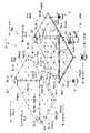
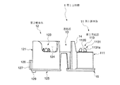
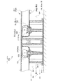
本発明に係る床パネルPは、図1、図2などに示すように、所定部位に形成した分画開口部によって分画された複数の単位パネルを有する平面視略正方形状のパネル本体PMと、隣接する単位パネルのコーナー部が集合する部位を支持する第1支持脚1と、パネル本体PMの四つの隅部をそれぞれ支持する第2支持脚2と、パネル本体PMの略中央部を支持する第3支持脚3とを備えたものである。そして、パネル本体PMを第1支持脚1、第2支持脚2、第3支持脚3に支持させた状態で、当該床パネルPを、例えば、建築床面FL(図14、図15参照。)に複数並べて敷設することにより、パネル本体PMと建築床面FLとの間にコード類を配線可能な二重床としての機能を発揮するようにしている。
The floor panel P according to the present invention includes a panel body PM having a substantially square shape in plan view and having a plurality of unit panels that are fractionated by a fractional opening formed in a predetermined portion, as shown in FIGS.
より具体的に各部を説明する。 Each part will be described more specifically.
パネル本体PMは、概略平板状の表材PM1と、この表材PM1の下面側に位置する裏材PM2とを重合させるとともに、これら表材PM1と裏材PM2とを後述する適宜の手段で一体的に連結したものとしている。 The panel main body PM polymerizes a substantially flat surface material PM1 and a backing material PM2 located on the lower surface side of the surface material PM1, and integrates the surface material PM1 and the backing material PM2 by appropriate means to be described later. Are consolidated.
さらに、この表材PM1と裏材PM2とについて説明すると、表材PM1は、薄板状のスチール素材を塑性変形加工することにより形成されたものであり、4つの辺に囲まれた平面視略正方形状をなす面板部PM1aと、この面板部PM1aの各辺から垂下して設けた側縁部PM1bとを備えている。面板部PM1aには、各辺の中点X1から面板部PM1aの中心部に向かって所定距離延びる第1表材スリットSL1aと、隣り合う第1表材スリットSL1aの内方端部(面板部PM1aの中心側に位置する端部)同士を結ぶ線に沿って延びる第2表材スリットSL1bとを形成するとともに、これら第1表材スリットSL1a及び第2表材スリットSL1bにより分画開口部たる表材分画開口部SL1を構成し、この表材分画開口部SL1によって一枚の表材PM1が複数の単位パネル(1つの第1表材単位パネルPM11及び4つの第2表材単位パネルPM12)に分画されるようにしている。具体的には、第1表材単位パネルPM11は、4つの第2表材スリットSL1bに囲まれ、面板部PM1aの中央部に位置する平面視略正方形状のものである。第2表材単位パネルPM12は、1つの第2表材スリットSL1b、この第2表材スリットSL1bの両端からそれぞれ延びる第1表材スリットSL1a及びこれら各第1表材スリットSL1aの外方端部(面板部PM1aの反中心側に位置する端部)から第2表材スリットSL1bに対向する表材PM1のコーナー部に向かって延びる2つの辺PM121によって囲まれ、表材PM1の隅部を構成するようにした平面視略五角形状のものである。なお、各第2表材スリットSL1bの略中間部位には、表材PM1の肉厚方向に貫通していない接続部たる表材接続部PM1Xを設け、この表材接続部PM1Xにより第1表材単位パネルPM11と第2表材単位パネルPM12とが一部において連続するようにしている。また、各側縁部PM1bの中央部には、前記第1表材スリットSL1aの外方端部から側縁部PM1bに下方に向かって延びる第3表材スリットSL1cを形成している。また、各第2表材単位パネルPM12には、後述する裏材PM2に設けた突部PM22Tを収容し得る収容部PM12Sを形成してある。これら突部PM22Tと収容部PM12Sとが、位置ずれ抑制手段としての機能を発揮する。
各収容部PM12Sは、本実施形態では、下方に窪ませてなる平面視円形状の有底のものとしているが、例えば、貫通させた無底のものなど、これに限られない。
Further, the front material PM1 and the back material PM2 will be described. The front material PM1 is formed by plastic deformation of a thin steel material, and is substantially square in plan view surrounded by four sides. A face plate portion PM1a having a shape and a side edge portion PM1b provided to hang from each side of the face plate portion PM1a are provided. The face plate portion PM1a includes a first surface material slit SL1a extending a predetermined distance from the center X1 of each side toward the center portion of the surface plate portion PM1a, and an inner end portion (face plate portion PM1a of the adjacent first surface material slit SL1a. And a second surface material slit SL1b extending along a line connecting them), and a surface that is a fractional opening by the first surface material slit SL1a and the second surface material slit SL1b. The material fraction opening SL1 is configured, and one surface material PM1 is composed of a plurality of unit panels (one first surface material unit panel PM11 and four second surface material unit panels PM12) by the surface material fraction opening SL1. ). Specifically, the first surface material unit panel PM11 is surrounded by four second surface material slits SL1b and has a substantially square shape in plan view located at the center of the face plate portion PM1a. The second surface material unit panel PM12 includes one second surface material slit SL1b, a first surface material slit SL1a extending from both ends of the second surface material slit SL1b, and outer ends of the first surface material slits SL1a. Surrounded by two sides PM121 extending toward the corner portion of the surface material PM1 facing the second surface material slit SL1b from the end portion located on the opposite side of the face plate portion PM1a, the corner portion of the surface material PM1 is configured. The plan view has a substantially pentagonal shape. In addition, the surface material connection part PM1X which is a connection part which has not penetrated in the thickness direction of the surface material PM1 is provided in a substantially intermediate portion of each second surface material slit SL1b, and the first surface material is formed by the surface material connection part PM1X. The unit panel PM11 and the second surface material unit panel PM12 are partially continuous. Further, a third surface material slit SL1c extending downward from the outer end portion of the first surface material slit SL1a to the side edge portion PM1b is formed at the center of each side edge portion PM1b. Each second front material unit panel PM12 is formed with a housing part PM12S capable of housing a protrusion PM22T provided on a back material PM2 described later. These protrusions PM22T and the housing part PM12S exhibit a function as a positional deviation suppression means.
In the present embodiment, each housing portion PM12S has a bottomed shape with a circular shape in plan view that is recessed downward, but is not limited to this, for example, a bottomless one that is penetrated.
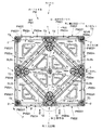
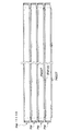
一方、裏材PM2は、薄板状のスチール素材を塑性変形加工することにより形成されたものであり、4つの辺によって囲まれた平面視略正方形状をなし、前記表材分画開口部SL1の投影位置に沿う位置に分画開口部たる裏材分画開口部SL2を形成している。具体的には、各辺の中点X2から裏材PM2の中心部に向かって所定距離延びる第1裏材スリットSL2aと、隣り合う第1裏材スリットSL2aの内方端部(裏材PM2の中心側に位置する端部)同士を結ぶ線に沿って延びる第2裏材スリットSL2bとを形成し、これら第1裏材スリットSL2a及び第2裏材スリットSL2bにより裏材分画開口部SL2を構成し、この裏材分画開口部SL2によって一枚の裏材PM2が複数の単位パネル(1つの第1裏材単位パネルPM21及び4つの第2裏材単位パネルPM22)に分画されるようにしている。具体的には、第1裏材単位パネルPM21は、4つの第2裏材スリットSL2bに囲まれ、裏材PM2の中央部に位置する平面視略正方形状のものである。第2裏材単位パネルPM22は、1つの第2裏材スリットSL2b、この第2裏材スリットSL2bの両端からそれぞれ延びる第1裏材スリットSL2a及びこれら各第1裏材スリットSL2aの外方端部(裏材PM2の反中心側に位置する端部)から第2裏材スリットSL2bに対向する裏材PM2のコーナー部に向かって延びる2つの辺PM221によって囲まれ、裏材PM2の4つの隅部にそれぞれ位置する平面視略五角形状のものである。なお、各第2裏材スリットSL2bの略中間部位に、裏材PM2の肉厚方向に貫通していない接続部たる裏材接続部PM2Xを設け、この裏材接続部PM2Xにより第1裏材単位パネルPM21と第2裏材単位パネルPM22とをそれぞれ一部において連続させている点も表材PM1と同様である。 On the other hand, the backing PM2 is formed by plastically deforming a thin steel material, has a substantially square shape in plan view surrounded by four sides, and is formed on the surface material partition opening SL1. A backing fraction opening SL2 that is a fraction opening is formed at a position along the projection position. Specifically, the first backing slit SL2a extending a predetermined distance from the middle point X2 of each side toward the center of the backing PM2, and the inner end portion of the adjacent first backing slit SL2a (of the backing PM2) A second backing slit SL2b extending along a line connecting the ends) located on the center side, and the backing fraction opening SL2 is formed by the first backing slit SL2a and the second backing slit SL2b. The single backing material PM2 is divided into a plurality of unit panels (one first backing material unit panel PM21 and four second backing material unit panels PM22) by the backing material separation opening SL2. I have to. Specifically, the first backing unit panel PM21 is surrounded by four second backing slits SL2b and has a substantially square shape in plan view located at the center of the backing PM2. The second backing unit panel PM22 includes one second backing slit SL2b, a first backing slit SL2a extending from both ends of the second backing slit SL2b, and an outer end portion of each of the first backing slit SL2a. The four corners of the backing PM2 are surrounded by two sides PM221 extending from (the end located on the opposite side of the backing PM2) to the corner of the backing PM2 facing the second backing slit SL2b. Are substantially pentagonal in plan view. A backing material connection part PM2X, which is a connection part that does not penetrate in the thickness direction of the backing material PM2, is provided at a substantially intermediate portion of each second backing material slit SL2b, and a first backing material unit is provided by this backing material connection part PM2X. The point that the panel PM21 and the second backing unit panel PM22 are partially continuous is also the same as the surface material PM1.
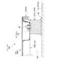
しかして、裏材PM2は、表材PM1と重合させた状態において、図2に示すように、表材PM1の下面側に密接する平板部PM2mと、裏材PM2の強度を確保すべく絞り加工により溝状に形成された補強部PM2nとを有し、部分的に凹凸形状をなすように形成されている。具体的には、平板部PM2mについては、第1裏材単位パネルPM21及び各第2裏材単位パネルPM22の各周縁部と、第1裏材単位パネルPM21及び各第2裏材単位パネルPM22の中央部位を平板部PM2mとしている。なお、その平板部PM2mのうち、各第2裏材単位パネルPM22の略中央部の平板部PM2mは、平面視略三角形状をなすものとし、また、第1裏材単位パネルPM21の略中央部に対向させるようにして設けた4つの平板部PM2mは、それぞれ平面視略三角形状をなすものとしている。一方、補強部PM2nについては、第1裏材単位パネルPM21及び各第2裏材単位パネルPM22の各周縁部位に沿った所定部位を、補強部PM2nとしてる。ここで、その所定部位とは、第1裏材単位パネルPM21の略中央部に対向させるようにして設けた4つの平板部PM2mに係るものについては、それぞれの平板部PM2mが、他の平板部PM2m及び第1裏材単位パネルPM21の周縁部に対して側面視略凹溝状に接続される部位としている。また、各第2裏材単位パネルPM22の略中央部の平板部PM2mに係るものについては、その平板部PM2mが、第2裏材単位パネルPM22の周縁部に対して側面視略凹溝状に接続される部位としている。 Thus, the backing material PM2 is drawn to ensure the strength of the backing material PM2 and the flat plate portion PM2m in close contact with the lower surface side of the backing material PM1, as shown in FIG. And a reinforcing portion PM2n formed in a groove shape, and is formed to have a partially uneven shape. Specifically, for the flat plate portion PM2m, the peripheral portions of the first backing unit panel PM21 and each second backing unit panel PM22, and the first backing unit panel PM21 and each second backing unit panel PM22. The central part is a flat plate portion PM2m. Of the flat plate portions PM2m, the flat plate portion PM2m at the substantially central portion of each second backing unit panel PM22 has a substantially triangular shape in plan view, and the substantially central portion of the first backing unit panel PM21. The four flat plate portions PM2m provided so as to face each other have a substantially triangular shape in plan view. On the other hand, for the reinforcing part PM2n, a predetermined part along each peripheral part of the first backing unit panel PM21 and each second backing unit panel PM22 is set as the reinforcing part PM2n. Here, with respect to the four portions of the flat plate portion PM2m provided so as to be opposed to the substantially central portion of the first backing unit panel PM21, the predetermined portion is the other flat plate portion. It is set as the site | part connected by the side view substantially concave groove shape with respect to the peripheral part of PM2m and 1st backing unit panel PM21. Moreover, about the thing which concerns on flat plate part PM2m of the approximate center part of each 2nd backing material unit panel PM22, the flat plate part PM2m is a side view substantially concave groove shape with respect to the peripheral part of 2nd backing material unit panel PM22. It is a connected part.
また、図1、図2に示すように、第1裏材単位パネルPM21の各コーナー部に後述する第1支持脚1の第1突起部113が取付可能な第1取付口T1を形成するとともに、第1裏材単位パネルPM21の中央に後述する第3支持脚3が取付可能な第4取付口T4を形成してある。一方、第2裏材単位パネルPM22の各コーナー部のうち、第1裏材単位パネルPM21及び他の第2裏材単位パネルPM22に隣接するコーナー部に後述する第1支持脚1の第2突起部123が取付可能な第2取付口T2を形成するとともに、第1裏材単位パネルPM21及び他の第2裏材単位パネルPM22に隣接しないコーナー部、すなわち裏材PM2の四隅の隅部に後述する第2支持脚2が取付可能な第3取付口T3を形成してある。これら第1取付口T1、第2取付口T2、第3取付口T3及び第4取付口T4(以下、取付口Tと総称する。)は、何れも補強部PM2nの前記面板部PM1aに対して平行な面に形成され、その面の肉厚方向に貫通している。第1取付口T1、第3取付口T3及び第4取付口T4は、平面視円形状をなし、第2取付口T2のみが、平面視長円形状をなすようにしている。なお、本実施形態では、第2取付口T2が、裏材PM2に設けた複数の第2裏材スリットSL2bのうち、当該第2取付口T2に最も近接している第2裏材スリットSL2b(換言すれば、第2表材スリットSL1b)の長手方向と直交する方向に、長手寸法を有するようにしている(図16参照。)。
As shown in FIGS. 1 and 2, a first attachment port T1 to which a
また、複数のパネル本体PMを積み重ねて収納などする際に、それら複数のパネル本体PMのスタッキング(図18参照。)を好適に行うために、第2裏材単位パネルPM22には、前記表材PM1の第2表材単位パネルPM12に形成した収容部PM12Sと対応する箇所に、その収容部PM12Sに収容され得る突部PM22Tを複数設けている(図1、図2参照。)。各突部PM22Tは、補強部PM2nよりもさらに下方に突出させたものであり、本実施形態においては、4つの第2裏材単位パネルPM22のうち、裏材PM2の対角線状線上に位置する一対の第2裏材単位パネルPM22にそれぞれ突部PM22Tを設けている(図2参照。)。 Further, when stacking and storing a plurality of panel main bodies PM, in order to suitably stack the plurality of panel main bodies PM (see FIG. 18), the second backing unit panel PM22 includes the surface material. A plurality of protrusions PM22T that can be accommodated in the accommodation part PM12S are provided at locations corresponding to the accommodation part PM12S formed in the second surface material unit panel PM12 of PM1 (see FIGS. 1 and 2). Each protrusion PM22T protrudes further downward than the reinforcing part PM2n. In the present embodiment, of the four second backing unit panels PM22, a pair positioned on the diagonal line of the backing PM2. Each of the second backing unit panels PM22 is provided with a protrusion PM22T (see FIG. 2).
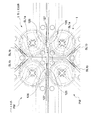
これら表材PM1の下面側と裏材PM2の上面側とを重合させて、複数箇所を適宜の手段(例えば、スポット溶接など)で連結することにより、表材PM1と裏材PM2とを一体的に組み付けてなる一のパネル本体PMが形成される。このパネル本体PMは、表材PM1と裏材PM2とを組み付けた状態において、第1表材単位パネルPM11と第1裏材単位パネルPM21とが重合するとともに、各第2表材単位パネルPM12と各第2裏材単位パネルPM22とが重合し、表材PM1及び裏材PM2それぞれに形成した表材分画開口部SL1及び裏材分画開口部SL2(以下、分画開口部SLと総称する。)を介して上述した重合関係にある第1表材単位パネルPM11と第1裏材単位パネルPM21とが第1単位パネルとして、また、各第2表材単位パネルPM12と各第2裏材単位パネルPM22とが第2単位パネルとして、おのおの同時に変形するように設定している。しかして、このパネル本体PMは、分画開口部SLを介して隣接する第1単位パネルと第2単位パネルとを相対変位させ得るように構成されている。そして、隣接する第1単位パネルと第2単位パネルと(以下、第1単位パネルと第2単位パネルとを「単位パネル」と総称する。)のコーナー部同士が集合する部位(以下、コーナー部集合部位とする。)に、後述する第1支持脚1を取り付けることができるようにしている。
By superposing the lower surface side of the front material PM1 and the upper surface side of the back material PM2 and connecting a plurality of locations by appropriate means (for example, spot welding), the front material PM1 and the back material PM2 are integrated. One panel main body PM assembled to is formed. In the panel body PM, in a state where the front material PM1 and the back material PM2 are assembled, the first front material unit panel PM11 and the first back material unit panel PM21 are superposed, and each second front material unit panel PM12 Each of the second backing unit panels PM22 is polymerized to form a front material fraction opening SL1 and a backing material fraction opening SL2 (hereinafter collectively referred to as a fraction opening SL) formed in the front material PM1 and the back material PM2, respectively. The first front panel unit panel PM11 and the first back panel unit panel PM21, which are in the above-described polymerization relationship via the above-described), serve as the first unit panel, and each second front panel unit panel PM12 and each second back panel. The unit panel PM22 is set as a second unit panel so as to be simultaneously deformed. Thus, the panel body PM is configured to be able to relatively displace the first unit panel and the second unit panel which are adjacent to each other through the fraction opening SL. And the part (henceforth a corner part) where the corner parts of the adjoining 1st unit panel and 2nd unit panel (henceforth a 1st unit panel and a 2nd unit panel are named generically "unit panel") gather. The
さらに、本実施形態では、裏材PM2に形成した第2取付口T2は、平面視長円形状を有しているため、この第2取付口T2に第1支持脚1の第2突起部123を取り付けた場合には、この第2突起部123は、裏材PM2に対して「遊びをもって取り付けられる状態」を有するようになる。すなわちこの取付状態において前記単位パネル同士の相対変位に伴って前記第2突起部123と第2取付口T2との相対位置が変化することにより、単位パネル同士(すなわち、第1単位パネルと第2単位パネル同士)の相対移動を許容する許容手段としての機能を発揮する。なお、本実施形態では、裏材PM2に形成した第1取付口T1と、第1支持脚1の第1突起部113とを取り付けた場合には、この第1突起部113が、裏材PM2に対して「遊びを生じることなく嵌合した状態」を有するように構成している。
Furthermore, in this embodiment, since the 2nd attachment port T2 formed in back material PM2 has a planar view ellipse shape, the
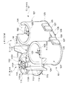
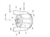
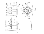
第1支持脚1は、図3、図4、図5、図6、図7、図8、図16等に示すように、コーナー部集合部位に隣接する各単位パネルの枚数に対応して設けた複数の脚本体と、これら脚本体同士を連結する連結部13とを備えたものである。具体的には、第1支持脚1は、例えば合成樹脂素材からなる一体成形品であり、コーナー部集合部位における第1裏材単位パネルPM21のコーナー部周辺を支持し得る第1脚本体11と、コーナー部集合部位において第1裏材単位パネルPM21に隣接する第2裏材単位パネルPM22のコーナー部周辺を支持し得る一対の第2脚本体12と、これら各脚本体を一体に連結する連結部13とを備えている。なお、本実施形態では、これら各脚本体11、12の中心部同士を結ぶ線分が第1脚本体11の中心部を頂点とする平面視略二等辺三角形状となるように各脚本体11、12を配置している(図4参照。)。またこのとき、一対の第2脚本体12を、当該床パネルPを平面視した際に、後述する位置決め手段がパネル本体PMから突出する位置に位置付けられるように、パネル本体PMの側縁部PM1bに沿って配置するようにしている。また、第1脚本体11および第2脚本体12の上端側を硬質樹脂とする一方、第1脚本体11および第2脚本体12の下端側(特に建築床面FLと接触する部位)及び連結部13を軟質樹脂とするとともに、これら各部を一体に射出成形によって形成する2色(異材質)成形方法を採用するようにしている。
As shown in FIGS. 3, 4, 5, 6, 7, 8, 8, and 16 etc., the
以下、各部についてより具体的に説明すると、第1脚本体11は、概略円筒状をなす第1周壁部111と、第1周壁部111の内周に平面視略十字状に設けられ第1周壁部111と略同じ高さ寸法を有する第1リブ112と、第1リブ112同士が交叉する部位に関連付けて設けられ第1周壁部111の上端より上方に突出させてなる突起部たる第1突起部113とを有する。この第1突起部113は、前記裏材PM2の第1裏材単位パネルPM21のコーナー部に形成した第1取付口T1に係合可能なものであり、第1突起部113の軸中心を中心として十字状をなすように形成したスリット113Sと、このスリット113Sを挟むように配置した弾性変形し得る4つの弾性部1131とを備えている。そして、各弾性部1131には、その先端部に鉤状の係合片1131aを一体に備えるようにしている。また、第1周壁部111と第1リブ112との間には、後述する高さ調節部材たる第1ライナーR1に設けた第1挿入部が挿入可能な概略円筒状をなす挿入穴たる第1挿入穴11Xを設けている。さらに、第1周壁部111の外周には、第2脚本体12側に向かって延出させてなる一対の鍔部114を設けている。そして、この鍔部114の上端が、第1周壁部111の上端及び突起部の上端よりもさらに上方に位置するように設定している。また、第1周壁部111の下端部における径が第1周壁部111の他の部位より若干大径となるように設定するとともに、この第1周壁部111の下端側に、建築床面FLに接地し得る円環状の第1接地部115を設けている。さらにまた、本実施形態では、この第1周壁部111の高さ寸法と、後述する第2支持脚2を構成する隅部支持用周壁部21の高さ寸法と、後述する第3支持脚3の中央支持用周壁部31の高さ寸法とを、略同一に構成している。
Hereinafter, each part will be described in more detail. The
一方、各第2脚本体12は、概略円筒状をなし前記第1脚本体11の第1周壁部111より大きい高さ寸法を有する第2周壁部121と、第2周壁部121の内周に平面視略十字状に設けられ前記第1周壁部111と略同じ高さ寸法を有する第2リブ122と、第2リブ122同士が交叉する部位に関連付けて設けられ第2リブ122の上端より上方に突出させてなる突起部たる第2突起部123とを有する。
On the other hand, each second leg
さらに詳述すると、第2周壁部121は、その上縁が前記第1脚本体11の鍔部114の上縁と略同じ高さ位置となるように設定されており、第2周壁部121の一部に第2リブ122の上縁と略同じ高さ位置まで切り欠いてなる切欠部124を形成してある。そして、各第2脚本体12をそれぞれ対応する第2裏材単位パネルPM22のコーナー部に取り付けた場合に、第2周壁部121の上縁が第2裏材単位パネルPM22の平板部PM2mに当接するとともに、切欠部124によって第2周壁部121の上縁と第2裏材単位パネルPM22の補強部PM2nとの干渉を回避し、切欠部124に第2裏材単位パネルPM22の補強部PM2nが位置するように設定している。
More specifically, the second
第2突起部123は、前記裏材PM2の第2裏材単位パネルPM22のコーナー部に形成した第2取付口T2に係合可能なものであり、前記第1脚本体11の第1突起部113と略同様の形状をなすものである。
The
加えて、本実施形態では、第2周壁部121の下端部に第2周壁部121の他の部位より若干大径となるように設定している。そして、この第2周壁部121の下端側に、建築床面FLに接地し得る第2接地部125を形成するとともに、第2周壁部121の外周に他方の第2脚本体12に向かって延出させてなる概略板状の延出部126を設けている。各延出部126は第2リブ122よりも小さい高さ寸法を有し、これら各延出部126に、前記第1脚本体11から離れる方向に概略板状の突出部127を設け、これら突出部127が各第2脚本体12の第2接地部125の外縁同士を結んた線分よりも前記第1脚本体11から離れる方向に突出するように設定している。そして、本実施形態においては、突出部127の正面視における巾寸法d1(延出部126の延出方向に沿った寸法)を、延出部126の正面視における巾寸法d2の略半分に設定し(図4参照。)、一方の第2脚本体12の延出部126には、突出部127を延出部126の基端部側に設け、他方の第2脚本体12の延出部126には、突出部127を延出部126の先端部に設けている。これにより、一対の第1支持脚1を第2脚本体12同士が当接するように対向配置した場合、対応する突出部127同士が延出方向に隣接し、第1支持脚1を、延出部126の延出方向へ相対移動することが禁止される。このように、各延出部126は、当該床パネルPの位置決めを行う位置決め手段(特に、隣接配置した床パネルP同士が所定位置よりさらに近接することを禁止する近接禁止手段)としての機能を発揮する。また、各突出部127は、当該床パネルPの位置決めを行う位置決め手段(特に、隣接配置した床パネルP同士が、それらのパネル本体PMの側縁部PM1b同士を略沿わせた状態で、所定位置よりさらに延出部126の延出方向に沿ってずれ動くことを禁止するずれ移動禁止手段)としての機能を発揮する。
In addition, in the present embodiment, the lower end portion of the second
また、一方の第2脚本体12の第2周壁部121に設定した前記第2接地部125に、他方の第2脚本体12に向かって延出する概略薄板状の舌片部128を一体に設けている。舌片部128の先端部における下面には、下方に向かって所定寸法突出させてなる突起129を設け(図3、図5、図8参照。)、図示はしていないが、この突起129を、下段側に位置付けたパネル本体PMの第1表材スリットSL1aに挿入して、複数の第1支持脚1をスタッキング可能に構成している。なお、舌片部128はある程度の柔軟性を有するものであり、第1支持脚1を建築床面FL等に接地させた場合、第1支持脚1の最下位に位置する突起129が他の部位より優先して接地するが、第1支持脚1自体の自重により突起129の突出寸法に対応して舌片部128の先端部が上方に浮き上がるように弾性変形可能に設定してある。
Further, a generally thin plate-
第2支持脚2は、図1に示すように、パネル本体PMのコーナー部であって且つ前記単位パネルが隣接しない部位において、前記建築床面FLに接地しながら前記パネル本体PMを支持するものである。なお、図示はしていないが、当該第2支持脚2と建築床面FLとの間に、床面の高さ調節をするための高さ調節部材たる第2ライナー(図示せず)を設け、当該第2支持脚2が建築床面FLに対して直接接しないようにしてもよい。
As shown in FIG. 1, the
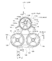
より具体的にこの第2支持脚2は、図9、図10、図11、図15などに示すように、概略円筒状をなす隅部支持用周壁部21と、隅部支持用周壁部21の内周に平面視略十字状に設けられ隅部支持用周壁部21と略同じ高さ寸法を有する隅部支持用リブ22と、隅部支持用リブ22同士が交叉する部位に関連付けて設けられ隅部支持用周壁部21の上端より上方に突出させてなる突起部たる隅部支持用突起部23と、前記隅部支持用周壁部21の外周に設けた4枚の隅部支持用羽根部24とを具備し、これら各部を合成樹脂により一体に形成した一体成形品である。
More specifically, as shown in FIGS. 9, 10, 11, and 15 and the like, the
さらに各部を詳述すると、隅部支持用周壁部21は、その上端部に、当該第2支持脚2を前記パネル本体PMに取り付けた状態において前記裏材PM2の前記補強部PM2nを支持し得る第1支持部21aを有している。また、隅部支持用周壁部21の下端部における径が隅部支持用周壁部21の他の部位より若干大径となるように設定するとともに、この隅部支持用周壁部21の下端側に、建築床面FLに接地し得る円環状の隅部支持用接地部25を設けている。
More specifically, each corner supporting
隅部支持用リブ22は、前記第1脚本体11の第1リブ112と略同様のものであるので説明を省略する。
The
隅部支持用突起部23は、第1裏材単位パネルPM21及び他の第2裏材単位パネルPM22に隣接しないコーナー部、すなわち裏材PM2の四隅の隅部に形成した第3取付口T3に係合可能なものであり、その構成は、前記第1脚本体11の第1突起部113と略同様であるので説明を省略する。
The
隅部支持用羽根部24は、隅部支持用周壁部21から外方に向かって延出する薄板状のものであって、その上端部に、当該第2支持脚2を前記パネル本体PMに取り付けた状態において前記裏材PM2の前記平板部PM2mを支持し得る第2支持部24aを有している。また、この隅部支持用羽根部24の上端が、隅部支持用周壁部21の上端及び突起部の上端よりもさらに上方に位置するように設定している。さらに、本実施形態では、4枚の隅部支持用羽根部24のうち2枚の隅部支持用羽根部24を平面視略直線状を成すとともに前記隅部支持用周壁部21を挟むように配置し、他の2枚の隅部支持用羽根部24を平面視略ハの字状に配置することにより、4枚の隅部支持用羽根部24に設けた第2支持部24aが、パネル本体PMの隅部にある裏材PM2の平板部PM2mを支持するように、換言すれば、この第2支持部24aが、前記第1支持部21aよりもさらにパネル本体PMの縁部に近い部位を支持するように構成している。
The corner
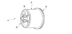
第3支持脚3は、図1に示すように、パネル本体PMの略中央部において、前記建築床面FLに接地しながら前記パネル本体PMを支持するものである。なお、図示はしていないが、当該第3支持脚3と建築床面FLとの間に、床面の高さ調節をするための高さ調節部材たる第3ライナー(図示せず)を設け、当該第3支持脚3が建築床面FLに対して直接接しないようにしてもよい。 As shown in FIG. 1, the third support leg 3 supports the panel body PM while being in contact with the building floor surface FL at a substantially central portion of the panel body PM. Although not shown, a third liner (not shown) as a height adjustment member for adjusting the height of the floor surface is provided between the third support leg 3 and the building floor surface FL. The third support leg 3 may not be in direct contact with the building floor surface FL.
より具体的にこの第3支持脚3は、図12、図13などに示すように、概略円筒状をなす中央支持用周壁部31と、中央支持用周壁部31の内周に平面視略十字状に設けられ中央支持用周壁部31と略同じ高さ寸法を有する中央支持用リブ32と、中央支持用リブ32同士が交叉する部位に関連付けて設けられ中央支持用周壁部31の上端より上方に突出させてなる突起部たる中央支持用突起部33とを具備し、これら各部を合成樹脂により一体に形成した一体成形品である。
More specifically, as shown in FIGS. 12 and 13, the third support leg 3 includes a central support
さらに各部を詳述すると、中央支持用周壁部31は、第2支持脚2の隅部支持用周壁部21と略同様のものであるので説明を省略する。なお、本実施形態では、この中央支持用周壁部31の下端側に、建築床面FLに接地し得る円環状の中央支持用接地部34を設けている。
Further, each part will be described in detail. The central support
中央支持用リブ32は、前記第1脚本体11の第1リブ112と略同様のものであるので説明を省略する。
The
中央支持用突起部33は、裏材PM2の第4取付口T4に係合可能なものであり、その構成は、前記第1脚本体11の第1突起部113と略同様であるので説明を省略する。
The
なお、本実施形態では、図8等に示すように、高さ調節部材たる第1上ライナーR11および高さ調節部材たる第1下ライナーR12(以下、第1ライナーR1と総称する。)を、層状に重合配置可能に構成することにより、当該床パネルPが、前記建築床面FLの不陸に対応し得るものとなるようにしている。 In the present embodiment, as shown in FIG. 8 and the like, the first upper liner R11 as a height adjusting member and the first lower liner R12 as a height adjusting member (hereinafter collectively referred to as a first liner R1) are used. The floor panel P is configured to be able to cope with the unevenness of the building floor surface FL by being configured so as to be superposed in layers.
具体的には、第1上ライナーR11を、単独で前記第1支持脚1の下面側に取り付ける態様(第1取付態様)と、前記第1上ライナーR11と第1下ライナーR12とを重ねた状態で前記第1支持脚1の下面側に取り付ける態様(第2取付態様)とを取り得るようにしており、建築床面FLの不陸に対して適宜対応し得るようにしている。
Specifically, a mode (first mounting mode) in which the first upper liner R11 is independently attached to the lower surface side of the
各部を詳述すると、第1上ライナーR11は、概略薄板状の上ライナー面板部R111と、この上ライナー面板部R111の周端を略直角に起立させた上ライナー起立壁R112とを備えてなる。より具体的に、上ライナー面板部R111は、前記第1支持脚1の下面側を略覆い得る平面視略三角形状をなすものである。また、この上ライナー面板部R111の略中央部で且つ当該第1上ライナーR11と前記第1支持脚1とを取り付けた際にその第1支持脚1の第1挿入穴11Xと対応する位置に、円筒状の第1挿入部R11Xを設けている。
More specifically, the first upper liner R11 includes a substantially thin plate-like upper liner surface plate portion R111, and an upper liner standing wall R112 in which the peripheral end of the upper liner surface plate portion R111 is erected at a substantially right angle. . More specifically, the upper liner face plate portion R111 has a substantially triangular shape in plan view that can substantially cover the lower surface side of the
第1下ライナーR12は、概略薄板状の下ライナー面板部R121と、この下ライナー面板部R121の周端を略直角に起立させた下ライナー起立壁122とを備えてなる。より具体的に、下ライナー面板部R121は、前記第上ライナー面板部R111に重合配置してその下面側を略覆い得る平面視略三角形状をなすものである。また、この下ライナー面板部R121の略中央部で且つ当該第1下ライナーR12と前記第1上ライナーR11とを十合配置した際にその第1上ライナーR11の第1挿入部R11Xに挿入される円筒状の第2挿入部R12Xを設けている。そして、第1上ライナーR11と第1下ライナーR12とを重合配置した際に、上ライナー起立壁R112が下ライナー起立壁122に呑み込まれるように、下ライナー面板部R121を上ライナー面板部R111よりも若干大きく構成している。
The first lower liner R12 includes a substantially thin plate-like lower liner surface plate portion R121, and a lower
以下、上述のように構成される床パネルPの使用方法について、(1)床パネルPの敷設方法、(2)敷設後の二重床としての使用方法、および(3)床パネルPの収納方法に分けて具体的に説明を行う。 Hereinafter, regarding the usage method of the floor panel P configured as described above, (1) the installation method of the floor panel P, (2) the usage method as a double floor after installation, and (3) the storage of the floor panel P Specific explanation will be given by dividing into methods.
(1)床パネルPの敷設方法について。 (1) About laying method of floor panel P.
まず、パネル本体PMの第1取付口T1に対して第1支持脚1の第1突起部113をそのパネル本体PMの下方から挿入するとともに、パネル本体PMの第2取付口T2に対して第1支持脚1の第2突起部123をそのパネル本体PMの下方から挿入することにより、パネル本体PMと第1支持脚1とを取り付ける。同様にして、パネル本体PMと第2支持脚2および第3支持脚3とを取り付けることにより、床パネルPを完成させる。このとき、パネル本体PMを、天地を逆にするなどして、第1支持脚1などを取り付けるようにしてもよい。このように、パネル本体PMに第1支持脚1等を予め取り付けておくことで、施工時間の短縮などを図ることができる。
First, the
そして、建築床面FLの適宜位置に、一の床パネルPを配置する。なお、床パネルPの第1支持脚1を建築床面FL等に接地させた場合、第1支持脚1の最下位に位置する突起129が他の部位より優先して接地するが、第1支持脚1自体の自重により突起129の突出寸法に対応して舌片部128の先端部が弾性変形して上方に浮き上がる(図示せず。)ので、この突起129が、床パネルPの配置の妨げとなることは無い。
And the one floor panel P is arrange | positioned in the appropriate position of the building floor surface FL. In addition, when the
次に、建築床面にFLに配置済みの一の床パネルPに対して、他の床パネルPを整列させて配置する。このとき、まず、両方の床パネルPの側縁部PM1b同士を沿わすように配置してから、側縁部PM1b同士を沿わすようにしながら他の床パネルPを移動して整列させても良いし、あるいは、両床パネルPをある程度整列させた状態においてから、他の床パネルPを一の床パネルPに近づけて整列させても良い。 Next, the other floor panel P is arranged and arranged with respect to the one floor panel P already arranged in the FL on the building floor. At this time, after arranging the side edge portions PM1b of both floor panels P along the side edge portions PM1b, other floor panels P may be moved and aligned along the side edge portions PM1b. Alternatively, after the two floor panels P are aligned to some extent, the other floor panels P may be aligned close to one floor panel P.
しかして、一の床パネルPと他の床パネルPとが整列する状態になると、双方に設けている位置決め手段同士が当接を行う。この状態で、一の床パネルPを他の床パネルPに対して、近接する向きに外力(図示せず)を加えても、一の床パネルPの位置決め手段と他の床パネルPの位置決め手段とが、当接するため(図17参照。)、双方の床パネルPは、その場に留まり続ける。したがって、双方のパネル本体PM同士も当接することが無く、パネル本体PM同士が当接することにより生じる金属音の発生は起こらない。また、両方の床パネルPの側縁部PM1b同士を沿わすようにしながら他の床パネルPを移動して整列させたその向きと同方向に外力(図示せず)を加えても、双方の床パネルPの突出部126同士が当接するため、双方の床パネルPは、その場に留まり続ける。
Thus, when one floor panel P and another floor panel P are aligned, the positioning means provided on both floors come into contact with each other. In this state, even if an external force (not shown) is applied in the direction in which one floor panel P is adjacent to the other floor panel P, the positioning means of one floor panel P and the positioning of the other floor panel P Both floor panels P remain in place because the means abut (see FIG. 17). Therefore, both panel main bodies PM are not in contact with each other, and no metal sound is generated when the panel main bodies PM are in contact with each other. Further, even if an external force (not shown) is applied in the same direction as the direction in which the other floor panels P are moved and aligned while keeping the side edges PM1b of both floor panels P along each other, Since the
このようにして、複数の床パネルPを建築床面FL上に整列させて適宜配置することができる。 In this way, a plurality of floor panels P can be arranged appropriately on the building floor FL.
なお、一般的な建築床面FLは、通常若干の不陸を有しているが、このような不陸を有する建築床面FLに対して床パネルPを配置した場合でも、効果的にその不陸を吸収することができる。 In addition, although a general building floor FL usually has a slight unevenness, even when the floor panel P is arranged on the building floor FL having such an unevenness, the floor is effectively Can absorb unevenness.
具体的には、裏材PM2に形成した第2取付口T2は、平面視長円形状を有しているため、図14に示すように、この第2取付口T2に第1支持脚1の第2突起部123を取り付けた場合には、この第2突起部123は、裏材PM2に対して「遊びをもって取り付けられる状態」を有するようになる。すなわちこの取付状態において前記単位パネル同士の相対変位に伴って前記第2突起部123と第2取付口T2との相対位置が変化することにより、単位パネル同士(すなわち、第1単位パネルと第2単位パネル同士)の相対移動を許容する許容手段としての機能を発揮する。したがって、一方の単位パネル側に凸状の不陸があると、その不陸に対応すべく第2取付口T2内を第2突起部123が移動して、すなわち、第2取付口T2と第2突起部123との取付位置が相対的に変化して、これにともない、単位パネル同士も相対変位する。また、このとき、連結部13も、単位パネルの変形に伴って変形し得るので、単位パネル同士の相対変位が円滑に行われる。このようにして、効果的に不陸を吸収することができる。
Specifically, since the second mounting port T2 formed in the backing PM2 has an oval shape in plan view, as shown in FIG. 14, the second mounting port T2 has the
(2)敷設後の二重床としての使用方法。 (2) Usage as a double floor after laying.
複数の床パネルPを建築床面FL上に敷設し、パネル本体PMと建築床面FLとの間の空間SP(図14、図15参照。)に、例えば、配線類(図示せず)を通せば、床パネルPの表面側にそれら配線類が露出することを効果的に防止できるので、オフィス空間内に配線類が無駄に露出しないといった非常に見栄えのよいオフィスレイアウトを行うことができる。 A plurality of floor panels P are laid on the building floor surface FL, and, for example, wiring (not shown) is provided in a space SP (see FIGS. 14 and 15) between the panel body PM and the building floor surface FL. If it is passed, it is possible to effectively prevent the wirings from being exposed on the surface side of the floor panel P. Therefore, it is possible to perform a very attractive office layout in which the wirings are not unnecessarily exposed in the office space.
このとき、図17に示すように、隣接する床パネルPの位置決め手段が、略常時当接する状態にあり、隣接するパネル本体PM同士が直接当接することはない。したがって、床パネルP上を歩行したとしても、パネル本体PM同士が当接することにより生じる金属音(ここでは、歩行音に類される。)の発生もない。 At this time, as shown in FIG. 17, the positioning means of the adjacent floor panel P is in a state of being in constant contact, and the adjacent panel bodies PM are not in direct contact with each other. Therefore, even if the user walks on the floor panel P, there is no generation of a metal sound (here, similar to a walking sound) that occurs when the panel main bodies PM come into contact with each other.
しかも、床パネルPMを金属製のものとしているため、床パネルP自体の剛性を効果的に確保でき、好適な歩行感を得られる。 Moreover, since the floor panel PM is made of metal, the rigidity of the floor panel P itself can be effectively secured, and a suitable walking feeling can be obtained.
さらに、建築床面FLが、異なる高さを有するものであったとしても、第1支持脚1等を樹脂製のものとしているので、然るべき高さ寸法を有するものに適宜交換して、そのようなものにも有効に対応することもできる。
Furthermore, even if the building floor surface FL has a different height, the
(3)床パネルPの収納方法。 (3) A method for storing the floor panel P.
まず、第1支持脚1をパネル本体PMから取り外す向きにその第1支持脚1に外力を加えると、第1支持脚1は第1突起部113によって、パネル本体PMの第1取付口T1に、その弾性変形を利用して取り付けているだけであるので、容易に第1支持脚1を、パネル本体PMから簡単に取り外すことができる。また、同様にして、第2支持脚2および第3支持脚3を、簡単にパネル本体PMから取り外すことができる。すなわち、床パネルPを、樹脂製のものと金属性のものとに容易に分解できる。
First, when an external force is applied to the
そして、面板部が上方を向くようにした一のパネル本体PMに対して、同様にした他のパネル本体PMを積み重ねる。すると、下段側のパネル本体PMの面板部に設けた収容部PM12Sに対して、上段側のパネル本体PMに設けた突部PM22Tが収納される。 And the other panel main body PM which carried out similarly is piled up with respect to one panel main body PM which made the faceplate part face upward. Then, the protrusion PM22T provided in the upper panel body PM is accommodated in the accommodation part PM12S provided in the face plate portion of the lower panel body PM.
しかして、複数のパネル本体PMを、図18に示すように、積み重ねた状態で、例えば水平方向に外力が加わったとしても、位置ずれ抑制手段としての機能を発揮する収容部PM12Sと突部PM22Tとによって、積み重ねている状態が崩れることを効果的に防止することができる。 Accordingly, as shown in FIG. 18, the housing parts PM12S and the protrusions PM22T exhibiting a function as positional deviation suppression means even when an external force is applied in the horizontal direction, for example, in a stacked state as shown in FIG. Thus, it is possible to effectively prevent the stacked state from collapsing.
なお、図示はしないが、パネル本体PMと第1支持脚1等とを分解しないで、すなわち、床パネルPを完成品のままで積み重ねても良い。
Although not shown, the panel body PM and the
この場合には、下段側のパネル本体PMの第1表材スリットSL1aに対して、上段側の第1支持脚1に設けた突起129が挿入される。しかして、複数の床パネルPを積み重ねた状態で、例えば水平方向に外力が加わったとしても、第1表材スリットSL1aと突起129とによって、積み重ねている状態が崩れることを効果的に防止することができる。
In this case, the
このように、本実施形態に係る床パネルPは、パネル本体PMと第1支持脚1等とを予め一体的に取り付けているため、従来のものと比較して施工現場における部品点数を削減することができ、それに伴って施工手順の簡素化、施工効率の向上を有効に図ることができる。しかも、第1支持脚1が隣接する単位パネルの各々と係り合うことでこれら単位パネル同士を連結するものであるため、運搬時や施工時に隣接する単位パネル同士が分離する虞がなく、取扱いの便を向上させるとともに、隣接する単位パネル同士の相対変位を許容する許容手段を設けていることにより、不陸に対応させて単位パネル同士を相対変位させることが可能となり、その結果、床パネルPとしての不陸にきめ細かく対応させてがたつきを効果的に抑えることができる。
As described above, the floor panel P according to the present embodiment has the panel body PM and the
前記各単位パネルが平面視略多角形状をなし、前記第1支持脚1が、前記単位パネルが隣接する部位のうち各単位パネルのコーナー部同士が集合する部位に取り付けられるようにしているため、第1支持脚1によって、隣接する単位パネルのコーナー部を支持することができ、がたつきをより効果的に抑制し、安定した支持状態を実現することができる。
Since each unit panel has a substantially polygonal shape in plan view, the
また、前記建築床面FLの不陸に対応して前記第1支持脚1と前記建築床面FLとの間に介在させ得る第1ライナーR1を、前記第1支持脚1の下面側に取付可能に構成しているため、この第1ライナーR1を第1支持脚1の下面側に取り付けることによって、不陸の調整を容易に行うことができる。
A first liner R1 that can be interposed between the
しかも、この第1ライナーR1が、概略薄板状のものであって且つ前記第1支持脚1の下面側を略覆い得る平面視形状をなすようにしているため、単位パネルが隣接する部位に前記分画開口部SLを跨ぐように取り付けられる第1支持脚1の下面において高さ違いが生じさることがなく、好適である。
In addition, since the first liner R1 has a substantially thin plate shape and has a shape in plan view that can substantially cover the lower surface side of the
さらに、複数の前記第1ライナーR1を、前記建築床面FLの不陸に対応させて層状に重合可能に設定しているので、あらゆる不陸に柔軟に対応できる。 Further, since the plurality of first liners R1 are set so as to be superposed in layers in correspondence with the unevenness of the building floor surface FL, it is possible to flexibly cope with any unevenness.
第1支持脚1が、隣接する前記各単位パネルに対応して設けた第1脚本体11及び対を成す第2脚本体12と、これら脚本体同士を連結する連結部13とを具備してなり、前記第1ライナーR1に上方に向けて突出させてなる第1挿入部R11Xを設けるとともに、第1脚本体11に前記第1挿入部R11Xが挿入可能な第1挿入穴11Xを形成し、この第1挿入穴11Xに第1挿入部R11Xを挿入することにより前記第1ライナーR1を前記第1支持脚1に取付可能に構成しているため、簡素な構造を採用して前記第1ライナーR1を第1支持脚1に取り付けることができる。
The
また、前記パネル本体PMが、所定部位に前記分画開口部SLを形成した概略平板状の表材PM1と、この表材PM1の裏面側に位置する裏材PM2とを重合させたものであり、この裏材PM2が、前記表材PM1に密接する平板部PM2mと、前記表材PM1の分画開口部SLに沿って平面視略凹溝状に形成された補強部PM2nとを有するようにしているため、表材PM1が裏材PM2に向かう方向に張り出す際に、表材PM1が裏材PM2に当接して変形が妨げられる不具合の発生を抑えることができるとともに、裏材PM2を凹凸形状とすることにより裏材PM2の強度、ひいてはパネル本体PMの強度を有効に高めることができる。 The panel body PM is obtained by polymerizing a substantially flat plate-like surface material PM1 in which the fraction opening SL is formed at a predetermined portion and a back material PM2 located on the back surface side of the surface material PM1. The backing material PM2 has a flat plate portion PM2m that is in close contact with the surface material PM1, and a reinforcing portion PM2n that is formed in a substantially concave groove shape in plan view along the fractional opening SL of the surface material PM1. Therefore, when the front material PM1 projects in the direction toward the back material PM2, it is possible to suppress the occurrence of a problem in which the front material PM1 abuts on the back material PM2 and prevents deformation, and the back material PM2 is uneven. By adopting the shape, the strength of the backing PM2, and consequently the strength of the panel body PM, can be effectively increased.
加えて、前記裏材PM2の前記分画開口部SLを、前記表材PM1の前記分画開口部SLの投影位置に沿う位置に形成しているため、表材PM1及び裏材PM2がそれぞれ形成した分画開口部SLに沿って同時に隣接する単位パネル同士を相対変位させることができ、建築床面FLの大きな不陸にも対応しやすくなる。 In addition, since the fraction opening portion SL of the backing material PM2 is formed at a position along the projection position of the fraction opening portion SL of the front material PM1, the front material PM1 and the backing material PM2 are respectively formed. The unit panels adjacent to each other along the fractional opening SL can be displaced relative to each other at the same time, and it becomes easy to cope with unevenness of the building floor FL.
さらに、前記第1支持脚1が、隣接する前記各単位パネルをそれぞれ支持する複数の脚本体11、12と、これら脚本体同士を連結する連結部13とを具備してなり、前記脚本体11、12に、前記第1支持脚1を前記パネル本体PMに取り付けた状態において、前記裏材PM2の前記補強部PM2nを支持する第1支持部21aと、前記裏材PM2の前記平板部PM2mを支持し得る第2支持部24aとを設けているため、パネル本体PMの強度を高めるために裏材PM2を凹凸形状とした場合であっても、第1支持脚1によって、裏材PM2の補強部PM2n及び平板部PM2mを支持することができ、安定した支持状態を実現することができる。
Further, the
また、第2取付口T2と第2突起部123とが許容手段としての機能を発揮するため、一方の単位パネル側に凸状の不陸があっても効果的に不陸を吸収することができる。このとき、連結部13も、単位パネルの変形に伴って変形し得るので、単位パネル同士の相対変位が円滑に行われる。
In addition, since the second mounting port T2 and the
前記各単位パネルが平面視略多角形状をなし、前記第1支持脚1の前記第2支持部24aが、前記各単位パネルのコーナー部において前記第1支持脚1の前記第1支持部21aよりもさらに前記単位パネルの縁部に近い部位を支持するようにしているため、第2支持部24aによって各単位パネルのできるだけ縁部を支持することができ、単位パネルの縁部で生じ易い浮き上がりを抑制することができる。
Each unit panel has a substantially polygonal shape in plan view, and the
また、前記パネル本体PMに、このパネル本体PMを複数平積みした状態において各パネル本体PMの水平方向への位置ずれを抑制する位置ずれ抑制手段を設けているため、パネル本体PMを好適にスタッキングすることができる。 Further, since the panel main body PM is provided with a positional deviation suppressing means for suppressing a positional deviation in the horizontal direction of each panel main body PM in a state where a plurality of the panel main bodies PM are stacked, the panel main body PM is suitably stacked. can do.
なお、本発明は、以上に詳述した実施形態に限られるものではない。 The present invention is not limited to the embodiment described in detail above.
例えば、前記パネル本体PMを平面視略多角形状をなすようにし、このパネル本体PMのコーナー部であって且つ前記単位パネルが隣接しない部位に、前記パネル本体PMを支持し且つ前記建築床面FLに接地し得る第2支持脚2を取り付けれるようにしてもよい。このようにすれば、パネル本体PMのより安定した支持状態を実現することができる。
For example, the panel main body PM has a substantially polygonal shape in plan view, and the panel main body PM is supported at a corner portion of the panel main body PM and the unit panel is not adjacent to the panel main body PM. A
また、表材PM1及び裏材PM2を、それぞれ薄板状のスチール素材を塑性変形加工することにより形成しているが、例えば、アルミダイキャスト製のものとする等、その形成方法は本実施形態に限られるものではない。 Further, the front material PM1 and the back material PM2 are formed by plastic deformation processing of a thin steel material, respectively. For example, the formation method is made of aluminum die cast, etc. It is not limited.
また、第1挿入穴11Xを、第1脚本体11に設けているが、第2脚本体2に設けるようにしてもよい。
Further, although the
また、一部の取付口と突起部とを嵌合した状態で取り付けるようにしてもよい。 Moreover, you may make it attach in the state which fitted some attachment openings and protrusions.
なお、本実施形態では、別体をなす第1脚本体11、第2脚本体12に、複数の突起部(第1突起部113、第2突起部123)を設けるようにしているが、第1脚本体11および第2脚本体を一体のものとして形成し、これに複数の突起部を設けるようにしてもよい。
In the present embodiment, the
また、連結部13を軟質樹脂で形成するようにしているが、この連結部13を硬質樹脂にて形成するようにしてもよい。
Moreover, although the
また、前記第1支持脚の連結部13を例えば変形可能に構成し、この連結部13が、突起部と取付口とによって実現している単位パネル同士の相対変位を許容する許容手段としての機能を発揮するように構成してもよい。この場合、連結部13を軟質樹脂により形成すると好適である。
Further, the connecting
その他、各部の具体的構成についても上記実施形態に限られるものではなく、本発明の趣旨を逸脱しない範囲で種々変形が可能である。 In addition, the specific configuration of each part is not limited to the above embodiment, and various modifications can be made without departing from the spirit of the present invention.
1・・・・・・第1支持脚
2・・・・・・第2支持脚
11・・・・・脚本体(第1脚本体)
11X・・・・挿入穴(第1挿入穴)
12・・・・・脚本体(第2脚本体)
13・・・・・連結部
21a・・・・第1支持部
24a・・・・第2支持部
113・・・・突起部(第1突起部)
123・・・・突起部(第2突起部)
FL・・・・・建築床面
P・・・・・・床パネル
PM・・・・・パネル本体
PM1・・・・表材
PM11・・・単位パネル(第1表材単位パネル)
PM12・・・単位パネル(第2表材単位パネル)
PM12S・・収容部
PM2・・・・裏材
PM2m・・・平板部
PM2n・・・補強部
PM21・・・単位パネル(第1裏材単位パネル)
PM22・・・単位パネル(第2裏材単位パネル)
PM22T・・突部
R1・・・・・高さ調節部材(第1ライナー)
R11・・・・高さ調節部材(第1上ライナー)
R12・・・・高さ調節部材(第1下ライナー)
R11X・・・挿入部(第1挿入部)
R12X・・・挿入部(第2挿入部)
R2・・・・・高さ調節部材(第2ライナー)
SL・・・・・分画開口部
SL1・・・・表材分画開口部
SL2・・・・裏材分画開口部
T・・・・・・取付口
T1・・・・・第1取付口
T2・・・・・第2取付口
T3・・・・・第3取付口
T4・・・・・第4取付口
1 ······
11X ··· Insertion hole (first insertion hole)
12 ... Leg body (2nd leg body)
13 ··· Connecting
123... Projection (second projection)
FL: Architectural floor surface P ... Floor panel PM ... Panel body PM1 ... Surface material PM11 ... Unit panel (first surface material unit panel)
PM12 ... Unit panel (second surface unit panel)
PM12S ··· Housing part PM2 ··· Backing material PM2m ··· Flat plate portion PM2n · · · Reinforcement portion PM21 ··· Unit panel (first backing material unit panel)
PM22 ... Unit panel (second backing unit panel)
PM22T ··· Projection R1 ··· Height adjustment member (first liner)
R11 ... Height adjustment member (first upper liner)
R12 ... Height adjustment member (first lower liner)
R11X ... insertion part (first insertion part)
R12X ... insertion part (second insertion part)
R2 ... Height adjustment member (second liner)
SL: Fraction opening SL1 ... Front material fraction opening SL2 ... Back material fraction opening T ... Mounting port T1 ... First mounting Port T2 ... Second mounting port T3 ... Third mounting port T4 ... Fourth mounting port
Claims (19)
所定部位に形成した分画開口部によって分画された複数の単位パネルを有するパネル本体と、当該パネル本体を支持し且つ前記建築床面に接地し得る第1支持脚とを具備してなり、
前記パネル本体が、前記分画開口部を介して隣接する前記単位パネル同士を相対変位させ得るものであり、
前記第1支持脚が、前記分画開口部を挟んで少なくとも2以上の前記単位パネルが隣接する部位に前記分画開口部を跨ぐように取り付けられ且つこれら隣接する単位パネルの各々と係り合うことでこれら単位パネル同士を連結するものであり、
前記単位パネルと前記第1支持脚との間に、前記単位パネル同士の相対変位を許容する許容手段を設けていることを特徴とする床パネル。 A floor panel laid on a building floor to form a double floor,
A panel main body having a plurality of unit panels fractionated by a fraction opening formed in a predetermined portion; and a first support leg that supports the panel main body and can be grounded to the building floor surface,
The panel body is capable of relatively displacing the unit panels adjacent to each other through the fraction opening,
The first support leg is attached so as to straddle the fraction opening at a portion where at least two or more unit panels are adjacent to each other with the fraction opening interposed therebetween, and is engaged with each of the adjacent unit panels. In order to connect these unit panels,
The floor panel characterized by providing the permissible means which accept | permits the relative displacement of the said unit panels between the said unit panel and the said 1st support leg.
所定部位に形成した分画開口部によって分画された複数の単位パネルを有するパネル本体と、当該パネル本体を支持し且つ前記建築床面に接地し得る第1支持脚とを具備してなり、
前記パネル本体が、前記分画開口部を介して隣接する前記単位パネル同士を相対変位させ得るものであり、
前記第1支持脚が、前記分画開口部を挟んで少なくとも2以上の前記単位パネルが隣接する部位に前記分画開口部を跨ぐように取り付けられ且つこれら隣接する単位パネルの各々と係り合うことでこれら単位パネル同士を連結するものであり、
前記第1支持脚に、前記単位パネル同士の相対変位を許容する許容手段を設けていることを特徴とする床パネル。 A floor panel laid on a building floor to form a double floor,
A panel main body having a plurality of unit panels fractionated by a fraction opening formed in a predetermined portion; and a first support leg that supports the panel main body and can be grounded to the building floor surface,
The panel body is capable of relatively displacing the unit panels adjacent to each other through the fraction opening,
The first support leg is attached so as to straddle the fraction opening at a portion where at least two or more unit panels are adjacent to each other with the fraction opening interposed therebetween, and is engaged with each of the adjacent unit panels. In order to connect these unit panels,
The floor panel according to claim 1, wherein the first support leg is provided with an allowance means for allowing relative displacement between the unit panels.
前記許容手段が、隣接する前記各単位パネル又は前記第1支持脚の何れか一方に形成した取付口に、他方に設けた突起部を遊びのない状態で取り付け、この取付状態において前記単位パネルの変形に伴って前記連結部が変形することにより前記単位パネル同士の相対変位を許容するように構成したものである請求項4記載の床パネル。 The first support leg comprises a plurality of leg bodies provided corresponding to the adjacent unit panels, and a connecting part for flexibly connecting the leg bodies,
The permissive means attaches a projection provided on the other to each of the adjacent unit panels or the first support legs in a state where there is no play. The floor panel according to claim 4, wherein the connecting portion is deformed along with the deformation to allow relative displacement between the unit panels.
Priority Applications (1)
| Application Number | Priority Date | Filing Date | Title |
|---|---|---|---|
| JP2004108576A JP2005290875A (en) | 2004-03-31 | 2004-03-31 | Floor panel |
Applications Claiming Priority (1)
| Application Number | Priority Date | Filing Date | Title |
|---|---|---|---|
| JP2004108576A JP2005290875A (en) | 2004-03-31 | 2004-03-31 | Floor panel |
Publications (1)
| Publication Number | Publication Date |
|---|---|
| JP2005290875A true JP2005290875A (en) | 2005-10-20 |
Family
ID=35324119
Family Applications (1)
| Application Number | Title | Priority Date | Filing Date |
|---|---|---|---|
| JP2004108576A Pending JP2005290875A (en) | 2004-03-31 | 2004-03-31 | Floor panel |
Country Status (1)
| Country | Link |
|---|---|
| JP (1) | JP2005290875A (en) |
Cited By (1)
| Publication number | Priority date | Publication date | Assignee | Title |
|---|---|---|---|---|
| DE102009001866A1 (en) | 2008-03-26 | 2009-10-01 | Denso Corporation, Kariya-City | Fuel supply pipe device and fuel injection device having the same |
-
2004
- 2004-03-31 JP JP2004108576A patent/JP2005290875A/en active Pending
Cited By (1)
| Publication number | Priority date | Publication date | Assignee | Title |
|---|---|---|---|---|
| DE102009001866A1 (en) | 2008-03-26 | 2009-10-01 | Denso Corporation, Kariya-City | Fuel supply pipe device and fuel injection device having the same |
Similar Documents
| Publication | Publication Date | Title |
|---|---|---|
| RU2537284C2 (en) | Plastic pallet | |
| AU2010305511A1 (en) | Drainage body | |
| JP2014150098A5 (en) | ||
| JP6319422B2 (en) | panel | |
| JP2011074823A (en) | Oil pan structure | |
| JP2013183466A (en) | Insulator for stator | |
| JP2005290875A (en) | Floor panel | |
| JP2005290874A (en) | Floor panel | |
| JP7378726B2 (en) | container | |
| JP2020051024A (en) | Floor panel reinforcement member | |
| JP4465131B2 (en) | Double floor structure | |
| JP4271191B2 (en) | Double floor structure | |
| JP5230747B2 (en) | Synthetic deck system | |
| JP6890809B2 (en) | tray | |
| JP7107542B2 (en) | Washroom floor structure | |
| JP7353118B2 (en) | floor panel material | |
| JP2018039531A (en) | tray | |
| JP5013592B2 (en) | Floor panel support structure | |
| JP7385218B2 (en) | corn | |
| JP6197252B2 (en) | Floor panel material | |
| JP2014190104A (en) | Floor panel material | |
| JP3589097B2 (en) | Floor bread structure | |
| JP2006160283A (en) | Stackable and nestable containers | |
| JP2005290861A (en) | Fitment stacking structure and stackable fitment | |
| JP4431515B2 (en) | Assembled shelf |