JP2005290874A - Floor panel - Google Patents
Floor panel Download PDFInfo
- Publication number
- JP2005290874A JP2005290874A JP2004108525A JP2004108525A JP2005290874A JP 2005290874 A JP2005290874 A JP 2005290874A JP 2004108525 A JP2004108525 A JP 2004108525A JP 2004108525 A JP2004108525 A JP 2004108525A JP 2005290874 A JP2005290874 A JP 2005290874A
- Authority
- JP
- Japan
- Prior art keywords
- panel
- floor
- floor panel
- leg
- support
- Prior art date
- Legal status (The legal status is an assumption and is not a legal conclusion. Google has not performed a legal analysis and makes no representation as to the accuracy of the status listed.)
- Pending
Links
- 229920005989 resin Polymers 0.000 claims abstract description 18
- 239000011347 resin Substances 0.000 claims abstract description 18
- 229910052751 metal Inorganic materials 0.000 claims abstract description 11
- 239000002184 metal Substances 0.000 claims abstract description 11
- 239000000463 material Substances 0.000 claims description 98
- 229910000831 Steel Inorganic materials 0.000 claims description 8
- 239000010959 steel Substances 0.000 claims description 8
- 238000006073 displacement reaction Methods 0.000 claims description 7
- 230000007613 environmental effect Effects 0.000 abstract description 5
- 230000000694 effects Effects 0.000 abstract description 3
- 230000002093 peripheral effect Effects 0.000 description 43
- 238000003780 insertion Methods 0.000 description 9
- 230000037431 insertion Effects 0.000 description 9
- 230000003014 reinforcing effect Effects 0.000 description 8
- 238000000034 method Methods 0.000 description 7
- 230000002159 abnormal effect Effects 0.000 description 4
- 238000010276 construction Methods 0.000 description 4
- 230000004308 accommodation Effects 0.000 description 3
- 238000009434 installation Methods 0.000 description 3
- 229920003002 synthetic resin Polymers 0.000 description 3
- 239000000057 synthetic resin Substances 0.000 description 3
- 230000000630 rising effect Effects 0.000 description 2
- 230000001629 suppression Effects 0.000 description 2
- 210000005182 tip of the tongue Anatomy 0.000 description 2
- 241000135309 Processus Species 0.000 description 1
- 229910052782 aluminium Inorganic materials 0.000 description 1
- XAGFODPZIPBFFR-UHFFFAOYSA-N aluminium Chemical compound [Al] XAGFODPZIPBFFR-UHFFFAOYSA-N 0.000 description 1
- 230000002542 deteriorative effect Effects 0.000 description 1
- 230000005489 elastic deformation Effects 0.000 description 1
- 230000001747 exhibiting effect Effects 0.000 description 1
- 238000009408 flooring Methods 0.000 description 1
- 238000001746 injection moulding Methods 0.000 description 1
- 238000004519 manufacturing process Methods 0.000 description 1
- 150000002739 metals Chemical class 0.000 description 1
- 238000012986 modification Methods 0.000 description 1
- 230000004048 modification Effects 0.000 description 1
- 238000000465 moulding Methods 0.000 description 1
- 238000005192 partition Methods 0.000 description 1
- 238000006116 polymerization reaction Methods 0.000 description 1
- 238000004064 recycling Methods 0.000 description 1
- 238000000926 separation method Methods 0.000 description 1
- 238000003860 storage Methods 0.000 description 1
- 230000009466 transformation Effects 0.000 description 1
- 238000003466 welding Methods 0.000 description 1
Images


Landscapes
- Floor Finish (AREA)
Abstract
Description
本発明は、建築床面上に敷設され二重床を構成する床パネルに関するものである。 The present invention relates to a floor panel that is laid on a building floor and constitutes a double floor.
近年の情報化社会に対応すべくオフィスのフロアは、電源コードやLANケーブル等の配線によってオフィスレイアウトの見栄えが悪くならないようにするために、2重床構造を有するようにとしたものが多くなってきている。 In order to cope with the information-oriented society in recent years, many office floors have a double floor structure in order to prevent the appearance of the office layout from deteriorating due to wiring such as power cords and LAN cables. It is coming.
このような2重床構造を実現するものとしては、樹脂製の床パネルを建築床面上に直接置敷きするようにした置敷タイプと呼称されるもの(例えば、特許文献1、2参照。)や、パネル本体とこのパネル本体を支持する支持脚とからなる床パネルを建築床面上に置敷くようにした施工タイプと呼称されるものが、一般的に知られている。
しかしながら、置敷タイプの床パネルは、樹脂の使用率が高くリサイクルに向いてはいるものの、例えば、難燃性を付与するためには高価な樹脂材料を用いなければならないといった問題を有している。 However, the floor panel of the flooring type has a problem that an expensive resin material has to be used in order to impart flame retardancy, for example, although the resin usage rate is high and suitable for recycling. .
一方、施工タイプの床パネルは、置敷タイプのものと比べて配線スペースや強度を確保できるものの、施工性に劣るといった問題点を有している。 On the other hand, the construction type floor panel has a problem that it is inferior in workability, although the wiring space and strength can be ensured as compared with the installation type floor panel.
本発明は、このような課題に着目してなされたものであって、主たる目的は、オフィスレイアウトを見栄えよく行えるとともに、生産性や施工性等にも優れ、且つ、環境問題にも効果的に対応可能であるといった、高機能な床パネルを提供することにある。 The present invention has been made paying attention to such problems, and its main purpose is to make the office layout look good, and to be excellent in productivity, workability, etc., and also effective in environmental problems. The object is to provide a highly functional floor panel that can be used.
すなわち、本発明の床パネルは、二重床を構成すべく、建築床面から離間した位置に配置されるパネル本体と、前記パネル本体を着脱可能に支持し且つ前記建築床面に接地し得る支持脚とを具備してなり、前記パネル本体を前記支持脚に支持させた状態で複数配置して使用するタイプの床パネルであって、前記パネル本体を金属製のものとする一方、前記支持脚を樹脂製のものとし、前記パネル本体に前記支持脚を予め取り付けた状態で、前記建築床面に対して敷設するように構成していることを特徴とする。 That is, the floor panel of the present invention can form a double floor, a panel main body disposed at a position spaced from the building floor, and can removably support the panel main body and be grounded to the building floor. A floor panel of a type comprising a plurality of support legs, wherein the panel main body is made of metal and is used in a state where the panel main body is supported by the support legs. The leg is made of resin, and is constructed so as to be laid on the building floor surface in a state where the support leg is attached in advance to the panel body.
このようなものであれば、金属製のパネル本体とこのパネル本体を着脱可能に支持する樹脂製の支持脚とにより二重床を成すように床パネルを構成し、且つ、パネル本体に支持脚を予め取り付けているため、近時の情報化社会に対応しつつもコンピュータ配線等によりオフィスレイアウトが乱雑になることを有効に防止でき、且つ、特にパネル本体によって剛性の高い床パネルを実現できる上に、当該床パネルの製造・組立および施工・解体も容易にでき、さらには、支持脚を取り替えるだけで、異なる高さの二重床にも対応することができ、加えて、パネル本体と支持脚とを分別廃棄できるので、地球環境にも優しいといった、床パネルを実現できる。すなわち、オフィスレイアウトを見栄えよく行えるとともに、生産性や特に施工性にも優れ、且つ、環境問題にも効果的に対応可能であるといった、高機能な床パネルを提供することができる。 If this is the case, the floor panel is configured to form a double floor with a metal panel body and a resin support leg that detachably supports the panel body, and the panel body has a support leg. Since it is attached in advance, it can effectively prevent the office layout from becoming messy due to computer wiring, etc. while responding to the recent information society, and in particular, the panel body can realize a highly rigid floor panel. In addition, the floor panel can be easily manufactured, assembled, installed, and disassembled. Furthermore, by replacing the support legs, it is possible to handle double floors of different heights. Since the legs can be separated and disposed, a floor panel that is friendly to the global environment can be realized. That is, it is possible to provide a high-functional floor panel that can perform an attractive office layout, is excellent in productivity and particularly workability, and can effectively cope with environmental problems.
なお、前記支持脚が、前記パネル本体を支持する複数の脚本体とこれら脚本体同士を連結する連結部とを具備するものであれば、複数の脚本体によって、パネル本体を安定支持する機能を確保しつつも、且つ、例えば、連結部材を建築床面やパネル本体から離間させたものととすれば、二重床部分を有効に活用することができる。 In addition, if the support leg includes a plurality of leg bodies that support the panel body and a connecting portion that connects the leg bodies, the function of stably supporting the panel body by the plurality of leg bodies is provided. For example, if the connecting member is separated from the building floor or the panel main body, the double floor portion can be effectively used while ensuring.
また、前記支持脚が、当該床パネルを平面視した際に、少なくとも一部が前記パネル本体の側縁より外方に突出する位置決め手段を備えるものであって、一の床パネルに対して他の床パネルを隣接配置する際に、一の床パネルの位置決め手段に対して、他の床パネルの位置決め手段を当接させて他の床パネルの位置決めを行い得るように構成しているものであれば、隣接する位置にある一の位置決め手段と他の位置決め手段とをそれぞれ当接させるだけで、一の床パネルの配置位置に対する他の床パネルの配置位置を決定できるため、床パネルのレイアウト作業を簡単に行うことができる。また、位置決め手段は、樹脂製であるため、例えば、複数並べた状態で床パネルを使用している際に、位置決め手段同士が擦れあっても、床パネル同士が擦れ合うことがないので、金属同士が擦れあったときに発生するような異音が発生せず、好適に使用できる。 In addition, the support leg includes positioning means that protrudes outward from the side edge of the panel body when the floor panel is viewed in plan, When the floor panels of one floor panel are arranged adjacent to each other, the positioning means of the other floor panel is brought into contact with the positioning means of one floor panel so that the positioning of the other floor panel can be performed. If there is, it is possible to determine the layout position of the other floor panel with respect to the layout position of the one floor panel simply by bringing the positioning means and the other positioning means in the adjacent positions into contact with each other. Work can be done easily. Further, since the positioning means is made of resin, for example, when the floor panels are used in a state where a plurality of the positioning panels are arranged, even if the positioning means rub against each other, the floor panels do not rub against each other. An abnormal noise that occurs when rubbing is generated does not occur, and can be suitably used.
また、前記支持脚が、複数の脚本体を備えるものであって、複数の脚本体のうち2つの脚本体を、前記パネル本体の側縁部に沿って並べて配置するとともに、その側縁部に沿って並べて配置した脚本体に、前記位置決め手段を設けているものであれば、複数の脚本体にそれぞれ設けた位置決め手段同士を当接させて、一の床パネルと他の床パネルとの間に形成される隙間を、より安定して確保することができるため、前記異音の発生を確実に防止することができる。 The support leg includes a plurality of leg bodies, and two leg bodies out of the plurality of leg bodies are arranged side by side along the side edge of the panel body, and the side edges thereof are arranged. If the positioning means is provided on the leg main body arranged side by side, the positioning means provided on each of the plurality of leg main bodies are brought into contact with each other, so that the one floor panel and the other floor panel are in contact with each other. Since the gap formed in the above can be more stably secured, the generation of the abnormal noise can be reliably prevented.
床パネル同士を近接させて配置する際の位置決めを行い易いようにするためには、前記位置決め手段が、隣接配置した床パネル同士が所定位置よりさらに近接することを禁止する近接禁止手段としての機能を有することが望ましい。 In order to facilitate positioning when floor panels are placed close to each other, the positioning means functions as a proximity prohibiting means for prohibiting adjacent floor panels from being closer to each other than a predetermined position. It is desirable to have
また、側縁部に沿って並べて配置している複数の脚本体において、一の脚本体が、前記パネル本体の側縁部と平行を成すべく隣接する他の脚本体に向かって延出させてなり且つ前記近接禁止手段を構成する延出部を備えるものであって、一の床パネルに設けた延出部と他の床パネルに設けた延出部とを当接させることにより、隣接する床パネル同士が所定位置よりさらに近接することを禁止しているようにしたものであれば、例えば、延出部のパネル本体の側縁部に沿って延びる寸法を大きく設定すれば、延出部同士の当接部分が増えるので、床パネルを隣接配置する際に、その位置決め作業を行いやすい。 Further, in the plurality of leg bodies arranged side by side along the side edge portion, one leg body extends toward another leg body adjacent to be parallel to the side edge portion of the panel body. And having an extension part constituting the proximity prohibiting means, and adjacent to each other by bringing an extension part provided on one floor panel into contact with an extension part provided on another floor panel. If the floor panels are prohibited from being closer to each other than a predetermined position, for example, if the dimension extending along the side edge of the panel body of the extension part is set large, the extension part Since the contact portions between each other increase, it is easy to perform the positioning work when arranging the floor panels adjacent to each other.
一の床パネルに対して他の床パネルを配置する際に、所定方向における位置決めを好適に行えるうえ、床パネル同士を所定方向に沿ってずれ動くことを効果的に禁止できるようにするためには、前記位置決め手段が、隣接配置した床パネル同士が、それらのパネル本体の側縁部同士を略沿わせた状態で、所定位置よりさらに所定方向に沿ってずれ動くことを禁止するずれ移動禁止手段としての機能を有することが望ましい。 When arranging other floor panels with respect to one floor panel, positioning in a predetermined direction can be favorably performed, and the floor panels can be effectively prohibited from moving in a predetermined direction. Is a displacement movement prohibition in which the positioning means prohibits the adjacently arranged floor panels from moving in a predetermined direction further from a predetermined position in a state where the side edges of the panel main bodies are substantially aligned. It is desirable to have a function as a means.
ずれ移動禁止手段を簡単な構成で実現しながらも有効な効果を得るためには、前記支持脚が、当該床パネルを平面視した際に、前記パネル本体の側縁より外方に突出する位置に位置付けられ、且つ前記ずれ移動禁止手段を構成する突出部を備え、一の床パネルに設けた突出部と他の床パネルに設けた突出部とを、前記所定方向において重合するように当接させることにより、隣接する床パネル同士が所定位置よりさらに所定方向へずれることを禁止していることが好ましい。 In order to obtain an effective effect while realizing the shift movement prohibiting means with a simple configuration, the support leg protrudes outward from the side edge of the panel body when the floor panel is viewed in plan. And a protruding portion provided on one floor panel and a protruding portion provided on another floor panel so as to overlap in the predetermined direction. By doing so, it is preferable to prohibit the adjacent floor panels from being further displaced from the predetermined position in the predetermined direction.
パネル本体を、剛性を確保しつつも安価なものとするには、前記パネル本体が、薄板状のスチール素材を塑性変形加工した概略平板状の表材と、当該表材の下面側に重合するように設けられ且つ薄板状のスチール素材を塑性変形加工した裏材とを備えていることが望ましい。 In order to make the panel main body inexpensive while ensuring rigidity, the panel main body is superposed on a substantially flat surface material obtained by plastic deformation of a thin steel material and the lower surface side of the surface material. And a backing material obtained by plastic deformation of a thin steel material.
前記支持脚の少なくとも前記建築床面に接する部位を、軟質樹脂にて形成しているものであれば、効果的に床衝撃音等が発生することを効果的に防止できる。 If at least a portion of the support leg that is in contact with the building floor is formed of a soft resin, it is possible to effectively prevent floor impact sound and the like from being generated effectively.
以上説明したように本発明の床パネルによれば、金属製のパネル本体とこのパネル本体を着脱可能に支持する樹脂製の支持脚とにより二重床を成すように床パネルを構成しているため、近時の情報化社会に対応しつつもコンピュータ配線等によりオフィスレイアウトが乱雑になることを有効に防止でき、且つ、特にパネル本体によって剛性の高い床パネルを実現できる上に、当該床パネルの製造・組立および施工・解体も容易にでき、さらには、支持脚を取り替えるだけで、異なる高さの二重床にも対応することができ、加えて、パネル本体と支持脚とを分別廃棄できるので、地球環境にも優しいといった、床パネルを実現できる。すなわち、オフィスレイアウトを見栄えよく行えるとともに、生産性や施工性等にも優れ、且つ、環境問題にも効果的に対応可能であるといった、高機能な床パネルを提供することができる。 As described above, according to the floor panel of the present invention, the floor panel is configured to form a double floor by the metal panel body and the resin support legs that detachably support the panel body. Therefore, it is possible to effectively prevent the office layout from becoming messy due to computer wiring, etc. while corresponding to the recent information society, and in particular, the panel body can realize a highly rigid floor panel, and the floor panel Manufacturing, assembly, construction and dismantling can be facilitated, and by replacing the support legs, it is possible to handle double floors of different heights. In addition, the panel body and support legs are separated and discarded. It is possible to realize a floor panel that is friendly to the global environment. That is, it is possible to provide a high-functional floor panel that can perform an attractive office layout, is excellent in productivity and workability, and can effectively cope with environmental problems.
以下、本発明の一実施形態を、図面を参照して説明する。 Hereinafter, an embodiment of the present invention will be described with reference to the drawings.
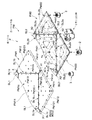
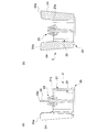
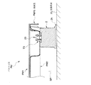
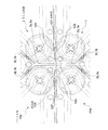
本発明に係る床パネルPは、図1、図2などに示すように、所定部位に形成した分画開口部によって分画された複数の単位パネルを有する平面視略正方形状のパネル本体PMと、隣接する単位パネルのコーナー部が集合する部位を支持する支持脚たる第1支持脚1と、パネル本体PMの四つの隅部をそれぞれ支持する第2支持脚2と、パネル本体PMの略中央部を支持する第3支持脚3とを備えたものである。そして、パネル本体PMを第1支持脚1、第2支持脚2、第3支持脚3に支持させた状態で、当該床パネルPを、例えば、建築床面FL(図14、図15参照。)に複数並べて敷設することにより、パネル本体PMと建築床面FLとの間にコード類を配線可能な二重床としての機能を発揮するようにしている。
The floor panel P according to the present invention includes a panel body PM having a substantially square shape in plan view and having a plurality of unit panels that are fractionated by a fractional opening formed in a predetermined portion, as shown in FIGS. A
より具体的に各部を説明する。 Each part will be described more specifically.
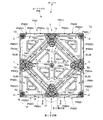
パネル本体PMは、概略平板状の表材PM1と、この表材PM1の下面側に位置する裏材PM2とを重合させるとともに、これら表材PM1と裏材PM2とを後述する適宜の手段で一体的に連結したものとしている。 The panel main body PM polymerizes a substantially flat surface material PM1 and a backing material PM2 located on the lower surface side of the surface material PM1, and integrates the surface material PM1 and the backing material PM2 by appropriate means to be described later. Are consolidated.
さらに、この表材PM1と裏材PM2とについて説明すると、表材PM1は、薄板状のスチール素材を塑性変形加工することにより形成されたものであり、4つの辺に囲まれた平面視略正方形状をなす面板部PM1aと、この面板部PM1aの各辺から垂下して設けた側縁部PM1bとを備えている。面板部PM1aには、各辺の中点X1から面板部PM1aの中心部に向かって所定距離延びる第1表材スリットSL1aと、隣り合う第1表材スリットSL1aの内方端部(面板部PM1aの中心側に位置する端部)同士を結ぶ線に沿って延びる第2表材スリットSL1bとを形成するとともに、これら第1表材スリットSL1a及び第2表材スリットSL1bにより分画開口部たる表材分画開口部SL1を構成し、この表材分画開口部SL1によって一枚の表材PM1が複数の単位パネル(1つの第1表材単位パネルPM11及び4つの第2表材単位パネルPM12)に分画されるようにしている。具体的には、第1表材単位パネルPM11は、4つの第2表材スリットSL1bに囲まれ、面板部PM1aの中央部に位置する平面視略正方形状のものである。第2表材単位パネルPM12は、1つの第2表材スリットSL1b、この第2表材スリットSL1bの両端からそれぞれ延びる第1表材スリットSL1a及びこれら各第1表材スリットSL1aの外方端部(面板部PM1aの反中心側に位置する端部)から第2表材スリットSL1bに対向する表材PM1のコーナー部に向かって延びる2つの辺PM121によって囲まれ、表材PM1の隅部を構成するようにした平面視略五角形状のものである。なお、各第2表材スリットSL1bの略中間部位には、表材PM1の肉厚方向に貫通していない接続部たる表材接続部PM1Xを設け、この表材接続部PM1Xにより第1表材単位パネルPM11と第2表材単位パネルPM12とが一部において連続するようにしている。また、各側縁部PM1bの中央部には、前記第1表材スリットSL1aの外方端部から側縁部PM1bに下方に向かって延びる第3表材スリットSL1cを形成している。また、各第2表材単位パネルPM12には、後述する裏材PM2に設けた突部PM22Tを収容し得る収容部PM12Sを形成してある。これら突部PM22Tと収容部PM12Sとが、位置ずれ抑制手段としての機能を発揮する。
各収容部PM12Sは、本実施形態では、下方に窪ませてなる平面視円形状の有底のものとしているが、例えば、貫通させた無底のものなど、これに限られない。
Further, the front material PM1 and the back material PM2 will be described. The front material PM1 is formed by plastic deformation of a thin steel material, and is substantially square in plan view surrounded by four sides. A face plate portion PM1a having a shape and a side edge portion PM1b provided to hang from each side of the face plate portion PM1a are provided. The face plate portion PM1a includes a first surface material slit SL1a extending a predetermined distance from the center X1 of each side toward the center portion of the surface plate portion PM1a, and an inner end portion (face plate portion PM1a of the adjacent first surface material slit SL1a. And a second surface material slit SL1b extending along a line connecting them), and a surface that is a fractional opening by the first surface material slit SL1a and the second surface material slit SL1b. The material fraction opening SL1 is configured, and one surface material PM1 is composed of a plurality of unit panels (one first surface material unit panel PM11 and four second surface material unit panels PM12) by the surface material fraction opening SL1. ). Specifically, the first surface material unit panel PM11 is surrounded by four second surface material slits SL1b and has a substantially square shape in plan view located at the center of the face plate portion PM1a. The second surface material unit panel PM12 includes one second surface material slit SL1b, a first surface material slit SL1a extending from both ends of the second surface material slit SL1b, and outer ends of the first surface material slits SL1a. Surrounded by two sides PM121 extending toward the corner portion of the surface material PM1 facing the second surface material slit SL1b from the end portion located on the opposite side of the face plate portion PM1a, the corner portion of the surface material PM1 is configured. The plan view has a substantially pentagonal shape. In addition, the surface material connection part PM1X which is a connection part which has not penetrated in the thickness direction of the surface material PM1 is provided in a substantially intermediate portion of each second surface material slit SL1b, and the first surface material is formed by the surface material connection part PM1X. The unit panel PM11 and the second surface material unit panel PM12 are partially continuous. Further, a third surface material slit SL1c extending downward from the outer end portion of the first surface material slit SL1a to the side edge portion PM1b is formed at the center of each side edge portion PM1b. Each second front material unit panel PM12 is formed with a housing part PM12S capable of housing a protrusion PM22T provided on a back material PM2 described later. These protrusions PM22T and the housing part PM12S exhibit a function as a positional deviation suppression means.
In the present embodiment, each housing portion PM12S has a bottomed shape with a circular shape in plan view that is recessed downward, but is not limited to this, for example, a bottomless one that is penetrated.
一方、裏材PM2は、薄板状のスチール素材を塑性変形加工することにより形成されたものであり、4つの辺によって囲まれた平面視略正方形状をなし、前記表材分画開口部SL1の投影位置に沿う位置に分画開口部たる裏材分画開口部SL2を形成している。具体的には、各辺の中点X2から裏材PM2の中心部に向かって所定距離延びる第1裏材スリットSL2aと、隣り合う第1裏材スリットSL2aの内方端部(裏材PM2の中心側に位置する端部)同士を結ぶ線に沿って延びる第2裏材スリットSL2bとを形成し、これら第1裏材スリットSL2a及び第2裏材スリットSL2bにより裏材分画開口部SL2を構成し、この裏材分画開口部SL2によって一枚の裏材PM2が複数の単位パネル(1つの第1裏材単位パネルPM21及び4つの第2裏材単位パネルPM22)に分画されるようにしている。具体的には、第1裏材単位パネルPM21は、4つの第2裏材スリットSL2bに囲まれ、裏材PM2の中央部に位置する平面視略正方形状のものである。第2裏材単位パネルPM22は、1つの第2裏材スリットSL2b、この第2裏材スリットSL2bの両端からそれぞれ延びる第1裏材スリットSL2a及びこれら各第1裏材スリットSL2aの外方端部(裏材PM2の反中心側に位置する端部)から第2裏材スリットSL2bに対向する裏材PM2のコーナー部に向かって延びる2つの辺PM221によって囲まれ、裏材PM2の4つの隅部にそれぞれ位置する平面視略五角形状のものである。なお、各第2裏材スリットSL2bの略中間部位に、裏材PM2の肉厚方向に貫通していない接続部たる裏材接続部PM2Xを設け、この裏材接続部PM2Xにより第1裏材単位パネルPM21と第2裏材単位パネルPM22とをそれぞれ一部において連続させている点も表材PM1と同様である。 On the other hand, the backing PM2 is formed by plastically deforming a thin steel material, has a substantially square shape in plan view surrounded by four sides, and is formed on the surface material partition opening SL1. A backing fraction opening SL2 that is a fraction opening is formed at a position along the projection position. Specifically, the first backing slit SL2a extending a predetermined distance from the middle point X2 of each side toward the center of the backing PM2, and the inner end portion of the adjacent first backing slit SL2a (of the backing PM2) A second backing slit SL2b extending along a line connecting the ends) located on the center side, and the backing fraction opening SL2 is formed by the first backing slit SL2a and the second backing slit SL2b. The single backing material PM2 is divided into a plurality of unit panels (one first backing material unit panel PM21 and four second backing material unit panels PM22) by the backing material separation opening SL2. I have to. Specifically, the first backing unit panel PM21 is surrounded by four second backing slits SL2b and has a substantially square shape in plan view located at the center of the backing PM2. The second backing unit panel PM22 includes one second backing slit SL2b, a first backing slit SL2a extending from both ends of the second backing slit SL2b, and an outer end portion of each of the first backing slit SL2a. The four corners of the backing PM2 are surrounded by two sides PM221 extending from (the end located on the opposite side of the backing PM2) to the corner of the backing PM2 facing the second backing slit SL2b. Are substantially pentagonal in plan view. A backing material connection part PM2X, which is a connection part that does not penetrate in the thickness direction of the backing material PM2, is provided at a substantially intermediate portion of each second backing material slit SL2b, and a first backing material unit is provided by this backing material connection part PM2X. The point that the panel PM21 and the second backing unit panel PM22 are partially continuous is also the same as the surface material PM1.
しかして、裏材PM2は、表材PM1と重合させた状態において、図2に示すように、表材PM1の下面側に密接する平板部PM2mと、裏材PM2の強度を確保すべく絞り加工により溝状に形成された補強部PM2nとを有し、部分的に凹凸形状をなすように形成されている。具体的には、平板部PM2mについては、第1裏材単位パネルPM21及び各第2裏材単位パネルPM22の各周縁部と、第1裏材単位パネルPM21及び各第2裏材単位パネルPM22の中央部位を平板部PM2mとしている。なお、その平板部PM2mのうち、各第2裏材単位パネルPM22の略中央部の平板部PM2mは、平面視略三角形状をなすものとし、また、第1裏材単位パネルPM21の略中央部に対向させるようにして設けた4つの平板部PM2mは、それぞれ平面視略三角形状をなすものとしている。一方、補強部PM2nについては、第1裏材単位パネルPM21及び各第2裏材単位パネルPM22の各周縁部位に沿った所定部位を、補強部PM2nとしてる。ここで、その所定部位とは、第1裏材単位パネルPM21の略中央部に対向させるようにして設けた4つの平板部PM2mに係るものについては、それぞれの平板部PM2mが、他の平板部PM2m及び第1裏材単位パネルPM21の周縁部に対して側面視略凹溝状に接続される部位としている。また、各第2裏材単位パネルPM22の略中央部の平板部PM2mに係るものについては、その平板部PM2mが、第2裏材単位パネルPM22の周縁部に対して側面視略凹溝状に接続される部位としている。 Thus, the backing material PM2 is drawn to ensure the strength of the backing material PM2 and the flat plate portion PM2m in close contact with the lower surface side of the backing material PM1, as shown in FIG. And a reinforcing portion PM2n formed in a groove shape, and is formed to have a partially uneven shape. Specifically, for the flat plate portion PM2m, the peripheral portions of the first backing unit panel PM21 and each second backing unit panel PM22, and the first backing unit panel PM21 and each second backing unit panel PM22. The central part is a flat plate portion PM2m. Of the flat plate portions PM2m, the flat plate portion PM2m at the substantially central portion of each second backing unit panel PM22 has a substantially triangular shape in plan view, and the substantially central portion of the first backing unit panel PM21. The four flat plate portions PM2m provided so as to face each other have a substantially triangular shape in plan view. On the other hand, for the reinforcing part PM2n, a predetermined part along each peripheral part of the first backing unit panel PM21 and each second backing unit panel PM22 is set as the reinforcing part PM2n. Here, with respect to the four portions of the flat plate portion PM2m provided so as to be opposed to the substantially central portion of the first backing unit panel PM21, the predetermined portion is the other flat plate portion. It is set as the site | part connected by the side view substantially concave groove shape with respect to the peripheral part of PM2m and 1st backing unit panel PM21. Moreover, about the thing which concerns on flat plate part PM2m of the approximate center part of each 2nd backing material unit panel PM22, the flat plate part PM2m is a side view substantially concave groove shape with respect to the peripheral part of 2nd backing material unit panel PM22. It is a connected part.
また、図1、図2に示すように、第1裏材単位パネルPM21の各コーナー部に後述する第1支持脚1の第1突起部113が取付可能な第1取付口T1を形成するとともに、第1裏材単位パネルPM21の中央に後述する第3支持脚3が取付可能な第4取付口T4を形成してある。一方、第2裏材単位パネルPM22の各コーナー部のうち、第1裏材単位パネルPM21及び他の第2裏材単位パネルPM22に隣接するコーナー部に後述する第1支持脚1の第2突起部123が取付可能な第2取付口T2を形成するとともに、第1裏材単位パネルPM21及び他の第2裏材単位パネルPM22に隣接しないコーナー部、すなわち裏材PM2の四隅の隅部に後述する第2支持脚2が取付可能な第3取付口T3を形成してある。これら第1取付口T1、第2取付口T2、第3取付口T3及び第4取付口T4(以下、取付口Tと総称する。)は、何れも補強部PM2nの前記面板部PM1aに対して平行な面に形成され、その面の肉厚方向に貫通している。第1取付口T1、第3取付口T3及び第4取付口T4は、平面視円形状をなし、第2取付口T2のみが、平面視長円形状をなすようにしている。なお、本実施形態では、第2取付口T2が、裏材PM2に設けた複数の第2裏材スリットSL2bのうち、当該第2取付口T2に最も近接している第2裏材スリットSL2b(換言すれば、第2表材スリットSL1b)の長手方向と直交する方向に、長手寸法を有するようにしている(図16参照。)。
As shown in FIGS. 1 and 2, a first attachment port T1 to which a
また、複数のパネル本体PMを積み重ねて収納などする際に、それら複数のパネル本体PMのスタッキング(図18参照。)を好適に行うために、第2裏材単位パネルPM22には、前記表材PM1の第2表材単位パネルPM12に形成した収容部PM12Sと対応する箇所に、その収容部PM12Sに収容され得る突部PM22Tを複数設けている(図1、図2参照。)。各突部PM22Tは、補強部PM2nよりもさらに下方に突出させたものであり、本実施形態においては、4つの第2裏材単位パネルPM22のうち、裏材PM2の対角線状線上に位置する一対の第2裏材単位パネルPM22にそれぞれ突部PM22Tを設けている(図2参照。)。 Further, when stacking and storing a plurality of panel main bodies PM, in order to suitably stack the plurality of panel main bodies PM (see FIG. 18), the second backing unit panel PM22 includes the surface material. A plurality of protrusions PM22T that can be accommodated in the accommodation part PM12S are provided at locations corresponding to the accommodation part PM12S formed in the second surface material unit panel PM12 of PM1 (see FIGS. 1 and 2). Each protrusion PM22T protrudes further downward than the reinforcing part PM2n. In the present embodiment, of the four second backing unit panels PM22, a pair positioned on the diagonal line of the backing PM2. Each of the second backing unit panels PM22 is provided with a protrusion PM22T (see FIG. 2).
これら表材PM1の下面側と裏材PM2の上面側とを重合させて、複数箇所を適宜の手段(例えば、スポット溶接など)で連結することにより、表材PM1と裏材PM2とを一体的に組み付けてなる一のパネル本体PMが形成される。このパネル本体PMは、表材PM1と裏材PM2とを組み付けた状態において、第1表材単位パネルPM11と第1裏材単位パネルPM21とが重合するとともに、各第2表材単位パネルPM12と各第2裏材単位パネルPM22とが重合し、表材PM1及び裏材PM2それぞれに形成した表材分画開口部SL1及び裏材分画開口部SL2(以下、分画開口部SLと総称する。)を介して上述した重合関係にある第1表材単位パネルPM11と第1裏材単位パネルPM21とが第1単位パネルとして、また、各第2表材単位パネルPM12と各第2裏材単位パネルPM22とが第2単位パネルとして、おのおの同時に変形するように設定している。しかして、このパネル本体PMは、分画開口部SLを介して隣接する第1単位パネルと第2単位パネルとを相対変位させ得るように構成されている。そして、隣接する第1単位パネルと第2単位パネルと(以下、第1単位パネルと第2単位パネルとを「単位パネル」と総称する。)のコーナー部同士が集合する部位(以下、コーナー部集合部位とする。)に、後述する第1支持脚1を取り付けることができるようにしている。
By superposing the lower surface side of the front material PM1 and the upper surface side of the back material PM2 and connecting a plurality of locations by appropriate means (for example, spot welding), the front material PM1 and the back material PM2 are integrated. One panel main body PM assembled to is formed. In the panel body PM, in a state where the front material PM1 and the back material PM2 are assembled, the first front material unit panel PM11 and the first back material unit panel PM21 are superposed, and each second front material unit panel PM12 Each of the second backing unit panels PM22 is polymerized to form a front material fraction opening SL1 and a backing material fraction opening SL2 (hereinafter collectively referred to as a fraction opening SL) formed in the front material PM1 and the back material PM2, respectively. The first front panel unit panel PM11 and the first back panel unit panel PM21, which are in the above-described polymerization relationship via the above-described), serve as the first unit panel, and each second front panel unit panel PM12 and each second back panel. The unit panel PM22 is set as a second unit panel so as to be simultaneously deformed. Thus, the panel body PM is configured to be able to relatively displace the first unit panel and the second unit panel which are adjacent to each other through the fraction opening SL. And the part (henceforth a corner part) where the corner parts of the adjoining 1st unit panel and 2nd unit panel (henceforth a 1st unit panel and a 2nd unit panel are named generically "unit panel") gather. The
さらに、本実施形態では、裏材PM2に形成した第2取付口T2は、平面視長円形状を有しているため、この第2取付口T2に第1支持脚1の第2突起部123を取り付けた場合には、この第2突起部123は、裏材PM2に対して「遊びをもって取り付けられる状態」を有するようになる。すなわちこの取付状態において前記単位パネル同士の相対変位に伴って前記第2突起部123と第2取付口T2との相対位置が変化することにより、単位パネル同士(すなわち、第1単位パネルと第2単位パネル同士)の相対移動を許容する許容手段としての機能を発揮する。なお、本実施形態では、裏材PM2に形成した第1取付口T1と、第1支持脚1の第1突起部113とを取り付けた場合には、この第1突起部113が、裏材PM2に対して「遊びを生じることなく嵌合した状態」を有するように構成している。
Furthermore, in this embodiment, since the 2nd attachment port T2 formed in back material PM2 has a planar view ellipse shape, the
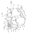
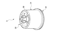
第1支持脚1は、図3、図4、図5、図6、図7、図8、図16等に示すように、コーナー部集合部位に隣接する各単位パネルの枚数に対応して設けた複数の脚本体と、これら脚本体同士を連結する連結部13とを備えたものである。具体的には、第1支持脚1は、例えば合成樹脂素材からなる一体成形品であり、コーナー部集合部位における第1裏材単位パネルPM21のコーナー部周辺を支持し得る第1脚本体11と、コーナー部集合部位において第1裏材単位パネルPM21に隣接する第2裏材単位パネルPM22のコーナー部周辺を支持し得る一対の第2脚本体12と、これら各脚本体を一体に連結する連結部13とを備えている。なお、本実施形態では、これら各脚本体11、12の中心部同士を結ぶ線分が第1脚本体11の中心部を頂点とする平面視略二等辺三角形状となるように各脚本体11、12を配置している(図4参照。)。またこのとき、一対の第2脚本体12を、当該床パネルPを平面視した際に、後述する位置決め手段がパネル本体PMから突出する位置に位置付けられるように、パネル本体PMの各側縁部PM1bにおいて並べて配置するようにしている。また、第1脚本体11および第2脚本体12の上端側を硬質樹脂とする一方、第1脚本体11および第2脚本体12の下端側(特に建築床面FLと接触する部位)及び連結部13を軟質樹脂とするとともに、これら各部を一体に射出成形によって形成する2色(異材質)成形方法を採用するようにしている。
As shown in FIGS. 3, 4, 5, 6, 7, 8, 8, and 16 etc., the
以下、各部についてより具体的に説明すると、第1脚本体11は、概略円筒状をなす第1周壁部111と、第1周壁部111の内周に平面視略十字状に設けられ第1周壁部111と略同じ高さ寸法を有する第1リブ112と、第1リブ112同士が交叉する部位に関連付けて設けられ第1周壁部111の上端より上方に突出させてなる突起部たる第1突起部113とを有する。この第1突起部113は、前記裏材PM2の第1裏材単位パネルPM21のコーナー部に形成した第1取付口T1に係合可能なものであり、第1突起部113の軸中心を中心として十字状をなすように形成したスリット113Sと、このスリット113Sを挟むように配置した弾性変形し得る4つの弾性部1131とを備えている。そして、各弾性部1131には、その先端部に鉤状の係合片1131aを一体に備えるようにしている。また、第1周壁部111と第1リブ112との間には、後述する高さ調節部材たる第1ライナーR1に設けた第1挿入部が挿入可能な概略円筒状をなす挿入穴たる第1挿入穴11Xを設けている。さらに、第1周壁部111の外周には、第2脚本体12側に向かって延出させてなる一対の鍔部114を設けている。そして、この鍔部114の上端が、第1周壁部111の上端及び突起部の上端よりもさらに上方に位置するように設定している。また、第1周壁部111の下端部における径が第1周壁部111の他の部位より若干大径となるように設定するとともに、この第1周壁部111の下端側に、建築床面FLに接地し得る円環状の第1接地部115を設けている。さらにまた、本実施形態では、この第1周壁部111の高さ寸法と、後述する第2支持脚2を構成する隅部支持用周壁部21の高さ寸法と、後述する第3支持脚3の中央支持用周壁部31の高さ寸法とを、略同一に構成している。
Hereinafter, each part will be described in more detail. The
一方、各第2脚本体12は、概略円筒状をなし前記第1脚本体11の第1周壁部111より大きい高さ寸法を有する第2周壁部121と、第2周壁部121の内周に平面視略十字状に設けられ前記第1周壁部111と略同じ高さ寸法を有する第2リブ122と、第2リブ122同士が交叉する部位に関連付けて設けられ第2リブ122の上端より上方に突出させてなる突起部たる第2突起部123とを有する。
On the other hand, each second leg
さらに詳述すると、第2周壁部121は、その上縁が前記第1脚本体11の鍔部114の上縁と略同じ高さ位置となるように設定されており、第2周壁部121の一部に第2リブ122の上縁と略同じ高さ位置まで切り欠いてなる切欠部124を形成してある。そして、各第2脚本体12をそれぞれ対応する第2裏材単位パネルPM22のコーナー部に取り付けた場合に、第2周壁部121の上縁が第2裏材単位パネルPM22の平板部PM2mに当接するとともに、切欠部124によって第2周壁部121の上縁と第2裏材単位パネルPM22の補強部PM2nとの干渉を回避し、切欠部124に第2裏材単位パネルPM22の補強部PM2nが位置するように設定している。
More specifically, the second
第2突起部123は、前記裏材PM2の第2裏材単位パネルPM22のコーナー部に形成した第2取付口T2に係合可能なものであり、前記第1脚本体11の第1突起部113と略同様の形状をなすものである。
The
加えて、本実施形態では、第2周壁部121の下端部に第2周壁部121の他の部位より若干大径となるように設定している。そして、この第2周壁部121の下端側に、建築床面FLに接地し得る第2接地部125を形成するとともに、第2周壁部121の外周に他方の第2脚本体12に向かって延出させてなる概略板状の延出部126を設けている。各延出部126は第2リブ122よりも小さい高さ寸法を有し、これら各延出部126に、前記第1脚本体11から離れる方向に概略板状の突出部127を設け、これら突出部127が各第2脚本体12の第2接地部125の外縁同士を結んた線分よりも前記第1脚本体11から離れる方向に突出するように設定している。そして、本実施形態においては、突出部127の正面視における巾寸法d1(延出部126の延出方向に沿った寸法)を、延出部126の正面視における巾寸法d2の略半分に設定し(図4参照。)、一方の第2脚本体12の延出部126には、突出部127を延出部126の基端部側に設け、他方の第2脚本体12の延出部126には、突出部127を延出部126の先端部に設けている。これにより、一対の第1支持脚1を第2脚本体12同士が当接するように対向配置した場合、対応する突出部127同士が延出方向に隣接し、第1支持脚1を、延出部126の延出方向へ相対移動することが禁止される。このように、各延出部126は、当該床パネルPの位置決めを行う位置決め手段(特に、隣接配置した床パネルP同士が所定位置よりさらに近接することを禁止する近接禁止手段)としての機能を発揮する。また、各突出部127は、当該床パネルPの位置決めを行う位置決め手段(特に、隣接配置した床パネルP同士が、それらのパネル本体PMの側縁部PM1b同士を略沿わせた状態で、所定位置よりさらに延出部126の延出方向に沿ってずれ動くことを禁止するずれ移動禁止手段)としての機能を発揮する。
In addition, in the present embodiment, the lower end portion of the second
また、一方の第2脚本体12の第2周壁部121に設定した前記第2接地部125に、他方の第2脚本体12に向かって延出する概略薄板状の舌片部128を一体に設けている。舌片部128の先端部における下面には、下方に向かって所定寸法突出させてなる突起129を設け(図3、図5、図8参照。)、図示はしていないが、この突起129を、下段側に位置付けたパネル本体PMの第1表材スリットSL1aに挿入して、複数の第1支持脚1をスタッキング可能に構成している。なお、舌片部128はある程度の柔軟性を有するものであり、第1支持脚1を建築床面FL等に接地させた場合、第1支持脚1の最下位に位置する突起129が他の部位より優先して接地するが、第1支持脚1自体の自重により突起129の突出寸法に対応して舌片部128の先端部が上方に浮き上がるように弾性変形可能に設定してある。
Further, a generally thin plate-
第2支持脚2は、図1に示すように、パネル本体PMのコーナー部であって且つ前記単位パネルが隣接しない部位において、前記建築床面FLに接地しながら前記パネル本体PMを支持するものである。なお、図示はしていないが、当該第2支持脚2と建築床面FLとの間に、床面の高さ調節をするための高さ調節部材たる第2ライナー(図示せず)を設け、当該第2支持脚2が建築床面FLに対して直接接しないようにしてもよい。
As shown in FIG. 1, the
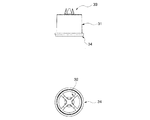
より具体的にこの第2支持脚2は、図9、図10、図11、図15などに示すように、概略円筒状をなす隅部支持用周壁部21と、隅部支持用周壁部21の内周に平面視略十字状に設けられ隅部支持用周壁部21と略同じ高さ寸法を有する隅部支持用リブ22と、隅部支持用リブ22同士が交叉する部位に関連付けて設けられ隅部支持用周壁部21の上端より上方に突出させてなる突起部たる隅部支持用突起部23と、前記隅部支持用周壁部21の外周に設けた4枚の隅部支持用羽根部24とを具備し、これら各部を合成樹脂により一体に形成した一体成形品である。
More specifically, as shown in FIGS. 9, 10, 11, and 15 and the like, the
さらに各部を詳述すると、隅部支持用周壁部21は、その上端部に、当該第2支持脚2を前記パネル本体PMに取り付けた状態において前記裏材PM2の前記補強部PM2nを支持し得る第1支持部21aを有している。また、隅部支持用周壁部21の下端部における径が隅部支持用周壁部21の他の部位より若干大径となるように設定するとともに、この隅部支持用周壁部21の下端側に、建築床面FLに接地し得る円環状の隅部支持用接地部25を設けている。
More specifically, each corner supporting
隅部支持用リブ22は、前記第1脚本体11の第1リブ112と略同様のものであるので説明を省略する。
The
隅部支持用突起部23は、第1裏材単位パネルPM21及び他の第2裏材単位パネルPM22に隣接しないコーナー部、すなわち裏材PM2の四隅の隅部に形成した第3取付口T3に係合可能なものであり、その構成は、前記第1脚本体11の第1突起部113と略同様であるので説明を省略する。
The
隅部支持用羽根部24は、隅部支持用周壁部21から外方に向かって延出する薄板状のものであって、その上端部に、当該第2支持脚2を前記パネル本体PMに取り付けた状態において前記裏材PM2の前記平板部PM2mを支持し得る第2支持部24aを有している。また、この隅部支持用羽根部24の上端が、隅部支持用周壁部21の上端及び突起部の上端よりもさらに上方に位置するように設定している。さらに、本実施形態では、4枚の隅部支持用羽根部24のうち2枚の隅部支持用羽根部24を平面視略直線状を成すとともに前記隅部支持用周壁部21を挟むように配置し、他の2枚の隅部支持用羽根部24を平面視略ハの字状に配置することにより、4枚の隅部支持用羽根部24に設けた第2支持部24aが、パネル本体PMの隅部にある裏材PM2の平板部PM2mを支持するように、換言すれば、この第2支持部24aが、前記第1支持部21aよりもさらにパネル本体PMの縁部に近い部位を支持するように構成している。
The corner
第3支持脚3は、図1に示すように、パネル本体PMの略中央部において、前記建築床面FLに接地しながら前記パネル本体PMを支持するものである。なお、図示はしていないが、当該第3支持脚3と建築床面FLとの間に、床面の高さ調節をするための高さ調節部材たる第3ライナー(図示せず)を設け、当該第3支持脚3が建築床面FLに対して直接接しないようにしてもよい。 As shown in FIG. 1, the third support leg 3 supports the panel body PM while being in contact with the building floor surface FL at a substantially central portion of the panel body PM. Although not shown, a third liner (not shown) as a height adjustment member for adjusting the height of the floor surface is provided between the third support leg 3 and the building floor surface FL. The third support leg 3 may not be in direct contact with the building floor surface FL.
より具体的にこの第3支持脚3は、図12、図13などに示すように、概略円筒状をなす中央支持用周壁部31と、中央支持用周壁部31の内周に平面視略十字状に設けられ中央支持用周壁部31と略同じ高さ寸法を有する中央支持用リブ32と、中央支持用リブ32同士が交叉する部位に関連付けて設けられ中央支持用周壁部31の上端より上方に突出させてなる突起部たる中央支持用突起部33とを具備し、これら各部を合成樹脂により一体に形成した一体成形品である。
More specifically, as shown in FIGS. 12 and 13, the third support leg 3 includes a central support
さらに各部を詳述すると、中央支持用周壁部31は、第2支持脚2の隅部支持用周壁部21と略同様のものであるので説明を省略する。なお、本実施形態では、この中央支持用周壁部31の下端側に、建築床面FLに接地し得る円環状の中央支持用接地部34を設けている。
Further, each part will be described in detail. The central support
中央支持用リブ32は、前記第1脚本体11の第1リブ112と略同様のものであるので説明を省略する。
The
中央支持用突起部33は、裏材PM2の第4取付口T4に係合可能なものであり、その構成は、前記第1脚本体11の第1突起部113と略同様であるので説明を省略する。
The
なお、本実施形態では、図8等に示すように、高さ調節部材たる第1上ライナーR11および高さ調節部材たる第1下ライナーR12(以下、第1ライナーR1と総称する。)を、層状に重合配置可能に構成することにより、当該床パネルPが、前記建築床面FLの不陸に対応し得るものとなるようにしている。 In the present embodiment, as shown in FIG. 8 and the like, the first upper liner R11 as a height adjusting member and the first lower liner R12 as a height adjusting member (hereinafter collectively referred to as a first liner R1) are used. The floor panel P is configured to be able to cope with the unevenness of the building floor surface FL by being configured so as to be superposed in layers.
具体的には、第1上ライナーR11を、単独で前記第1支持脚1の下面側に取り付ける態様(第1取付態様)と、前記第1上ライナーR11と第1下ライナーR12とを重ねた状態で前記第1支持脚1の下面側に取り付ける態様(第2取付態様)とを取り得るようにしており、建築床面FLの不陸に対して適宜対応し得るようにしている。
Specifically, a mode (first mounting mode) in which the first upper liner R11 is independently attached to the lower surface side of the
各部を詳述すると、第1上ライナーR11は、概略薄板状の上ライナー面板部R111と、この上ライナー面板部R111の周端を略直角に起立させた上ライナー起立壁R112とを備えてなる。より具体的に、上ライナー面板部R111は、前記第1支持脚1の下面側を略覆い得る平面視略三角形状をなすものである。また、この上ライナー面板部R111の略中央部で且つ当該第1上ライナーR11と前記第1支持脚1とを取り付けた際にその第1支持脚1の第1挿入穴11Xと対応する位置に、円筒状の第1挿入部R11Xを設けている。
More specifically, the first upper liner R11 includes a substantially thin plate-like upper liner surface plate portion R111, and an upper liner standing wall R112 in which the peripheral end of the upper liner surface plate portion R111 is erected at a substantially right angle. . More specifically, the upper liner face plate portion R111 has a substantially triangular shape in plan view that can substantially cover the lower surface side of the
第1下ライナーR12は、概略薄板状の下ライナー面板部R121と、この下ライナー面板部R121の周端を略直角に起立させた下ライナー起立壁122とを備えてなる。より具体的に、下ライナー面板部R121は、前記第上ライナー面板部R111に重合配置してその下面側を略覆い得る平面視略三角形状をなすものである。また、この下ライナー面板部R121の略中央部で且つ当該第1下ライナーR12と前記第1上ライナーR11とを十合配置した際にその第1上ライナーR11の第1挿入部R11Xに挿入される円筒状の第2挿入部R12Xを設けている。そして、第1上ライナーR11と第1下ライナーR12とを重合配置した際に、上ライナー起立壁R112が下ライナー起立壁122に呑み込まれるように、下ライナー面板部R121を上ライナー面板部R111よりも若干大きく構成している。
The first lower liner R12 includes a substantially thin plate-like lower liner surface plate portion R121, and a lower
以下、上述のように構成される床パネルPの使用方法について、(1)床パネルPの敷設方法、(2)敷設後の二重床としての使用方法、および(3)床パネルPの収納方法に分けて具体的に説明を行う。 Hereinafter, regarding the usage method of the floor panel P configured as described above, (1) the installation method of the floor panel P, (2) the usage method as a double floor after installation, and (3) the storage of the floor panel P Specific explanation will be given by dividing into methods.
(1)床パネルPの敷設方法について。 (1) About laying method of floor panel P.
まず、パネル本体PMの第1取付口T1に対して第1支持脚1の第1突起部113をそのパネル本体PMの下方から挿入するとともに、パネル本体PMの第2取付口T2に対して第1支持脚1の第2突起部123をそのパネル本体PMの下方から挿入することにより、パネル本体PMと第1支持脚1とを取り付ける。同様にして、パネル本体PMと第2支持脚2および第3支持脚3とを取り付けることにより、床パネルPを完成させる。このとき、パネル本体PMを、天地を逆にするなどして、第1支持脚1などを取り付けるようにしてもよい。このように、パネル本体PMに第1支持脚1等を予め取り付けておくことで、施工時間の短縮などを図ることができる。
First, the
そして、建築床面FLの適宜位置に、一の床パネルPを配置する。なお、床パネルPの第1支持脚1を建築床面FL等に接地させた場合、第1支持脚1の最下位に位置する突起129が他の部位より優先して接地するが、第1支持脚1自体の自重により突起129の突出寸法に対応して舌片部128の先端部が弾性変形して上方に浮き上がる(図示せず。)ので、この突起129が、床パネルPの配置の妨げとなることは無い。
And the one floor panel P is arrange | positioned in the appropriate position of the building floor surface FL. In addition, when the
次に、建築床面にFLに配置済みの一の床パネルPに対して、他の床パネルPを整列させて配置する。このとき、まず、両方の床パネルPの側縁部PM1b同士を沿わすように配置してから、側縁部PM1b同士を沿わすようにしながら他の床パネルPを移動して整列させても良いし、あるいは、両床パネルPをある程度整列させた状態においてから、他の床パネルPを一の床パネルPに近づけて整列させても良い。 Next, the other floor panel P is arranged and arranged with respect to the one floor panel P already arranged in the FL on the building floor. At this time, after arranging the side edge portions PM1b of both floor panels P along the side edge portions PM1b, other floor panels P may be moved and aligned along the side edge portions PM1b. Alternatively, after the two floor panels P are aligned to some extent, the other floor panels P may be aligned close to one floor panel P.
しかして、一の床パネルPと他の床パネルPとが整列する状態になると、双方に設けている位置決め手段同士が当接を行う。この状態で、一の床パネルPを他の床パネルPに対して、近接する向きに外力(図示せず)を加えても、一の床パネルPの位置決め手段と他の床パネルPの位置決め手段とが、当接するため(図17参照。)、双方の床パネルPは、その場に留まり続ける。したがって、双方のパネル本体PM同士も当接することが無く、パネル本体PM同士が当接することにより生じる金属音の発生は起こらない。また、両方の床パネルPの側縁部PM1b同士を沿わすようにしながら他の床パネルPを移動して整列させたその向きと同方向に外力(図示せず)を加えても、双方の床パネルPの突出部126同士が当接するため、双方の床パネルPは、その場に留まり続ける。
Thus, when one floor panel P and another floor panel P are aligned, the positioning means provided on both floors come into contact with each other. In this state, even if an external force (not shown) is applied in the direction in which one floor panel P is adjacent to the other floor panel P, the positioning means of one floor panel P and the positioning of the other floor panel P Both floor panels P remain in place because the means abut (see FIG. 17). Therefore, both panel main bodies PM are not in contact with each other, and no metal sound is generated when the panel main bodies PM are in contact with each other. Further, even if an external force (not shown) is applied in the same direction as the direction in which the other floor panels P are moved and aligned while keeping the side edges PM1b of both floor panels P along each other, Since the
このようにして、複数の床パネルPを建築床面FL上に整列させて適宜配置することができる。 In this way, a plurality of floor panels P can be arranged appropriately on the building floor FL.
なお、一般的な建築床面FLは、通常若干の不陸を有しているが、このような不陸を有する建築床面FLに対して床パネルPを配置した場合でも、効果的にその不陸を吸収することができる。 In addition, although a general building floor FL usually has a slight unevenness, even when the floor panel P is arranged on the building floor FL having such an unevenness, the floor is effectively Can absorb unevenness.
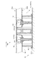
具体的には、裏材PM2に形成した第2取付口T2は、平面視長円形状を有しているため、図14に示すように、この第2取付口T2に第1支持脚1の第2突起部123を取り付けた場合には、この第2突起部123は、裏材PM2に対して「遊びをもって取り付けられる状態」を有するようになる。すなわちこの取付状態において前記単位パネル同士の相対変位に伴って前記第2突起部123と第2取付口T2との相対位置が変化することにより、単位パネル同士(すなわち、第1単位パネルと第2単位パネル同士)の相対移動を許容する許容手段としての機能を発揮する。したがって、一方の単位パネル側に凸状の不陸があると、その不陸に対応すべく第2取付口T2内を第2突起部123が移動して、すなわち、第2取付口T2と第2突起部123との取付位置が相対的に変化して、これにともない、単位パネル同士も相対変位する。また、このとき、連結部13も、単位パネルの変形に伴って変形し得るので、単位パネル同士の相対変位が円滑に行われる。このようにして、効果的に不陸を吸収することができる。
Specifically, since the second mounting port T2 formed in the backing PM2 has an oval shape in plan view, as shown in FIG. 14, the second mounting port T2 has the
(2)敷設後の二重床としての使用方法。 (2) Usage as a double floor after laying.
複数の床パネルPを建築床面FL上に敷設し、パネル本体PMと建築床面FLとの間の空間SP(図14、図15参照。)に、例えば、配線類(図示せず)を通せば、床パネルPの表面側にそれら配線類が露出することを効果的に防止できるので、オフィス空間内に配線類が無駄に露出しないといった非常に見栄えのよいオフィスレイアウトを行うことができる。 A plurality of floor panels P are laid on the building floor surface FL, and, for example, wiring (not shown) is provided in a space SP (see FIGS. 14 and 15) between the panel body PM and the building floor surface FL. If it is passed, it is possible to effectively prevent the wirings from being exposed on the surface side of the floor panel P. Therefore, it is possible to perform a very attractive office layout in which the wirings are not unnecessarily exposed in the office space.
このとき、図17に示すように、隣接する床パネルPの位置決め手段が、略常時当接する状態にあり、隣接するパネル本体PM同士が直接当接することはない。したがって、床パネルP上を歩行したとしても、パネル本体PM同士が当接することにより生じる金属音(ここでは、歩行音に類される。)の発生もない。 At this time, as shown in FIG. 17, the positioning means of the adjacent floor panel P is in a state of being in constant contact, and the adjacent panel bodies PM are not in direct contact with each other. Therefore, even if the user walks on the floor panel P, there is no generation of a metal sound (here, similar to a walking sound) that occurs when the panel main bodies PM come into contact with each other.
しかも、床パネルPMを金属製のものとしているため、床パネルP自体の剛性を効果的に確保でき、好適な歩行感を得られる。 Moreover, since the floor panel PM is made of metal, the rigidity of the floor panel P itself can be effectively secured, and a suitable walking feeling can be obtained.
さらに、建築床面FLが、異なる高さを有するものであったとしても、第1支持脚1等を樹脂製のものとしているので、然るべき高さ寸法を有するものに適宜交換して、そのようなものにも有効に対応することもできる。
Furthermore, even if the building floor surface FL has a different height, the
(3)床パネルPの収納方法。 (3) A method for storing the floor panel P.
まず、第1支持脚1をパネル本体PMから取り外す向きにその第1支持脚1に外力を加えると、第1支持脚1は第1突起部113によって、パネル本体PMの第1取付口T1に、その弾性変形を利用して取り付けているだけであるので、容易に第1支持脚1を、パネル本体PMから簡単に取り外すことができる。また、同様にして、第2支持脚2および第3支持脚3を、簡単にパネル本体PMから取り外すことができる。すなわち、床パネルPを、樹脂製のものと金属性のものとに容易に分解できる。
First, when an external force is applied to the
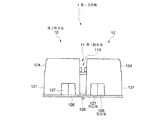
そして、面板部が上方を向くようにした一のパネル本体PMに対して、同様にした他のパネル本体PMを積み重ねる。すると、下段側のパネル本体PMの面板部に設けた収容部PM12Sに対して、上段側のパネル本体PMに設けた突部PM22Tが収納される。 And the other panel main body PM which carried out similarly is piled up with respect to one panel main body PM which made the faceplate part face upward. Then, the protrusion PM22T provided in the upper panel body PM is accommodated in the accommodation part PM12S provided in the face plate portion of the lower panel body PM.
しかして、複数のパネル本体PMを、図18に示すように、積み重ねた状態で、例えば水平方向に外力が加わったとしても、位置ずれ抑制手段としての機能を発揮する収容部PM12Sと突部PM22Tとによって、積み重ねている状態が崩れることを効果的に防止することができる。 Accordingly, as shown in FIG. 18, the housing parts PM12S and the protrusions PM22T exhibiting a function as positional deviation suppression means even when an external force is applied in the horizontal direction, for example, in a stacked state as shown in FIG. Thus, it is possible to effectively prevent the stacked state from collapsing.
なお、図示はしないが、パネル本体PMと第1支持脚1等とを分解しないで、すなわち、床パネルPを完成品のままで積み重ねても良い。
Although not shown, the panel body PM and the
この場合には、下段側のパネル本体PMの第1表材スリットSL1aに対して、上段側の第1支持脚1に設けた突起129が挿入される。しかして、複数の床パネルPを積み重ねた状態で、例えば水平方向に外力が加わったとしても、第1表材スリットSL1aと突起129とによって、積み重ねている状態が崩れることを効果的に防止することができる。
In this case, the
このように、本実施形態に係る床パネルPは、金属製のパネル本体PMと、このパネル本体PMを着脱可能に支持する樹脂製の第1支持脚1、第2支持脚2及び第3支持脚3とにより二重床を成すように床パネルPを構成し、且つ、パネル本体PMに第1支持脚1等を予め取り付けているため、近時の情報化社会に対応しつつもコンピュータ配線等によりオフィスレイアウトが乱雑になることを有効に防止でき、且つ、特にパネル本体PMによって剛性の高い床パネルPを実現できる上に、当該床パネルPの製造・組立および施工・解体も容易にでき、さらには、第1支持脚1等を取り替えるだけで、異なる高さの二重床にも対応することができ、加えて、パネル本体PMと第1支持脚1等とを分別廃棄できるので、地球環境にも優しいといった、床パネルPを実現できる。すなわち、オフィスレイアウトを見栄えよく行えるとともに、生産性や特に施工性にも優れ、且つ、環境問題にも効果的に対応可能であり、さらに比較的安価に構成できるといった、高機能な床パネルPを提供することができる。
Thus, the floor panel P according to the present embodiment includes a metal panel body PM, and a resin-made
なお、前記第1支持脚1が、前記パネル本体PMを支持する第1脚本体11及び一対の第2脚本体12とこれら脚本体11、12同士を連結する連結部13とを具備するものとしているため、これら複数の脚本体11、12によって、パネル本体PMを安定支持する機能を確保しつつも、連結部13を建築床面FL及びパネル本体PMから離間させているため、二重床部分を有効に活用することができる。
The
また、前記第1支持脚1が、当該床パネルPを平面視した際に、少なくとも一部が前記パネル本体PMの側縁より外方に突出する位置決め手段を備えるものであって、一の床パネルPに対して他の床パネルPを隣接配置する際に、一の床パネルPの位置決め手段に対して、他の床パネルPの位置決め手段を当接させて他の床パネルPの位置決めを行い得るように構成しているため、隣接する位置にある一の位置決め手段と他の位置決め手段とをそれぞれ当接させるだけで、一の床パネルPの配置位置に対する他の床パネルPの配置位置を決定できるため、床パネルPのレイアウト作業を簡単に行うことができる。また、位置決め手段は、樹脂製であるため、例えば、複数並べた状態で床パネルPを使用している際に、位置決め手段同士が擦れあっても、床パネルP同士が擦れ合うことがないので、金属同士が擦れあったときに発生するような異音が発生せず、好適に使用できる。
In addition, the
また、前記第1支持脚1が、第1脚本体11と対を成す第2脚本体12とを備えるものであって、複数の脚本体11、12のうち対を成す第2脚本体12を、前記パネル本体PMの側縁部に沿って並べて配置するとともに、その側縁部に沿って並べて配置した第2脚本体12に、前記位置決め手段を設けているため、その第2脚本体12にそれぞれ設けた位置決め手段同士を当接させて、一の床パネルPと他の床パネルPとの間に形成される隙間を、より安定して確保することができるため、前記異音の発生を確実に防止することができる。
The
このとき、前記位置決め手段が、隣接配置した床パネルP同士が所定位置よりさらに近接することを禁止する近接禁止手段としての機能を有するようにしているため、床パネルP同士を近接させて配置する際の位置決めを行い易い。 At this time, since the positioning means has a function as a proximity prohibiting means for prohibiting adjacent floor panels P from being closer to each other than a predetermined position, the floor panels P are arranged close to each other. Easy positioning.
また、側縁部PM1bに沿って並べて配置した対を成す第2脚本体12において、一の脚本体が、前記パネル本体PMの側縁部PM1bと平行を成すべく隣接する他の脚本体に向かって延出させてなり且つ前記近接禁止手段を構成する延出部126を備えるものであって、一の床パネルPに設けた延出部126と他の床パネルPに設けた延出部126とを当接させることにより、隣接する床パネルP同士が所定位置よりさらに近接することを禁止しているため、例えば、延出部126のパネル本体PMの側縁部PM1bに沿って延びる寸法を大きく設定すれば、延出部126同士の当接部分が増えるので、床パネルPを隣接配置する際に、その位置決め作業を行いやすい。
Further, in the
前記位置決め手段が、隣接配置した床パネルP同士が、それらのパネル本体PMの側縁部PM1b同士を略沿わせた状態で、所定位置よりさらに所定方向に沿ってずれ動くことを禁止するずれ移動禁止手段としての機能を有するため、一の床パネルPに対して他の床パネルPを配置する際に、所定方向における位置決めを好適に行えるうえ、床パネルP同士を所定方向に沿ってずれ動くことを効果的に禁止できる。 The positioning means prohibits the adjacently arranged floor panels P from shifting further along a predetermined direction than a predetermined position in a state in which the side edge portions PM1b of the panel main bodies PM are substantially aligned. Since it has a function as a prohibition means, when another floor panel P is arranged with respect to one floor panel P, positioning in a predetermined direction can be suitably performed, and the floor panels P are shifted along the predetermined direction. Can be effectively banned.
前記第1支持脚1が、当該床パネルPを平面視した際に、前記パネル本体PMの側縁部PM1bより外方に突出する位置に位置付けられ、且つ前記ずれ移動禁止手段を構成する突出部127を備え、一の床パネルPに設けた突出部127と他の床パネルPに設けた突出部127とを、前記所定方向において重合するように当接させることにより、隣接する床パネルP同士が所定位置よりさらに所定方向へずれることを禁止しているため、ずれ移動禁止手段を簡単な構成で実現ながらも有効な効果を得られる。
The
前記パネル本体PMが、薄板状のスチール素材を塑性変形加工することにより形成したものであるので、パネル本体PMを、剛性を確保しつつも安価なものとできる。 Since the panel body PM is formed by plastic deformation of a thin steel material, the panel body PM can be made inexpensive while ensuring rigidity.
前記第1支持脚1の建築床面FLに接する部位を軟質樹脂にて形成しているため、パネル本体PMに衝撃(例えば、歩行による震動やボールの落下など)が加わった際に、建築床面FLと第1支持脚1との間で発生する震動を、軟質樹脂部分で効果的に吸収し、床衝撃音が発生することを効果的に防止できる。
Since the portion of the
なお、本発明は、以上に詳述した実施形態に限られるものではない。 The present invention is not limited to the embodiment described in detail above.
例えば、表材PM1及び裏材PM2を、それぞれ薄板状のスチール素材を塑性変形加工することにより形成しているが、例えば、アルミダイキャスト製のものとする等、その形成方法は本実施形態に限られるものではない。 For example, the front material PM1 and the back material PM2 are each formed by plastic deformation of a thin steel material. For example, the material is made of aluminum die cast. It is not limited.
また、第1挿入孔11Xを、第1脚本体11に設けているが、第2脚本体2に設けるようにしてもよい。
Further, although the
また、第1支持脚1の構成は、本発明の支持脚としての機能を具備するものであれば、本実施形態のものに限られるものではなく、さらに第2支持脚2に本発明の支持脚としての機能を具備させても良い。
Further, the configuration of the
その他、各部の具体的構成についても上記実施形態に限られるものではなく、本発明の趣旨を逸脱しない範囲で種々変形が可能である。 In addition, the specific configuration of each part is not limited to the above embodiment, and various modifications can be made without departing from the spirit of the present invention.
FL・・・・・・・建築床面
P・・・・・・・・床パネル
PM・・・・・・・パネル本体
PM1b・・・・・側縁部
1・・・・・・・・支持脚(第1支持脚)
11・・・・・・・脚本体(第1脚本体)
12・・・・・・・脚本体(第2脚本体)
13・・・・・・・連結部
126・・・・・・位置決め手段、近接禁止手段(延出部)
127・・・・・・位置決め手段、移動禁止手段(突出部)
FL ······································ Floor panel PM Support leg (first support leg)
11 .... Leg body (first leg body)
12 .... Leg body (second leg body)
13 ....
127... Positioning means, movement prohibition means (protrusion)
Claims (10)
前記パネル本体を金属製のものとする一方、前記支持脚を樹脂製のものとし、前記パネル本体に前記支持脚を予め取り付けた状態で、前記建築床面に対して敷設するように構成していることを特徴とする床パネル。 In order to constitute a double floor, it comprises a panel body arranged at a position spaced from the building floor, and a support leg that removably supports the panel body and can be grounded to the building floor. A floor panel of a type used by arranging a plurality of the panel main bodies in a state of being supported by the support legs,
While the panel body is made of metal, the support legs are made of resin, and the panel legs are pre-attached to the panel body and laid on the building floor. A floor panel characterized by
一の床パネルに対して他の床パネルを隣接配置する際に、一の床パネルの位置決め手段に対して、他の床パネルの位置決め手段を当接させて他の床パネルの位置決めを行い得るように構成していることを特徴とする請求項1又は2記載の床パネル。 When the support leg is a plan view of the floor panel, at least a part thereof includes positioning means that protrudes outward from the side edge of the panel body,
When another floor panel is disposed adjacent to one floor panel, the other floor panel can be positioned by bringing the positioning means of the other floor panel into contact with the positioning means of the one floor panel. The floor panel according to claim 1, wherein the floor panel is configured as described above.
複数の脚本体のうち2つの脚本体を、前記パネル本体の側縁部に沿って並べて配置するとともに、
その側縁部に沿って並べて配置した脚本体に、前記位置決め手段を設けていることを特徴とする請求項3記載の床パネル。 The support leg includes a plurality of leg bodies,
Two of the leg bodies are arranged side by side along the side edge of the panel body, and
The floor panel according to claim 3, wherein the positioning means is provided on a leg main body arranged side by side along the side edge.
一の床パネルに設けた延出部と他の床パネルに設けた延出部とを当接させることにより、隣接する床パネル同士が所定位置よりさらに近接することを禁止している請求項4記載の床パネル。 A plurality of leg bodies arranged side by side along a side edge, wherein one leg body extends toward another leg body adjacent to be parallel to the side edge of the panel body; Comprising an extension part constituting the proximity prohibiting means,
5. The adjacent floor panels are prohibited from being closer to each other than a predetermined position by bringing an extension portion provided on one floor panel into contact with an extension portion provided on another floor panel. Floor panel as described.
一の床パネルに設けた突出部と他の床パネルに設けた突出部とを、前記所定方向において重合するように当接させることにより、隣接する床パネル同士が所定位置よりさらに所定方向へずれることを禁止している請求項7記載の床パネル。 The support leg is positioned at a position protruding outward from a side edge of the panel body when the floor panel is viewed in plan, and includes a protrusion that constitutes the shift movement prohibiting means;
Adjacent floor panels are displaced in a predetermined direction from a predetermined position by bringing a protrusion provided on one floor panel into contact with a protrusion provided on another floor panel so as to overlap in the predetermined direction. The floor panel according to claim 7, which is prohibited.
Priority Applications (1)
| Application Number | Priority Date | Filing Date | Title |
|---|---|---|---|
| JP2004108525A JP2005290874A (en) | 2004-03-31 | 2004-03-31 | Floor panel |
Applications Claiming Priority (1)
| Application Number | Priority Date | Filing Date | Title |
|---|---|---|---|
| JP2004108525A JP2005290874A (en) | 2004-03-31 | 2004-03-31 | Floor panel |
Publications (1)
| Publication Number | Publication Date |
|---|---|
| JP2005290874A true JP2005290874A (en) | 2005-10-20 |
Family
ID=35324118
Family Applications (1)
| Application Number | Title | Priority Date | Filing Date |
|---|---|---|---|
| JP2004108525A Pending JP2005290874A (en) | 2004-03-31 | 2004-03-31 | Floor panel |
Country Status (1)
| Country | Link |
|---|---|
| JP (1) | JP2005290874A (en) |
Cited By (2)
| Publication number | Priority date | Publication date | Assignee | Title |
|---|---|---|---|---|
| JP2008121299A (en) * | 2006-11-13 | 2008-05-29 | Itoki Corp | Double floor panel support leg unit and double floor panel construction method using this support leg unit |
| CN112854785A (en) * | 2020-12-31 | 2021-05-28 | 中国建筑第二工程局有限公司 | Elevator shaft opening safety device |
-
2004
- 2004-03-31 JP JP2004108525A patent/JP2005290874A/en active Pending
Cited By (2)
| Publication number | Priority date | Publication date | Assignee | Title |
|---|---|---|---|---|
| JP2008121299A (en) * | 2006-11-13 | 2008-05-29 | Itoki Corp | Double floor panel support leg unit and double floor panel construction method using this support leg unit |
| CN112854785A (en) * | 2020-12-31 | 2021-05-28 | 中国建筑第二工程局有限公司 | Elevator shaft opening safety device |
Similar Documents
| Publication | Publication Date | Title |
|---|---|---|
| KR100592447B1 (en) | Thermoforming Toy Assembly Plate | |
| US8607849B2 (en) | Heat radiating fin | |
| JP6319422B2 (en) | panel | |
| JP2005290874A (en) | Floor panel | |
| JP2013183466A (en) | Insulator for stator | |
| CN101898215A (en) | The manufacturing process of the box body and the cover plate and the box body and the cover plate manufactured by this process | |
| JP2005290875A (en) | Floor panel | |
| JP5844207B2 (en) | Hole plug for double-sided seal | |
| JP3213410U (en) | Tire sidewall reinforcement structure | |
| JP2012533036A (en) | Stamped centering disc | |
| JP4967040B2 (en) | Assembled planter | |
| JP2020051024A (en) | Floor panel reinforcement member | |
| JP2006028752A (en) | Floor member, connecting member and laying structure of the floor member | |
| JP2008078438A (en) | Structure for mounting printed board | |
| JP6014531B2 (en) | Floor panel material | |
| JP4271191B2 (en) | Double floor structure | |
| JP4465131B2 (en) | Double floor structure | |
| JP4229785B2 (en) | Floor panel | |
| JP3175375U (en) | Combination building blocks | |
| JP6349070B2 (en) | Free access floor panel support legs | |
| JP6197252B2 (en) | Floor panel material | |
| JP7368964B2 (en) | partition panel | |
| JP4908108B2 (en) | Corner shelf | |
| JP2006104805A (en) | Built-up base plate | |
| JP4431515B2 (en) | Assembled shelf |