JP2005290800A - Raising implement for snow dump - Google Patents
Raising implement for snow dump Download PDFInfo
- Publication number
- JP2005290800A JP2005290800A JP2004106394A JP2004106394A JP2005290800A JP 2005290800 A JP2005290800 A JP 2005290800A JP 2004106394 A JP2004106394 A JP 2004106394A JP 2004106394 A JP2004106394 A JP 2004106394A JP 2005290800 A JP2005290800 A JP 2005290800A
- Authority
- JP
- Japan
- Prior art keywords
- snow
- raising
- plate
- plates
- connector
- Prior art date
- Legal status (The legal status is an assumption and is not a legal conclusion. Google has not performed a legal analysis and makes no representation as to the accuracy of the status listed.)
- Granted
Links
- 230000008878 coupling Effects 0.000 claims description 7
- 238000010168 coupling process Methods 0.000 claims description 7
- 238000005859 coupling reaction Methods 0.000 claims description 7
- 229920005989 resin Polymers 0.000 claims description 4
- 239000011347 resin Substances 0.000 claims description 4
- 239000004615 ingredient Substances 0.000 claims 1
- 230000000630 rising effect Effects 0.000 abstract 2
- 230000000694 effects Effects 0.000 description 7
- 125000002066 L-histidyl group Chemical group [H]N1C([H])=NC(C([H])([H])[C@](C(=O)[*])([H])N([H])[H])=C1[H] 0.000 description 2
- 230000003028 elevating effect Effects 0.000 description 2
- 239000002184 metal Substances 0.000 description 2
- 229920003002 synthetic resin Polymers 0.000 description 2
- 239000000057 synthetic resin Substances 0.000 description 2
- 230000001795 light effect Effects 0.000 description 1
- 238000004519 manufacturing process Methods 0.000 description 1
- 230000002787 reinforcement Effects 0.000 description 1
Images
Landscapes
- Cleaning Of Streets, Tracks, Or Beaches (AREA)
Abstract
Description
本発明は、スノーダンプ用嵩上げ器具に関し、特に、底面板の後辺に背面板が立設し、底面板の左右辺に左右側面板が夫々立設して成るスノーダンプ本体に、該スノーダンプ本体を前方に押すための把手体が固着されて成るスノーダンプであって、該スノーダンプが多量の雪を掬い上げることができるようにするスノーダンプ用嵩上げ器具に関するものである。 The present invention relates to a snow dumping raising device, and more particularly, to a snow dumper main body in which a back plate is erected on the rear side of a bottom plate and left and right side plates are erected on left and right sides of the bottom plate. The present invention relates to a snow dumper to which a handle for pushing a main body forward is fixed, the snow dumper being able to scoop up a large amount of snow.
従来、此種スノーダンプは、除雪又は排雪用として広く用いられており、良く知られたスノーダンプは、底面板の後辺に背面板が立設し、底面板の左右辺に左右側面板が夫々立設して成るスノーダンプ本体に、該スノーダンプ本体を前方に押すための把手体が固着されて成り、該左右側面板は前端から後端に向かって上部が斜欠されており、且つ、該把手体は該スノーダンプ本体の後方上方に延設されて所定高さ位置に把手部が形成されている(例えば、特許文献1及び2参照)。
前述した従来のスノーダンプは所定量の雪を掬い上げて排雪できるように背面板及び左右側面板が所定の高さに形成されているが、一度に掬える雪の量には限度がある。そのため、多量の雪を排雪する場合に於いては、掬い上げる作業と移動する作業を何回も繰り返して行わなければならず、作業効率が悪いという問題がある。 In the conventional snow dumper described above, the back plate and the left and right side plates are formed at a predetermined height so that a predetermined amount of snow can be picked up and discharged, but there is a limit to the amount of snow that can be handled at a time. . Therefore, when a large amount of snow is removed, there is a problem that the work of scooping up and moving must be repeated many times, resulting in poor work efficiency.
そこで、更に多量の雪を排雪できるようにして、作業効率を高め、除雪又は排雪が短時間で終えるようにすることが望まれており、更に、少ない雪の排雪も容易に行えることが望まれている。 Therefore, it is desired that a larger amount of snow can be drained to improve work efficiency, so that snow removal or snow removal can be completed in a short time, and furthermore, a small amount of snow can be easily drained. It is desired.
以上の現状に鑑み、本発明の目的は、スノーダンプに着脱自在に取り付けて、多量の雪を掬い上げ排雪出来ると共に、着脱及び収納も容易なスノーダンプ用嵩上げ器具を提供する。 In view of the above situation, an object of the present invention is to provide a snow dumping raising device that can be detachably attached to a snow dump to scoop up and remove a large amount of snow and can be easily attached and detached.
上記の課題を解決すべく、本発明は以下の構成を提供する。
請求項1に係る発明は、底面板の後辺に背面板が立設し、該底面板の左右辺に左右側面板が夫々立設して成るスノーダンプ本体に、該スノーダンプ本体を前方に押すための把手体が固着されて成るスノーダンプであって、該スノーダンプの背面板上に立設して該背面板の嵩上げをするための背面嵩上げ板と、該背面嵩上げ板に連結され、且つ、該スノーダンプの左右側面板上に立設して該左右側面板の嵩上げをするための左右側面嵩上げ板とから成り、前記スノーダンプ本体に着脱自在に取り付けられるように構成されていることを特徴とするスノーダンプ用嵩上げ器具を提供するものである。
In order to solve the above problems, the present invention provides the following configurations.
The invention according to claim 1 is directed to a snow dumper body in which a back plate is erected on the rear side of the bottom plate, and left and right side plates are erected on the left and right sides of the bottom plate. A snow dumper to which a handle for pressing is fixed, and is connected to the back raising plate, a back raising plate for standing on the back plate of the snow dumping and raising the back plate, In addition, it comprises left and right side raised plates for standing on the left and right side plates of the snow dumper to raise the left and right side plates, and is configured to be detachably attached to the snow dump body. A snow dumping raising device characterized by the above is provided.
請求項2に係る発明は、上記背面嵩上げ板と上記左右側面嵩上げ板とは蝶番によって折り畳み自在に連結されていることを特徴とする請求項1記載のスノーダンプ用嵩上げ器具を提供するものである。
The invention according to
請求項3に係る発明は、上記背面嵩上げ板と上記左右側面嵩上げ板とは硬質性樹脂によって一体に形成され、該背面嵩上げ板と該左右側面嵩上げ板の隣接部は薄肉状に形成され折り畳み自在に構成されていることを特徴とする請求項1記載のスノーダンプ用嵩上げ器具を提供するものである。 According to a third aspect of the present invention, the rear raised plate and the left and right side raised plates are integrally formed of a hard resin, and adjacent portions of the rear raised plate and the left and right side raised plates are formed thin and foldable. The snow dumping raising device according to claim 1 is provided.
請求項4に係る発明は、上記把手体は、上記スノーダンプ本体の左右側面板の上端部に形成される止着縁部と、上記背面板の上端部に形成される止着縁部とに固着される取り付けパイプと、該左右側面板の後端から上方後方に延設される左右延設部と、該左右延設部の先端を相互に連結する把手部とから成り、該取り付けパイプ及び該止着縁部に上記背面嵩上げ板を取り付けるための背面下部連結具が着脱自在に固着されると共に、上記左右側面嵩上げ板を取り付けるため側面下部連結具が着脱自在に固着され、一方、該背面嵩上げ板に該背面下部連結具と連結するための背面上部連結具が固着されると共に、該左右側面嵩上げ板に該側面下部連結具と連結するための側面上部連結具が固着されていることを特徴とする請求項1,2又は3記載のスノーダンプ用嵩上げ器具を提供するものである。
According to a fourth aspect of the present invention, the handle body includes a fastening edge portion formed at an upper end portion of the left and right side plates of the snow dump main body, and a fastening edge portion formed at an upper end portion of the back plate. An attachment pipe to be fixed; a left and right extension portion extending upward and rearward from the rear ends of the left and right side plates; and a handle portion connecting the distal ends of the left and right extension portions to each other. A rear lower connector for attaching the back raising plate to the fastening edge is detachably fixed, and a side lower connector for attaching the left and right side raising plates is detachably fixed, The back upper connection tool for connecting to the back lower connection tool is fixed to the raising plate, and the side surface upper connection tool for connecting to the left and right side height raising plate is fixed.
請求項5に係る発明は、上記背面下部連結具は上方に突出する凸部を備え、上記背面上部連結具は該凸部を嵌合させる嵌合孔を形成するように構成されていることを特徴とする請求項4記載のスノーダンプ用嵩上げ器具を提供するものである。
According to a fifth aspect of the present invention, the rear lower connector includes a convex portion protruding upward, and the rear upper connector is configured to form a fitting hole for fitting the convex portion. The raising device for snow dumping according to
請求項6に係る発明は、上記側面下部連結具は上方に突出する突出体を備え、且つ、該突出体の上部には上方に開放する穴が形成されており、一方、上記側面上部連結具は連結ピンを保持するための保持部を備え、該突出体上に該保持部を位置あわせし、連結ピンを該保持部と該突出体の穴内に挿通させて該側面下部連結具と該側面上部連結具を連結するように構成されていることを特徴とする請求項4記載のスノーダンプ用嵩上げ器具を提供するものである。
According to a sixth aspect of the present invention, the side surface lower connector includes a projecting body projecting upward, and a hole opening upward is formed in the upper portion of the projecting body, while the side surface upper connector is Includes a holding portion for holding the connecting pin, aligns the holding portion on the projecting body, and inserts the connecting pin into the hole of the holding portion and the projecting body so that the side lower connector and the
請求項7に係る発明は、上記背面嵩上げ板は、中央下部が切欠され、作業者が作業中に上記背面板の上端に足を掛けられるように構成されていることを特徴とする請求項1,2,3,4,5又は6記載のスノーダンプ用嵩上げ器具を提供するものである。
The invention according to
本発明の請求項1記載の発明によれば、スノーダンプの背面板上に立設して該背面板の嵩上げをするための背面嵩上げ板と、該背面嵩上げ板に連結され、且つ、該スノーダンプの左右側面板上に立設して該左右側面板の嵩上げをするための左右側面嵩上げ板とから成り、スノーダンプ本体に着脱自在に取り付けられるように構成されているスノーダンプ用嵩上げ器具を提供するので、該スノーダンプ用嵩上げ器具をスノーダンプに着脱自在に取り付けて多量の雪を掬い上げて排雪出来ると共に、着脱も容易なスノーダンプ用嵩上げ器具を得ることができる。 According to the first aspect of the present invention, the back raising plate for standing on the back plate of the snow dumper to raise the back plate, the back raising plate connected to the back raising plate, and the snow A lifting device for a snow dumper comprising a left and right side raising plate for standing on the left and right side plates of the dump and raising the left and right side plates, and configured to be detachably attached to the snow dump body. Therefore, it is possible to detachably attach the snow dumping lifting tool to the snow dumper so that a large amount of snow can be scooped up and removed, and a snow dumping lifting tool that can be easily attached and detached can be obtained.
請求項2記載の発明によれば、上記背面嵩上げ板と上記左右側面嵩上げ板とは蝶番によって折り畳み自在に連結されているので請求項1記載の発明の効果に加え、スノーダンプ用嵩上げ器具の収納が容易になる。 According to the second aspect of the invention, the back raising plate and the left and right side raising plates are connected to each other by a hinge so that the raising of the snow dumping device can be accommodated. Becomes easier.
請求項3記載の発明によれば、上記背面嵩上げ板と上記左右側面嵩上げ板とは硬質性樹脂によって一体に形成され、該背面嵩上げ板と該左右側面嵩上げ板の隣接部は薄肉状に形成され折り畳み自在に構成されているので請求項1記載の発明の効果に加え、前記背面嵩上げ板と左右側面嵩上げ板とを一体に成型できるためスノーダンプ用嵩上げ器具の製作が容易になる。 According to a third aspect of the present invention, the back raising plate and the left and right side raising plates are integrally formed of a hard resin, and the adjacent portions of the back raising plate and the left and right side raising plates are formed thin. In addition to the effect of the first aspect of the invention, the back raising plate and the left and right side raising plates can be integrally molded, so that it is easy to produce a snow dumping raising device.
請求項4記載の発明によれば、上記把手体は、上記スノーダンプ本体の左右側面板の上端部に形成される止着縁部と、上記背面板の上端部に形成される止着縁部とに固着される取り付けパイプと、該左右側面板の後端から上方後方に延設される左右延設部と、該左右延設部の先端を相互に連結する把手部とから成り、該取り付けパイプ及び該止着縁部に上記背面嵩上げ板を取り付けるための背面下部連結具が着脱自在に固着されると共に、上記左右側面嵩上げ板を取り付けるため側面下部連結具が着脱自在に固着され、一方、該背面嵩上げ板に該背面下部連結具と連結するための背面上部連結具が固着されると共に、該左右側面嵩上げ板に該側面下部連結具と連結するための側面上部連結具が固着されているので、請求項1,2又は3記載の発明の効果に加え、前記背面下部連結具に前記背面上部連結具を連結し、前記側面下部連結具に前記側面上部連結具を連結して、前記スノーダンプ用嵩上げ器具を前記スノーダンプ本体に取り付けることが可能となる。
According to invention of
請求項5記載の発明によれば、上記背面下部連結具は上方に突出する凸部を備え、上記背面上部連結具は該凸部を嵌合させる嵌合孔を形成するように構成されているので、請求項4記載の発明の効果に加え、該凸部を該嵌合孔に嵌入させることにより、背面下部連結具と背面上部連結具との連結が容易になると共に、取り外しも容易となる。
According to a fifth aspect of the present invention, the lower back connector includes a convex portion protruding upward, and the upper rear connector is configured to form a fitting hole into which the convex portion is fitted. Therefore, in addition to the effect of the invention according to
請求項6記載の発明によれば、上記側面下部連結具は上方に突出する突出体を備え、且つ、該突出体の上部には上方に開放する穴が形成されており、一方、上記側面上部連結具は連結ピンを保持するための保持部を備え、該突出体上に該保持部を位置あわせし、連結ピンを該保持部と該突出体の穴内に挿通させて該側面下部連結具と該側面上部連結具を連結するように構成されているので請求項4記載の発明の効果に加え、該連結ピンによって前記側面下部連結具と側面上部連結具とを連結することが出来、該連結ピンを外すことにより、該側面下部連結具と側面上部連結具の取り外しも容易である。
According to a sixth aspect of the present invention, the side surface lower connector includes a projecting body projecting upward, and a hole opening upward is formed in the upper portion of the projecting body, while the side surface upper section is formed. The connecting device includes a holding portion for holding the connecting pin, aligns the holding portion on the projecting body, and inserts the connecting pin into the hole of the holding portion and the projecting body, In addition to the effect of the invention of
請求項7記載の発明によれば、上記背面嵩上げ板は、中央下部が切欠され、作業者が作業中に上記背面板の上端に足を掛けられるように構成されているので請求項1,2,3,4,5又は6記載の発明の効果に加え、背面板の上端に足を掛けて足の力を加えてスノーダンプを前方に押すことが可能となり、雪を掬う作業が容易になる。 According to the seventh aspect of the present invention, the rear raised plate is configured such that the lower part of the center is notched and an operator can put his / her foot on the upper end of the rear plate during work. In addition to the effects of the invention described in, 3, 4, 5 or 6, it is possible to push the snow dumping forward by putting the foot on the upper end of the back plate and applying the force of the foot, and the work of snowing is facilitated. .
以下、実施例を示した図面を参照しつつ本発明の実施の形態を説明する。
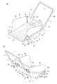
図1に於いて、1は公知のスノーダンプであり、該スノーダンプ1は、平面視略方形の底面板2の後辺に背面板3が延設して立設され、該底面板2の左右辺に、前端から後端に向かって高さが高くなるように上部が斜欠された左右側面板4,5が夫々延設して立設され、且つ、該背面板3の側端が該左右側面板4,5と連設されてスノーダンプ本体6が形成され、該スノーダンプ本体6に該スノーダンプ本体6を前方に押すための把手体7が固着されている。
Hereinafter, embodiments of the present invention will be described with reference to the drawings showing examples.
In FIG. 1, reference numeral 1 denotes a known snow dumper, and the snow dumper 1 is erected with a
そして、前記スノーダンプ本体6は合成樹脂板又は金属板等で一体に形成されており、該底面板2及び背面板3には補強のための複数のリブ2a,2a…、3a,3a…が形成されている。
The snow dump
又、前記把手体7は前記スノーダンプ本体6の左側面板4の外側面から前記背面板3の外側面及び右側面板5の外側面に延びて固着される取り付けパイプ8と、該取り付けパイプ8に連設され、且つ、該左右側面板4,5の後端から上方後方に延設される左右延設部9,10と、該左右延設部9,10の先端を相互に連結する把手部11とから成り、一方、前記背面板3の上端及び前記左右側面板4,5の上端には前記取り付けパイプ8を包持する止着縁部12,13,14が夫々形成されており、該取り付けパイプ8は、該背面板3の上端に形成された止着縁部12と、該左右側面板4,5の上端に形成された止着縁部13,14とに下方から嵌着した後、ビス(図示せず)等で止着されている。
The
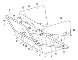
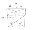
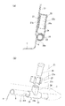
一方、同図に於いて21は、本発明のスノーダンプ用嵩上げ器具であり、該スノーダンプ用嵩上げ器具21は合成樹脂板、木板、或いは、金属板等で形成され、前記スノーダンプ1の背面板3上に立設して該背面板3の嵩上げをするための背面嵩上げ板22と、該背面嵩上げ板22に連結され、且つ、該スノーダンプ1の左右側面板4,5上に立設して該左右側面板4,5の嵩上げをするための左右側面嵩上げ板23,24とから成り、前記背面嵩上げ板22は正面視矩形状に形成され、且つ、該左右側面板4,5は下端部が後端から前端に向けて下方に向かって斜設され、即ち、後端から前端に向かって次第に嵩高が高くなるように形成され、図2に示すように、該スノーダンプ用嵩上げ器具21は前記スノーダンプ本体6に着脱自在に取り付けられるように構成され、該スノーダンプ用嵩上げ器具21が該スノーダンプ本体6に取り付けられた時、該スノーダンプ用嵩上げ器具21の上端の高さは略水平になるように構成されている。
On the other hand, in the figure,
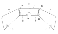
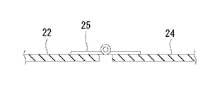
そして、前記背面嵩上げ板22と前記左右側面嵩上げ板23,24とは図3及び図4に示す蝶番25,25…によって図5に示す如く折り畳み自在に連結されていると共に、該背面嵩上げ板22には作業時に操作者が背面板3の上端への足掛けが可能となるように、該背面嵩上げ板22の下部中央が切欠されて足掛け用切欠き22aが形成されている。
The
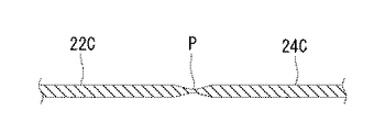
尚、前記背面嵩上げ板22と前記左右側面嵩上げ板23,24とを蝶番25,25で連結する構成に変えて、例えば、図6に示す如く、背面嵩上げ板22Cと左右側面嵩上げ板24C,24Cとを硬質性樹脂によって一体に成型し、該背面嵩上げ板22Cと左右側面嵩上げ板24C,24Cの隣接部Pを薄肉状に形成して折り畳み自在に構成することも可能であり、然る時は、前述の構成と同様の効果が期待できると共に、該背面嵩上げ板22と左右側面嵩上げ板24C,24Cとを一体に成型するため製作が容易になり、且つ、部品点数を少なくすることができる利点がある。
For example, as shown in FIG. 6, the
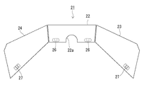
更に、図7に示す如く、前記背面嵩上げ板22の外側面左右下部に該背面嵩上げ板22を前記背面板3と連結するための2個の背面上部連結具26,26が固着されると共に、前記左右側面嵩上げ板23,24の外側面下部の前端近傍に該左右側面嵩上げ板23,24を前記左右側面板4,5と連結するための側面上部連結具27,27が固着されている。
Further, as shown in FIG. 7, two rear
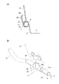
そして、図8に示す如く、前記背面上部連結具26は、断面略Ω字状に形成され、前記背面嵩上げ板22に固着されることにより断面略半円形状の嵌合孔26aが形成されるように構成されている。又、図9に示す如く、前記側面上部連結具27は、前記左右側面嵩上げ板23,24に固着させるための固着板27aと、連結ピン28を保持すべく断面C字状に形成された保持部27bとから形成され、該固着板27aに該保持部27bが固着されている。尚、該固着板27aと保持部27bとは一体に成型されても良い。そして、然る時も同様な効果が期待できる。
As shown in FIG. 8, the back
一方、図2に示す如く、前記取り付けパイプ8及び該取り付けパイプ8を止着する止着縁部12に前記背面嵩上げ板22を取り付けるための2個の背面下部連結具29,29が前記背面上部連結具26,26に対応する位置に着脱自在に固着されると共に、前記取り付けパイプ8及び該取り付けパイプ8を止着する止着縁部13,14に前記左右側面嵩上げ板23,24を取り付けるための側面下部連結具30,30が前記側面上部連結具27,27に着脱自在に固着される。
On the other hand, as shown in FIG. 2, the two rear
そして、前記背面下部連結具29は図8に示す如く、断面C字状に形成された下部体31に同様に断面C字状に形成された凸部32がT字状に接合されており、該下部体31の切欠部31aを拡開して該下部体31を前記取り付けパイプ8及び前記止着縁部12に嵌合させ、該凸部32を前記背面上部連結具26の嵌合孔26aに嵌合させるように構成されている。尚、前記背面下部連結具29は前記下部体31と凸部32とが一体に成型されても良い。そして、然る時も同様な効果が期待できる。
As shown in FIG. 8, the rear
又、前記側面下部連結具30は図9に示す如く、断面C字状に形成された下部体33に断面円形状に形成された突出体34がT字状に接合されており、該下部体33の切欠部33aを拡開して該下部体33を前記取り付けパイプ8及び前記止着縁部13,14に嵌合させるように構成されており、該突出体34を前記連結ピン28を介して前記背面上部連結具26に連結するように構成されている。尚、前記側面下部連結具30は前記下部体33と突出体34とが一体に成型されても良い。そして、然る時も同様な効果が期待できる。
Further, as shown in FIG. 9, the side
而して、前記スノーダンプ用嵩上げ器具21を前記スノーダンプ1に取り付ける場合について説明すると、先ず、前記背面下部連結具29,29を構成する下部体31,31の切欠部31a,31aを拡開し、該下部体31,31を前記取り付けパイプ8及び前記止着縁部12に嵌合させて該背面下部連結具29,29を取り付け、同様に、前記左右の側面下部連結具30,30を構成する下部体33,33の切欠部33a,33aを拡開し該下部体33,33を前記取り付けパイプ8及び前記止着縁部13,14に夫々嵌合させて、該左右の側面下部連結具30,30を取り付ける。
Thus, the case where the snow dumping raising
次に、前記蝶番25,25…によって前記スノーダンプ用嵩上げ器具21の前記背面嵩上げ板22と前記左右側面嵩上げ板23,24とを略平面視コ字状に開いた後、該スノーダンプ用嵩上げ器具21の前記背面上部連結具26,26の嵌合孔26a,26aに前記背面下部連結具29,29の凸部32,32を嵌合させ、更に、前記左右の側面上部連結具27,27の保持部27b,27bを前記側面下部連結具30,30の突出体34,34上に位置合わせして前記連結ピン28,28を該保持部27b,27bと該突出体34,34の穴34a,34a内に挿入して該側面上部連結具27,27と側面下部連結具30,30とを夫々相互に連結すると、前記スノーダンプ用嵩上げ器具21は前記スノーダンプ1に取り付けられる。
Next, after opening the
そして、該スノーダンプ用嵩上げ器具21を取り付けたスノーダンプ1を使用する場合は、前記把手部11を押し、該スノーダンプ1を前進させて雪を掬い、或いは、該把手部11を押すだけでは前進が困難な場合は、該把手部11を把持した状態で前記足掛け用切欠き22a内に足を入れ、前記背面板3上端の前記止着縁部12に足を掛け、足で該背面板3を前方に押すことによりスノーダンプ1を前進させて雪を掬うことができる。そして、掬った雪は該スノーダンプ1を所望の場所に移動させて排雪する。
When using the snow dumper 1 with the snow dumping raising
又、前記スノーダンプ用嵩上げ器具21を前記スノーダンプ1から取り外す場合は、前記連結ピン28,28を取り外して前記左右の側面上部連結具27,27と前記左右の側面下部連結具30,30を切り離し、更に、前記背面上部連結具26,26が形成する嵌合孔26a,26aから前記背面下部連結具29,29の凸部32,32を抜き取り、該背面下部連結具29,29と該背面上部連結具26,26とを切り離せば、前記スノーダンプ用嵩上げ器具21は取り外され、前記蝶番25,25…を介して前記左右側面嵩上げ板23,24を折り畳めば、該スノーダンプ用嵩上げ器具21は収納状態になる。
Further, when removing the snow dumping raising
斯くして、前記スノーダンプ用嵩上げ器具21はスノーダンプ1に着脱自在に取り付けて多量の雪を掬い上げ排雪出来るため、多量の排雪作業を行う場合に於いて、作業効率が良く、作業時間を短縮できると共に、該スノーダンプ用嵩上げ器具21の着脱及び収納も容易であり、少ない雪を排雪する場合は該スノーダンプ用嵩上げ器具21を取り外して作業を行える。
Thus, the snow dumping raising
又、前記背面嵩上げ板22と前記左右側面嵩上げ板23,24とは蝶番25,25…によって折り畳み自在に連結されているのでスノーダンプ用嵩上げ器具21の収納が容易になる。
Further, since the
更に、前記背面下部連結具29は上方に突出する凸部32を備え、前記背面上部連結具26は該凸部32を嵌合させる嵌合孔26aを備えているので、該凸部32を該嵌合孔26aに嵌入させることにより、連結が容易になると共に、取り外しも容易となる。
Further, the
更に又、前記側面下部連結具30は上方に突出する突出体34を備え、且つ、該突出体34の上部には上方に開放する穴34aが形成されており、一方、前記側面上部連結具27は連結ピン28を保持するための保持部27bを備えているので、該連結ピン28によって前記側面下部連結具30と側面上部連結具27とを容易に連結することが出来、該連結ピン28を外すことにより、該側面下部連結具30と側面上部連結具27とを容易に取り外すことができる。
Further, the
そして、前記背面嵩上げ板22は、中央下部が切欠されて足掛け用切欠き22aが形成されているので、前記背面板3の上端に足を掛けて足の力でスノーダンプ1を前方に押すことが可能となり、多量の雪を掬う作業、又は、硬くなった雪を掬う作業が容易になる。
The
1 スノーダンプ
2 底面板
3 背面板
4 左側面板
5 右側面板
6 スノーダンプ本体
7 把手体
8 取り付けパイプ
9 左延設部
10 右延設部
11 把手部
12,13,14 止着縁部
21 スノーダンプ用嵩上げ器具
22 背面嵩上げ板
23 左側面嵩上げ板
24 右側面嵩上げ板
25 蝶番
26 背面上部連結具
26a 嵌合孔
27 側面上部連結具
27b 保持部
28 連結ピン
29 背面下部連結具
30 側面下部連結具
32 凸部
34 突出体
34a 穴
P 隣接部
DESCRIPTION OF SYMBOLS 1
Claims (7)
The said back raising board is notched in the center lower part, It is comprised so that an operator can put a foot on the upper end of the said back board during work | work. Or the raising tool for snow dumping of 6.
Priority Applications (1)
| Application Number | Priority Date | Filing Date | Title |
|---|---|---|---|
| JP2004106394A JP3862710B2 (en) | 2004-03-31 | 2004-03-31 | Snow dumping raising device |
Applications Claiming Priority (1)
| Application Number | Priority Date | Filing Date | Title |
|---|---|---|---|
| JP2004106394A JP3862710B2 (en) | 2004-03-31 | 2004-03-31 | Snow dumping raising device |
Publications (2)
| Publication Number | Publication Date |
|---|---|
| JP2005290800A true JP2005290800A (en) | 2005-10-20 |
| JP3862710B2 JP3862710B2 (en) | 2006-12-27 |
Family
ID=35324049
Family Applications (1)
| Application Number | Title | Priority Date | Filing Date |
|---|---|---|---|
| JP2004106394A Expired - Fee Related JP3862710B2 (en) | 2004-03-31 | 2004-03-31 | Snow dumping raising device |
Country Status (1)
| Country | Link |
|---|---|
| JP (1) | JP3862710B2 (en) |
Cited By (6)
| Publication number | Priority date | Publication date | Assignee | Title |
|---|---|---|---|---|
| KR100764150B1 (en) | 2007-01-25 | 2007-10-05 | 양수영 | Prefabricated shovel |
| JP2012046920A (en) * | 2010-08-25 | 2012-03-08 | Toshiharu Ueji | Improved sleigh with grip for doubling carrying amount of snow by attaching auxiliary board and support rod to sleigh with grip |
| JP2013217178A (en) * | 2012-04-11 | 2013-10-24 | Tsugihiro Matsui | Detachable connected snow removal tool |
| JP2014020100A (en) * | 2012-07-18 | 2014-02-03 | Yaeko Toyokura | Snow removal tool capable of adjusting amount of snow to be loaded |
| JP2015094166A (en) * | 2013-11-13 | 2015-05-18 | 有限会社 佐藤住研 | Snow overflowing prevention tool attached to pushing conveyance type snow removing tool and fixture for attaching snow overflowing prevention plate in pushing conveyance type snow removing tool |
| KR20170040626A (en) * | 2015-10-05 | 2017-04-13 | 송재훈 | snow shovel with fixing clamp |
-
2004
- 2004-03-31 JP JP2004106394A patent/JP3862710B2/en not_active Expired - Fee Related
Cited By (7)
| Publication number | Priority date | Publication date | Assignee | Title |
|---|---|---|---|---|
| KR100764150B1 (en) | 2007-01-25 | 2007-10-05 | 양수영 | Prefabricated shovel |
| JP2012046920A (en) * | 2010-08-25 | 2012-03-08 | Toshiharu Ueji | Improved sleigh with grip for doubling carrying amount of snow by attaching auxiliary board and support rod to sleigh with grip |
| JP2013217178A (en) * | 2012-04-11 | 2013-10-24 | Tsugihiro Matsui | Detachable connected snow removal tool |
| JP2014020100A (en) * | 2012-07-18 | 2014-02-03 | Yaeko Toyokura | Snow removal tool capable of adjusting amount of snow to be loaded |
| JP2015094166A (en) * | 2013-11-13 | 2015-05-18 | 有限会社 佐藤住研 | Snow overflowing prevention tool attached to pushing conveyance type snow removing tool and fixture for attaching snow overflowing prevention plate in pushing conveyance type snow removing tool |
| KR20170040626A (en) * | 2015-10-05 | 2017-04-13 | 송재훈 | snow shovel with fixing clamp |
| KR101896988B1 (en) * | 2015-10-05 | 2018-09-11 | 송재훈 | snow shovel with fixing clamp |
Also Published As
| Publication number | Publication date |
|---|---|
| JP3862710B2 (en) | 2006-12-27 |
Similar Documents
| Publication | Publication Date | Title |
|---|---|---|
| US6824180B2 (en) | Quick connect tool | |
| US20050001439A1 (en) | Device for removing or inserting a fuse | |
| GB2365061A (en) | Pin and grommet arrangement for component attachment having release by rotation | |
| PL1929103T3 (en) | A joint for panels. | |
| JP2005290800A (en) | Raising implement for snow dump | |
| JP2002045255A (en) | Connecting implement | |
| JP2007210343A (en) | Binder | |
| JP3664078B2 (en) | Binding base fixing structure | |
| JP5934876B2 (en) | Detachable snow shovel | |
| JP2006169934A (en) | Snow removing tool and snow removing auxiliary tool | |
| JP2006342615A (en) | Scaffolding unit and scaffold-forming tool | |
| JP2005207010A (en) | Floor board | |
| KR200250963Y1 (en) | A rivet | |
| JP2003276375A (en) | Binder | |
| JP4274757B2 (en) | Unit device housing | |
| JP3081845B1 (en) | Substrate holder | |
| JP3122144U (en) | Trowel | |
| JP2003171079A (en) | Moving handrail attaching/detaching tool for passenger conveyer | |
| JP2007177442A (en) | Scoop auxiliary tool | |
| JPS6140077Y2 (en) | ||
| JP4725340B2 (en) | Bathroom wall panel connection structure | |
| JP3034548U (en) | Snow removal equipment | |
| JP6821143B2 (en) | Auxiliary member for toilet bowl construction | |
| JP3026853U (en) | Snow dump | |
| JP3113731U (en) | Foot switch holder |
Legal Events
| Date | Code | Title | Description |
|---|---|---|---|
| A977 | Report on retrieval |
Effective date: 20060607 Free format text: JAPANESE INTERMEDIATE CODE: A971007 |
|
| A131 | Notification of reasons for refusal |
Effective date: 20060620 Free format text: JAPANESE INTERMEDIATE CODE: A131 |
|
| A521 | Written amendment |
Effective date: 20060804 Free format text: JAPANESE INTERMEDIATE CODE: A523 |
|
| TRDD | Decision of grant or rejection written | ||
| A01 | Written decision to grant a patent or to grant a registration (utility model) |
Free format text: JAPANESE INTERMEDIATE CODE: A01 Effective date: 20060912 |
|
| A61 | First payment of annual fees (during grant procedure) |
Free format text: JAPANESE INTERMEDIATE CODE: A61 Effective date: 20060926 |
|
| R150 | Certificate of patent (=grant) or registration of utility model |
Free format text: JAPANESE INTERMEDIATE CODE: R150 |
|
| FPAY | Renewal fee payment (prs date is renewal date of database) |
Free format text: PAYMENT UNTIL: 20091006 Year of fee payment: 3 |
|
| FPAY | Renewal fee payment (prs date is renewal date of database) |
Free format text: PAYMENT UNTIL: 20101006 Year of fee payment: 4 |
|
| FPAY | Renewal fee payment (prs date is renewal date of database) |
Year of fee payment: 5 Free format text: PAYMENT UNTIL: 20111006 |
|
| LAPS | Cancellation because of no payment of annual fees |