JP2005290786A - Hanging fixture - Google Patents
Hanging fixture Download PDFInfo
- Publication number
- JP2005290786A JP2005290786A JP2004106086A JP2004106086A JP2005290786A JP 2005290786 A JP2005290786 A JP 2005290786A JP 2004106086 A JP2004106086 A JP 2004106086A JP 2004106086 A JP2004106086 A JP 2004106086A JP 2005290786 A JP2005290786 A JP 2005290786A
- Authority
- JP
- Japan
- Prior art keywords
- steel column
- hanging jig
- jig
- main body
- engaging
- Prior art date
- Legal status (The legal status is an assumption and is not a legal conclusion. Google has not performed a legal analysis and makes no representation as to the accuracy of the status listed.)
- Granted
Links
Images

Landscapes
- Conveying And Assembling Of Building Elements In Situ (AREA)
- Load-Engaging Elements For Cranes (AREA)
Abstract
Description
本発明は建築用の鉄骨柱を立設させるための吊り治具に関し、特に鉄骨柱への取り付けが容易で且つ鉄骨柱を確実に保持することが可能な吊り治具に関する。 The present invention relates to a hanging jig for standing a steel column for construction, and more particularly to a hanging jig that can be easily attached to a steel column and can reliably hold the steel column.
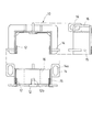
住宅等の建物において、躯体に鉄骨を使用した構造が知られている。建築現場等における鉄骨柱の建方は、従来では、例えば図7及び図8に示す吊り治具を用いて行われていた。
図7及び図8に示す吊り治具100は、柱頭係合部101と、ロープ102と、ロープ102に取着された取付具103とを備えて構成されている。ロープは柱頭係合部101に合計4本が接続されており、このうち2本はクレーンのフック掛け105に連結されている。他の2本のロープ102の先端には、取付具103が取着され、この取付具103が鉄骨柱106に設けられた作業用梯子の係合具107に取着されるように構成されている。
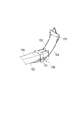
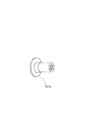
鉄骨柱に設けられた係合具107とは、図8に示すような円筒形状をしている。この係合具107は、鉄骨柱に作業用の梯子を取り付けるために設けられているものである。
作業用の梯子は、鉄骨柱が立設・固定された後に、鉄骨柱106の係合具107に引っ掛けられて取り付けられる。この梯子は、鉄骨柱106の立設後に、吊り治具100を取り外す等の各種作業に用いられるものである。
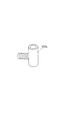
係合具107は、図9に示すような部材107aからなる。この部材107aは、鉄骨柱106に固着されたねじ穴部材107bに取着されている。ねじ穴部材107bの形状を図10に示す。このねじ穴部材107bは、鉄骨柱106に穿設された孔に嵌着されている。
鉄骨柱106を立設するときは、取付具103を鉄骨柱106の係合具107に取り付ける。取付具103が係合具107に取り付けられた状態を図11に示す。
このように、取付具103のコ字形のフック103aを、係合具107を上下方向から挟み込むように取り付ける。そして、フック103aと係合具107を貫通してボルト103bを配設する。このようにして、吊り治具100の取付具103が、鉄骨柱106の係合具107において固定される。
このようにして、鉄骨柱106に吊り治具100が固定されたら、フック掛け105をクレーンのフックに接続し、クレーンで引き上げる。こうすることにより、鉄骨柱106は柱頭係合部101が取り付けられた側から持ち上げられ、最終的に垂直に立設される。
In a building such as a house, a structure using a steel frame as a frame is known. Conventionally, the construction of a steel column at a construction site or the like has been performed using, for example, a hanging jig shown in FIGS. 7 and 8.
The
The
The working ladder is attached by being hooked on the
The
When the
In this way, the U-shaped
In this way, when the
上記のように、従来の吊り治具100によれば、鉄骨柱106を立設させることが可能である。しかし、柱頭係合部101の上下側に複数本のロープ102を備えた構成とされているため、吊り治具100を取り扱う際にロープ102が絡まること等があり、取り扱いに手間がかかるという問題があった。
また、ロープ102の先端に設けられた取付具103を、それぞれ個々に鉄骨柱106の係合具107に取り付ける構成であるため、この取り付けに手間がかかるという問題があった。
上記問題を解決するために、鉄骨柱への取り付けを容易に行うことが可能な鉄骨柱の吊り治具が提案されている(例えば、特許文献1参照)。
In addition, since the
In order to solve the above problem, a steel column suspension jig that can be easily attached to a steel column has been proposed (see, for example, Patent Document 1).
上記特許文献1に開示された吊り治具は、略コの字状の第1部材12aと、枢支ピン13a周りで揺動開閉自在に枢着された第2部材とを備え、構真柱Bを立設するときは、これら第1、第2部材12a,12bを構真柱Bに係合させる。
そして、第2部12bを枢支ピン13aで固定した後、クレーンで吊り治具を引き上げる。吊り治具は、構真柱Bに設けられた接合プレート2に係合して固定され、構真柱Bは引き上げられて垂直に立設される。
特許文献1に開示された吊り治具は、吊り治具で構真柱Bを吊り上げるとき、吊り治具は構真柱Bに設けられた接合プレート2に引っ掛けられて固定されているだけであるため、より確実に吊り治具を固定できる構成であれば好ましい。
また、特許文献1に開示された吊り治具は、構真柱Bに吊り治具を取り付けるときに、第2部12bを開閉するために、枢支ピン13aを抜き差しする必要があり、取り付けに手間がかかるという不都合があった。
本発明の目的は、鉄骨柱への取り付けが容易であり、且つ鉄骨柱を確実に保持して立設させることが可能な、鉄骨柱の吊り治具を提供することにある。
The suspension jig disclosed in Patent Document 1 includes a substantially U-shaped
And after fixing the
In the suspension jig disclosed in Patent Document 1, when the construction pillar B is lifted by the suspension jig, the suspension jig is only hooked and fixed to the joining plate 2 provided on the construction pillar B. For this reason, any configuration that can fix the suspension jig more reliably is preferable.
In addition, the suspension jig disclosed in Patent Document 1 requires that the pivot pin 13a be inserted and removed in order to open and close the
An object of the present invention is to provide a steel column suspension jig that can be easily attached to a steel column and can be held upright while being securely held.
前記課題は、請求項1に係る鉄骨柱の吊り治具によれば、吊り上げ装置に連結されて建築用の鉄骨柱を懸吊する吊り治具であって、前記鉄骨柱の外周部には、作業用の梯子を取り付けるための、中空部を有する係合部が設けられ、該吊り治具は、前記鉄骨柱に三方から係合可能な略コ字形の本体部と、該本体部に設けられ、前記吊り上げ装置との連結部材が配設される連結部材配設部と、前記本体部の内壁面に設けられ、前記鉄骨柱の係合部に、前記鉄骨柱の基部側から頂部側に向けて差し込まれる係合片とを備えたことにより解決される。
本発明の吊り治具によれば、鉄骨柱に嵌合可能な本体部の内壁側に、鉄骨柱に梯子を取り付けるために設けられた係合部に係合可能な係止片を備えており、この係止片が梯子用の係合部に差し込まれることにより、鉄骨柱に固定される。
そして、本体部には連結部材としてのロープが接続され、このロープが吊り上げ装置への接続部材であるフック掛けに接続され、フック掛けがクレーンにより引き上げられることにより、鉄骨柱を立設することができる。
According to the steel column suspension jig according to claim 1, the subject is a suspension jig that is connected to a lifting device and suspends a steel column for construction, and the outer periphery of the steel column includes: An engagement portion having a hollow portion is provided for attaching a work ladder, and the hanging jig is provided on the main body portion and a substantially U-shaped main body portion that can be engaged with the steel column from three sides. A connecting member disposing portion where a connecting member to the lifting device is disposed, and an inner wall surface of the main body, and the engaging portion of the steel column is directed from the base side to the top side of the steel column This is solved by providing an engaging piece to be inserted.
According to the hanging jig of the present invention, the inner wall side of the main body portion that can be fitted to the steel column is provided with a locking piece that can be engaged with an engaging portion that is provided to attach a ladder to the steel column. This locking piece is fixed to the steel column by being inserted into the engaging portion for the ladder.
And a rope as a connecting member is connected to the main body, and this rope is connected to a hook hook that is a connecting member to the lifting device, and the hook hook is pulled up by a crane, so that the steel column can be erected. it can.
なお、前記本体部に、前記鉄骨柱に圧接されるねじ部材が設けられていると、このねじ部材により、吊り治具を鉄骨柱により確実に固定することができ好適である。
このとき、前記係合片にも、前記ねじ部材を螺合可能な孔が設けられた構成とすると、ねじ部材が2箇所で保持されることになり、ねじ部材の安定性を保つことができ好適である。
さらに、前記本体部には把持部が設けられていると、吊り治具を取り付けたり或いは取り外すときに、この把持部を持って作業を行うことができ、作業効率の向上を図ることが可能となる。
In addition, it is preferable that the main body portion is provided with a screw member that is pressed against the steel column so that the suspension jig can be reliably fixed to the steel column by the screw member.
At this time, if the engagement piece is also provided with a hole through which the screw member can be screwed, the screw member is held at two locations, and the stability of the screw member can be maintained. Is preferred.
Furthermore, when the main body portion is provided with a gripping portion, when the hanging jig is attached or detached, it is possible to work by holding this gripping portion, and it is possible to improve work efficiency. Become.
以上のように、本発明の吊り治具によれば、中空部を備えた鉄骨柱の梯子用係合部を利用して、この梯子用係合部に係合片を差し込むことにより、鉄骨柱に吊り治具を取り付けるように構成されているので、簡単な構成で、効率良く鉄骨柱を立設させることが可能となる。
また、係合片を梯子用係合部に差し込むように構成されているので、この係合片を介して吊り治具が鉄骨柱に確実に固定され、鉄骨柱の引き上げを安定して行うことが可能となる。
As described above, according to the suspension jig of the present invention, by using the ladder engaging portion of the steel column provided with the hollow portion, by inserting the engaging piece into the ladder engaging portion, Since the suspension jig is attached to the steel frame, the steel column can be efficiently erected with a simple configuration.
In addition, since the engaging piece is configured to be inserted into the ladder engaging portion, the hanging jig is securely fixed to the steel column via the engaging piece, and the steel column can be stably pulled up. Is possible.
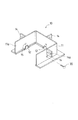
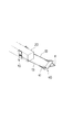
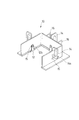
以下、本発明の一実施形態について、図を参照して説明する。なお、以下に説明する部材、配置等は、本発明を限定するものではなく、本発明の趣旨に沿って各種改変することができることは勿論である。図1及び図2は本実施形態に係る吊り治具を示す説明図、図3は鉄骨柱の断面図、図4は吊り治具の使用状態を示す説明図である。 Hereinafter, an embodiment of the present invention will be described with reference to the drawings. It should be noted that members, arrangements, and the like described below do not limit the present invention, and it goes without saying that various modifications can be made in accordance with the spirit of the present invention. 1 and 2 are explanatory views showing a hanging jig according to the present embodiment, FIG. 3 is a sectional view of a steel column, and FIG. 4 is an explanatory view showing a usage state of the hanging jig.
本発明は、建物の躯体に使用される鉄骨柱を、横倒しに仮置きさせた状態から、立設させた状態にするために用いられる吊り治具10に関するものである。
本例の吊り治具10により立設される鉄骨柱20は、図3に示すように、断面矩形の鉄骨柱であり、本体21の外周面22に、作業用の梯子を係合する係合具23が設けられている。
係合具23は、従来例で示したものと異なり、屈曲した板状部材を、溶接等により本体21の外周面22に取り付けることにより形成されている。板状部材は、鉄骨柱20の上下方向に、所定間隔で設けられている。
係合具23と、鉄骨柱20の外周面22との間には、隙間24が形成されている。この隙間24が、梯子との係合部として使用される。
作業中に梯子を使用する場合は、この隙間24のうち2つに、梯子の端部を引っ掛けて使用する。
梯子との係合部を設けるための係合具23が上記構成とされていることにより、従来例で示した鉄骨柱のように、鉄骨柱20に係合具を取り付けるための孔を設ける必要がなくなる。鉄骨柱に孔を設ける作業には手間がかかるため、本例で示される鉄骨柱20のような係合具23を用いることが望ましい。また、本例の係合具23によれば、鉄骨柱20に孔を設ける必要がないため、鉄骨柱20のより高い強度を得ることができ好適である。
本例の鉄骨柱20は、上記梯子用の係合部、すなわち隙間24が、外周面に三箇所形成されている。なお、梯子用の係合部は、三箇所ではなく四箇所設けられていても良い。
The present invention relates to a
As shown in FIG. 3, the
Unlike the conventional example, the
A
When a ladder is used during work, the end of the ladder is hooked on two of the
Since the
In the
吊り治具10は、鉄骨柱20に三方から係合する略コ字形の本体部11と、この本体部11の内壁に設けられた係合片12と、連結部材としてのロープ13が接続される、ロープ接続部14とを備えている。このロープ接続部14が、請求の範囲における連結部材配設部に相当するものである。
本体部11は、鉄骨柱20の係合具23が設けられている箇所に嵌合可能な大きさに形成されている。
本体部11の内壁面11aには、吊り治具10を鉄骨柱20に取り付けたときに、鉄骨柱20の梯子用の係合部(隙間24)に差し込まれる係合片12が設けられている。係合片12は本体部11の各内壁面11aにそれぞれ設けられている。吊り治具10が鉄骨柱20に取り付けられたとき、この係合片12の前側表面が、鉄骨柱20の表面に当接する。
係合片12と、鉄骨柱20の係合具23とは略同じ高さに形成されている。係合片12は内壁面11aとの間に所定の隙間12aが空くようにして配設されている。
隙間12aは、鉄骨柱20の梯子用の係合具23の厚さと同一か或いは若干大きめに形成されている。
これは、鉄骨柱20に吊り治具10を取り付けたとき、吊り治具10の係合片12が、鉄骨柱20の係合具23の隙間24に差し込まれるためである。係合片12に、上記隙間12aが形成されていることにより、係合片12が隙間24に差し込まれたときに、係合片12と本体部11の内壁面11aとで、係合具23を挟持することが可能となる。
さらに、吊り治具10の本体部11には、係合片12の上方位置に孔15が設けられている。この孔15にはねじ部材30が螺合される。このねじ部材30は、後述するように、吊り治具10側から柱部材20を押圧し、吊り治具10を鉄骨柱20に対して強固に固定するためのものである。
ロープ接続部14は、本体部11の各外側面に設けられている。ロープ接続部14は、外側面から突出して設けられており、ロープ13を挿通可能な孔14aが形成されている。
このロープ接続部に取り付けられるロープ13は、フック掛け40に接続される。フック掛け40は、吊り上げ装置としてのクレーン(図示せず)のフックに接続される。
The hanging
The main body 11 is formed in a size that can be fitted into a place where the engaging
The
The
The
This is because when the
Further, a
The
The
図4に、吊り治具10の使用状態を示す。図4に示すように、吊り治具10は、横倒し状態に仮置きされた鉄骨柱20に取り付けられる。吊り治具10は、鉄骨柱20が立設されたときに上方になる端部側に取り付けられる。吊り治具10は、先ず、鉄骨柱20の梯子取付用の係合具23が設けられていない箇所に嵌合される。吊り治具10は、係合片12の先端が、係合具23側を向くように、鉄骨柱20に嵌合される。
次に、吊り治具10を鉄骨柱20に固定する。このとき、吊り治具10を鉄骨柱20の頂部側へ向けてスライドさせ、吊り治具10の係合片12を、鉄骨柱20の係合具23の隙間24に差し込む。このようにして、吊り治具10が鉄骨柱20に取付及び固定される。
さらに、吊り治具10の孔15にそれぞれねじ部材30を螺合させ、鉄骨柱20に向けてねじ部材30を締め込む。このようにして、吊り治具10が鉄骨柱20に確実に固定される。このとき、3本のねじ部材30を締め込むことにより、このねじ部材30を介して吊り治具10が鉄骨柱20に強固に固定される。
次いで、吊り治具10と、クレーンのフック掛け40をロープ13で接続する。このとき、ロープ13の先端部が輪状に形成されていると、フック掛け40の係合部41に簡単に取り付けることができ好適である。
吊り治具10とフック掛け40がロープ13で接続されたら、フック掛け40をクレーンのフックに取り付ける。そして、クレーンを作動させ、フック掛け40を吊り上げる。
フック掛け40が吊り上げられると、フック掛け40に接続された吊り治具10、及び吊り治具10に接続された鉄骨柱20が吊り上げられる。吊り治具10は、鉄骨柱20の頂部側に配設されているので、鉄骨柱20は頂部側から吊り上げられ、徐々に立ち上がる。鉄骨柱20が立設するまで、クレーンでの引き上げを行う。鉄骨柱20が立設されたら、鉄骨柱20を固定し、吊り治具10を撤去する。
FIG. 4 shows the usage state of the hanging
Next, the hanging
Further, the
Next, the hanging
When the hanging
When the
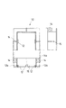
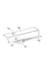
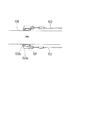
図5及び図6は、他の実施例に係る吊り治具10を示す説明図である。本例において、前記実施例と同一部材には、同一符号を付してその説明を省略する。
図5及び図6に示す吊り治具10は、前記実施例の吊り治具の係合片よりも、高さのある係合片12を備えている。そして、吊り治具10を固定するためのねじ部材30の挿通孔15が、吊り治具10の壁面だけでなく、係合片12にも、孔12bとして設けられている。
このような構成により、ねじ部材30が2箇所の孔15,12bを貫通する構成とすることになり、ねじ部材30を締め込んだときに、ねじ部材30を適切な位置でずれないように確実に保持することが可能となる。
また、本実施例に係る吊り治具10は、ロープ接続部14が、本体部11の上方に突出して設けられている。そして、前記実施例よりも大きめの孔14aが形成されている。ロープ接続部14をこのような構成とすることにより、より簡単にロープ13を配設することが可能となる。
さらに、本実施例に係る吊り治具10は、把持部16を備えている。把持部16が設けられていることにより、吊り治具10を鉄骨柱20へ取り付けたり或いは取り外したりするときに、この把持部16を持って行うことができ、作業効率を向上させることが可能となる。
5 and 6 are explanatory views showing a hanging
The
With such a configuration, the
Further, in the hanging
Furthermore, the hanging
10 吊り治具、 11 本体部、 12 係合片、 12a 隙間、 13 ロープ、 14 ロープ接続部、 15 孔、 16 把持部、 20 鉄骨柱、 21 本体、 22 外周面、 23 係合具、 24 隙間、 30 ねじ部材、 40 フック掛け、 41 係合部
DESCRIPTION OF
Claims (4)
前記鉄骨柱の外周部には、作業用の梯子を取り付けるための、中空部を有する係合部が設けられ、
該吊り治具は、前記鉄骨柱に三方から係合可能な略コ字形の本体部と、
該本体部に設けられ、前記吊り上げ装置との連結部材が配設される連結部材配設部と、
前記本体部の内壁面に設けられ、前記鉄骨柱の係合部に、前記鉄骨柱の基部側から頂部側に向けて差し込まれる係合片とを備えたことを特徴とする吊り治具。 A hanging jig that is connected to a lifting device and suspends a steel column for construction,
The outer periphery of the steel column is provided with an engaging portion having a hollow portion for attaching a working ladder,
The hanging jig is a substantially U-shaped main body that can be engaged with the steel column from three sides,
A connecting member disposition portion provided in the main body portion and disposing a connecting member with the lifting device;
A hanging jig comprising an engaging piece provided on an inner wall surface of the main body portion and inserted into an engaging portion of the steel column from a base side to a top side of the steel column.
Priority Applications (1)
| Application Number | Priority Date | Filing Date | Title |
|---|---|---|---|
| JP2004106086A JP4274991B2 (en) | 2004-03-31 | 2004-03-31 | Hanging jig |
Applications Claiming Priority (1)
| Application Number | Priority Date | Filing Date | Title |
|---|---|---|---|
| JP2004106086A JP4274991B2 (en) | 2004-03-31 | 2004-03-31 | Hanging jig |
Publications (2)
| Publication Number | Publication Date |
|---|---|
| JP2005290786A true JP2005290786A (en) | 2005-10-20 |
| JP4274991B2 JP4274991B2 (en) | 2009-06-10 |
Family
ID=35324035
Family Applications (1)
| Application Number | Title | Priority Date | Filing Date |
|---|---|---|---|
| JP2004106086A Expired - Fee Related JP4274991B2 (en) | 2004-03-31 | 2004-03-31 | Hanging jig |
Country Status (1)
| Country | Link |
|---|---|
| JP (1) | JP4274991B2 (en) |
Cited By (6)
| Publication number | Priority date | Publication date | Assignee | Title |
|---|---|---|---|---|
| CN102295228A (en) * | 2011-08-17 | 2011-12-28 | 天津市建工工程总承包有限公司 | Steel sling for steel column |
| CN102659017A (en) * | 2012-05-16 | 2012-09-12 | 威海建设集团股份有限公司 | Steel column hoisting system |
| JP2012193576A (en) * | 2011-03-17 | 2012-10-11 | Noriaki Nakamura | Hang-up tool for column member and hanging-up method |
| JP2020200601A (en) * | 2019-06-06 | 2020-12-17 | 大成建設株式会社 | Hoisting jig and method for disassembling steel tower |
| JP2021008722A (en) * | 2019-06-28 | 2021-01-28 | 大和ハウス工業株式会社 | Pillar suspension jig and wire fixture |
| JP2021055413A (en) * | 2019-09-30 | 2021-04-08 | 三和シヤッター工業株式会社 | Guide rail structure in building shutter device |
-
2004
- 2004-03-31 JP JP2004106086A patent/JP4274991B2/en not_active Expired - Fee Related
Cited By (9)
| Publication number | Priority date | Publication date | Assignee | Title |
|---|---|---|---|---|
| JP2012193576A (en) * | 2011-03-17 | 2012-10-11 | Noriaki Nakamura | Hang-up tool for column member and hanging-up method |
| CN102295228A (en) * | 2011-08-17 | 2011-12-28 | 天津市建工工程总承包有限公司 | Steel sling for steel column |
| CN102659017A (en) * | 2012-05-16 | 2012-09-12 | 威海建设集团股份有限公司 | Steel column hoisting system |
| JP2020200601A (en) * | 2019-06-06 | 2020-12-17 | 大成建設株式会社 | Hoisting jig and method for disassembling steel tower |
| JP7240959B2 (en) | 2019-06-06 | 2023-03-16 | 大成建設株式会社 | Hanging jig and steel tower dismantling method |
| JP2021008722A (en) * | 2019-06-28 | 2021-01-28 | 大和ハウス工業株式会社 | Pillar suspension jig and wire fixture |
| JP7249892B2 (en) | 2019-06-28 | 2023-03-31 | 大和ハウス工業株式会社 | Pole suspension jig and wire fixture |
| JP2021055413A (en) * | 2019-09-30 | 2021-04-08 | 三和シヤッター工業株式会社 | Guide rail structure in building shutter device |
| JP7359626B2 (en) | 2019-09-30 | 2023-10-11 | 三和シヤッター工業株式会社 | Guide rail structure in architectural shutter device |
Also Published As
| Publication number | Publication date |
|---|---|
| JP4274991B2 (en) | 2009-06-10 |
Similar Documents
| Publication | Publication Date | Title |
|---|---|---|
| JP4274991B2 (en) | Hanging jig | |
| JP2009135566A (en) | Installation structure of outdoor communication apparatus and installation method | |
| JP5356981B2 (en) | Scaffolding panel connector | |
| JP5225872B2 (en) | Hanging wire bracket | |
| JP6166870B2 (en) | Pillar standing method and pillar | |
| JP4243608B2 (en) | How to attach the brace | |
| JP7249892B2 (en) | Pole suspension jig and wire fixture | |
| JP2007022789A (en) | Suspension tool and vertical pipe construction method | |
| JP7477339B2 (en) | Pillar hanging jig | |
| JP6663726B2 (en) | Hanging bracket for hanging scaffold | |
| JP5988288B2 (en) | Jig for hanging long materials | |
| JP6223874B2 (en) | Lifting device and method of attaching and removing pole using the same | |
| JP2011106126A (en) | Working scaffold with supplementary panel | |
| JP4482752B2 (en) | Temporary enclosure mounting | |
| JPH1111854A (en) | Panel hang-up jig | |
| KR100777130B1 (en) | Joining structure of head frame for joining ceiling formwork panel frame | |
| JPH0829913B2 (en) | Lightweight cellular concrete panel lifting jig | |
| JP3136604U (en) | Temporary step for scaffolding | |
| JP2019196671A (en) | Hanging jig for column strut | |
| JP2024162640A (en) | PC steel lifting jig | |
| JP2007124720A (en) | Bracket angle adjuster and method of attaching bracket to a variety of utility poles | |
| JP2010133185A (en) | Hanging structure of soil retaining panel and sling | |
| JP4224584B2 (en) | Fastener for cable erection coil and method for fixing end of cable erection coil | |
| JP2024111916A (en) | Fixtures, lifting jigs, and installation methods | |
| JP2004162276A (en) | Unit lifting connection bracket |
Legal Events
| Date | Code | Title | Description |
|---|---|---|---|
| A621 | Written request for application examination |
Free format text: JAPANESE INTERMEDIATE CODE: A621 Effective date: 20070314 |
|
| A977 | Report on retrieval |
Free format text: JAPANESE INTERMEDIATE CODE: A971007 Effective date: 20090216 |
|
| TRDD | Decision of grant or rejection written | ||
| A01 | Written decision to grant a patent or to grant a registration (utility model) |
Free format text: JAPANESE INTERMEDIATE CODE: A01 Effective date: 20090224 |
|
| A01 | Written decision to grant a patent or to grant a registration (utility model) |
Free format text: JAPANESE INTERMEDIATE CODE: A01 |
|
| A61 | First payment of annual fees (during grant procedure) |
Free format text: JAPANESE INTERMEDIATE CODE: A61 Effective date: 20090303 |
|
| R150 | Certificate of patent (=grant) or registration of utility model |
Free format text: JAPANESE INTERMEDIATE CODE: R150 |
|
| FPAY | Renewal fee payment (prs date is renewal date of database) |
Free format text: PAYMENT UNTIL: 20120313 Year of fee payment: 3 |
|
| FPAY | Renewal fee payment (prs date is renewal date of database) |
Free format text: PAYMENT UNTIL: 20150313 Year of fee payment: 6 |
|
| LAPS | Cancellation because of no payment of annual fees |