JP2005290778A - Building structure - Google Patents
Building structure Download PDFInfo
- Publication number
- JP2005290778A JP2005290778A JP2004105893A JP2004105893A JP2005290778A JP 2005290778 A JP2005290778 A JP 2005290778A JP 2004105893 A JP2004105893 A JP 2004105893A JP 2004105893 A JP2004105893 A JP 2004105893A JP 2005290778 A JP2005290778 A JP 2005290778A
- Authority
- JP
- Japan
- Prior art keywords
- wall
- building
- internal wall
- materials
- heater
- Prior art date
- Legal status (The legal status is an assumption and is not a legal conclusion. Google has not performed a legal analysis and makes no representation as to the accuracy of the status listed.)
- Pending
Links
- 239000000463 material Substances 0.000 claims abstract description 51
- 239000011810 insulating material Substances 0.000 claims abstract description 14
- 239000011358 absorbing material Substances 0.000 claims abstract description 8
- RNFJDJUURJAICM-UHFFFAOYSA-N 2,2,4,4,6,6-hexaphenoxy-1,3,5-triaza-2$l^{5},4$l^{5},6$l^{5}-triphosphacyclohexa-1,3,5-triene Chemical compound N=1P(OC=2C=CC=CC=2)(OC=2C=CC=CC=2)=NP(OC=2C=CC=CC=2)(OC=2C=CC=CC=2)=NP=1(OC=1C=CC=CC=1)OC1=CC=CC=C1 RNFJDJUURJAICM-UHFFFAOYSA-N 0.000 claims description 9
- 239000003063 flame retardant Substances 0.000 claims description 9
- 238000009833 condensation Methods 0.000 abstract description 7
- 230000005494 condensation Effects 0.000 abstract description 7
- 238000005338 heat storage Methods 0.000 abstract description 7
- 230000007797 corrosion Effects 0.000 abstract 1
- 238000005260 corrosion Methods 0.000 abstract 1
- 230000000694 effects Effects 0.000 description 10
- 239000002023 wood Substances 0.000 description 6
- 238000003780 insertion Methods 0.000 description 5
- 230000037431 insertion Effects 0.000 description 5
- 239000011232 storage material Substances 0.000 description 4
- 238000010276 construction Methods 0.000 description 3
- 238000010438 heat treatment Methods 0.000 description 3
- 238000009413 insulation Methods 0.000 description 3
- 241000218645 Cedrus Species 0.000 description 2
- 239000004567 concrete Substances 0.000 description 2
- 238000001035 drying Methods 0.000 description 2
- 238000004519 manufacturing process Methods 0.000 description 2
- 230000002265 prevention Effects 0.000 description 2
- KDXKERNSBIXSRK-UHFFFAOYSA-N Lysine Natural products NCCCCC(N)C(O)=O KDXKERNSBIXSRK-UHFFFAOYSA-N 0.000 description 1
- 239000004472 Lysine Substances 0.000 description 1
- 239000004793 Polystyrene Substances 0.000 description 1
- 239000000853 adhesive Substances 0.000 description 1
- 230000001070 adhesive effect Effects 0.000 description 1
- 230000000903 blocking effect Effects 0.000 description 1
- 239000004566 building material Substances 0.000 description 1
- 239000011083 cement mortar Substances 0.000 description 1
- 238000001816 cooling Methods 0.000 description 1
- 230000005611 electricity Effects 0.000 description 1
- 239000011521 glass Substances 0.000 description 1
- 238000009434 installation Methods 0.000 description 1
- 238000000034 method Methods 0.000 description 1
- 239000004570 mortar (masonry) Substances 0.000 description 1
- 239000011120 plywood Substances 0.000 description 1
- 229920002223 polystyrene Polymers 0.000 description 1
- 239000004576 sand Substances 0.000 description 1
- 238000007790 scraping Methods 0.000 description 1
- 239000004575 stone Substances 0.000 description 1
- 239000010902 straw Substances 0.000 description 1
- 238000010792 warming Methods 0.000 description 1
- XLYOFNOQVPJJNP-UHFFFAOYSA-N water Substances O XLYOFNOQVPJJNP-UHFFFAOYSA-N 0.000 description 1
Images


Landscapes
- Load-Bearing And Curtain Walls (AREA)
Abstract
Description
本発明は、鉄骨住宅、木造住宅の住宅等、主として木造建物の建築構造に関するものである。 The present invention relates to an architectural structure of a wooden building, such as a steel-framed house or a wooden house.
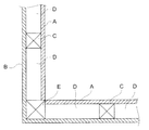
従来、戸建住宅等の建物の壁面構造は、図5に示すように、内壁Aと外壁Bとの間に間柱Cがあり、内壁Aと外壁Bとの間に内部空間Dがある構造となっていた。また、近年の住宅等の建物は、冷暖房効率を高めて省エネルギー化を実現するために、室内構造が高気密化、高断熱化されている。 Conventionally, as shown in FIG. 5, the wall surface structure of a building such as a detached house has a structure in which there is a stud C between the inner wall A and the outer wall B and an inner space D between the inner wall A and the outer wall B. It was. Further, in recent years, buildings such as houses have high air-tightness and high heat insulation in the indoor structure in order to improve energy efficiency by improving the cooling and heating efficiency.
しかし、前記図5に示す従来の壁面構造には、壁の外側の温度(外気温)と内側の温度(室内温度)との差が8℃以上あると、内部空間D内の空気が冷やされて内壁Aの外側に結露が発生し易くなり、年月の経過により内壁Aの周囲の土台や、柱Eや、間柱C等が腐食して建物の耐久性が低下するとか、水分が内壁Aの内面に染み出てその内面が汚れると同時に腐食するという課題がある。また、従来の壁面構造は、内部空間Dがあるため、強度や耐久性が十分ではないという課題もある。建物の壁は熱さ、寒さ、湿度、騒音等を遮断する役割も期待されている。 However, in the conventional wall structure shown in FIG. 5, if the difference between the outside temperature (outside temperature) and the inside temperature (room temperature) is 8 ° C. or more, the air in the internal space D is cooled. Condensation is likely to occur on the outside of the inner wall A, and the foundation around the inner wall A, the columns E, the intermediary columns C, etc. corrode over time, and the durability of the building is reduced. There is a problem that it oozes out on the inner surface of the glass and becomes corroded at the same time as the inner surface becomes dirty. Moreover, since the conventional wall surface structure has the internal space D, there also exists a subject that intensity | strength and durability are not enough. The walls of buildings are also expected to play a role in blocking heat, cold, humidity, noise, etc.
本発明は、上記課題を解決し、結露の発生を防ぐことができ、建物の強度や耐久性を高め、防熱、防寒、防湿、防騒音効果の優れた建築構造を提供するものである。 This invention solves the said subject, can prevent generation | occurrence | production of dew condensation, improves the intensity | strength and durability of a building, and provides the building structure excellent in the heat insulation, the cold prevention, moisture prevention, and the noise-proof effect.
本件出願の建築構造は、建物の柱に内壁の端部を組み合わせて内壁を取付け、内壁の外側に外壁を、内壁との間に空間を設けることなく直に取付けてある。この建築構造の内壁は複数本の角材又は板材を上下に又は横に配列したものとすることができる。前記建築構造において、外壁を、不燃材、難燃材、断熱材、防湿材、吸音材の一種又は二種以上を備えるものとすることができる。建物の基礎部分に加熱器を設けて蓄熱可能とすることもできる。 In the building structure of the present application, the inner wall is attached to the pillar of the building by combining the end of the inner wall, the outer wall is attached to the outside of the inner wall, and the outer wall is directly attached without providing a space between the inner wall and the inner wall. The inner wall of this building structure may be formed by arranging a plurality of square members or plate members vertically or horizontally. In the building structure, the outer wall may be provided with one or more of a non-combustible material, a flame retardant material, a heat insulating material, a moisture proof material, and a sound absorbing material. A heater can be installed at the base of the building to enable heat storage.
本件出願の建築構造は以下のような効果がある。
(1)内壁の外側に外壁を、内壁との間に空間を設けることなく直に取付けたので、内壁と外壁との間に空気が入り込むことがなく、内壁の外側に結露が発生しにくくなる。このため、内壁の周囲の土台、柱、内壁が腐食して建物の耐久性が低下することもない。
(2)建物の柱に内壁の端部を組み合わせて内壁を取付けるので、内壁と柱の結合が強固になり、強度に優れた建物となる。
The building structure of the present application has the following effects.
(1) Since the outer wall is directly attached to the outside of the inner wall without providing a space between the inner wall, air does not enter between the inner wall and the outer wall, and condensation hardly occurs on the outer side of the inner wall. . For this reason, the foundation, pillar, and inner wall around the inner wall are not corroded and the durability of the building is not lowered.
(2) Since the inner wall is attached by combining the end of the inner wall with the pillar of the building, the connection between the inner wall and the pillar becomes strong, and the building has excellent strength.
(3)内壁が複数本並べた20mm角以上の肉厚の角材を上下に又は横に配列したものであるため、数mm〜10mm程度の薄い板状の内壁に比して丈夫で強度が高く耐久性に優れ、肉厚であるため端部に突起を設けて柱へ組み付けることができ、柱との連結が容易且つ強固になる。また、結露防止の一助にもなる。このパネル状の部材は、壁材に限らず、床板、天井板等として用いることも可能である。
(4)また、内壁が複数本並べた20mm以上の肉厚の板材を上下に又は横に配列したものであるため、数mm〜10mm程度の薄い板状の内壁に比して丈夫で強度が高く耐久性に優れ、端部に突起を設けて柱へ組み付けることができ、柱との連結が容易且つ強固になる。また、結露防止の一助にもなる。このパネル状の部材は、壁材に限らず、床板、天井板等として用いることも可能である。
(5)内壁に角材又は板材を使用するため、間伐材や県産材の有効利用を図ることができる。
(6)内壁に連結具でパネル状に連結した角材又は板材を使用するため、間柱、筋交いが不要となるため、製作が容易であり、コストの低減も可能となる。
(3) Since the square walls with a thickness of 20 mm square or more with a plurality of inner walls are arranged vertically or horizontally, it is strong and strong compared to a thin plate-like inner wall of about several mm to 10 mm. Since it is excellent in durability and is thick, it can be provided with protrusions at the end portions and assembled to the pillar, and the connection with the pillar is easy and strong. It also helps prevent condensation. This panel-shaped member is not limited to a wall material, and can also be used as a floor board, a ceiling board, or the like.
(4) In addition, since a plurality of thick plate materials of 20 mm or more in which a plurality of inner walls are arranged are arranged vertically or horizontally, it is strong and strong compared to a thin plate-like inner wall of about several mm to 10 mm. It is highly durable and has a protrusion on the end and can be assembled to the column, and the connection with the column is easy and strong. It also helps prevent condensation. This panel-shaped member is not limited to a wall material, and can also be used as a floor board, a ceiling board, or the like.
(5) Since square wood or plate material is used for the inner wall, it is possible to make effective use of thinned wood and prefecture-produced wood.
(6) Since a square member or a plate member connected to the inner wall in the form of a panel with a connector is used, it is not necessary to form a stud or a brace, so that the manufacture is easy and the cost can be reduced.
外壁が、不燃材、難燃材、断熱材、防湿材、吸音材の一種又は二種以上を備えているので、前記効果に加えて、以下のような効果もある。
(7)不燃材や難燃材を使用すれば、万一、建物の内部で火災が発生しても隣接する部屋や別の建物に延焼しにくい。また、隣接する別の建物で発生した火災の飛び火を受けても火災になることがない。
(8)断熱材を使用すれば、建物の断熱効果が高まり、省エネルギー化が図られる。
(9)防湿材を使用すれば、外部の湿気の浸入を防止できるため、結露の発生がより一層防止される。
(10)吸音材を使用すれば、防音効果の高い建物となる。
(11)断熱材を使用し、その外側に不燃材或は難燃材を積層すれば、断熱材と不燃材或は難燃材の双方の効果が得られる。
(12)吸音材を使用し、その外側に不燃材或は難燃材を積層すれば、吸音材と不燃材或は難燃材の双方の効果が得られる。
Since the outer wall includes one or more of a non-combustible material, a flame retardant material, a heat insulating material, a moisture proof material, and a sound absorbing material, the following effects can be obtained in addition to the above effects.
(7) If a non-combustible material or a flame retardant material is used, even if a fire occurs inside the building, it is difficult to spread it to an adjacent room or another building. In addition, a fire does not occur even if a fire is generated in another adjacent building.
(8) If a heat insulating material is used, the heat insulation effect of a building will increase and energy saving will be achieved.
(9) If moisture-proof material is used, it is possible to prevent the intrusion of external moisture, thereby further preventing the occurrence of condensation.
(10) If a sound absorbing material is used, a building having a high soundproofing effect is obtained.
(11) If a heat insulating material is used and a non-combustible material or a flame retardant material is laminated on the outside thereof, the effects of both the heat insulating material and the non-combustible material or the flame retardant material can be obtained.
(12) If a sound absorbing material is used and a non-combustible material or a flame retardant material is laminated on the outside, effects of both the sound absorbing material and the non-combustible material or the flame retardant material can be obtained.
建物の基礎部分に加熱器を備えて蓄熱可能としたので、前記効果に加えて、以下のような効果がある。
(13)加熱器によって蓄えた熱によって、床暖房を実現することができる。この場合、電気料金の安い深夜料金の時間帯に蓄熱をしておけば経済的である。
Since the base portion of the building is equipped with a heater to enable heat storage, in addition to the above effects, there are the following effects.
(13) The floor heating can be realized by the heat stored by the heater. In this case, it is economical if heat is stored during the late-night price period when the electricity rate is low.
(実施形態1)
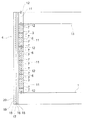
本発明の建築構造の一例を、図1〜図3に基づいて詳細に説明する。図示した建築構造は、図1、図2に示すように、木材製の土台1に所定間隔で立設された柱2の間に内壁3が配置され、内壁3との間に空間を設けることなく、内壁3の外面に直に外壁4を取付けた。図1に示す壁構造は真壁であるが、壁の種類はこれには限られず大壁であってもよい。
(Embodiment 1)
An example of the building structure of the present invention will be described in detail with reference to FIGS. In the illustrated building structure, as shown in FIGS. 1 and 2, an
柱2は3寸角、4寸角といった各種寸法の角材であって、溝5が柱2の側面の外面に近い部分に柱の軸に沿って(長手方向に)形成されている。溝5の形状、寸法は任意に選択することができる。柱2は、杉や檜であることが望ましいが、その他任意の素材を用いることができる。本実施形態では、各柱2は、同じ太さに成形されたものを用いている。
The
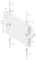
前記内壁3には図3に示すような建築用パネル6が使用され、それが隣合う柱2の間に配置されている。建築用パネル6には芯を持った(芯持ちの)木の内壁材7を複数本、横或いは縦一列に並べて、連結具や接着剤等の任意の手段によって連結してある。内壁材7は図のように角材であることが望ましいが、板材など、他の形状とすることもできる。内壁材7は杉や檜であることが望ましいが、他の任意の木材を用いることができる。内壁材7の厚さは20mm〜60mm、幅は45mm〜150mm、長さは900mm〜1800mmの間とすることが望ましいが、任意のサイズとすることができる。一例として、内壁材7が角材の場合、45mm角、長さ900mmの角材を用いることができる。また、内壁材7が板材の場合は、一例として、厚さ45mm、幅150mm、長さ900mmの板材を用いることも可能である。
また、前記内壁材7に用いる角材や板材等は、人工乾燥又は自然乾燥等によって、含水率を20%以下としたものを用いることが望ましい。これによって、内壁3の形成後に内壁材7が乾燥して、内壁3の捩れや歪みの発生を防ぐことができ、内壁3と外壁4との間に隙間ができなくなる。建築用パネル6の長手方向両端部は、一部が切り欠かれて突起部9が形成されており、その突起部9を前記柱2の溝5と組み合わせ可能としてある。建築用パネル6の側面には挿通孔10が建築用パネル6を幅方向に貫通して開口されている。挿通孔10は、一枚の建築用パネル6の長手方向両端寄り二箇所に開口されている。挿通孔10の数及び開口位置は図に示すものに限られず、任意の数及び開口位置とすることができる。
A
Moreover, it is desirable to use a square or plate material used for the
多数本の内壁材7が連結された建築用パネル6同士は、例えば、図3に示すようにして連結されている。連結する建築用パネル6の挿通孔10に連結ボルト11を差し込んで、その連結ボルト11の両端を建築用パネル6の挿通孔10の両端(図3では上下)から突出させる。その各建築用パネル6の連結ボルト11の突出端部同士を高ナット12にねじ込んで、2本の連結ボルト11同士を連結させることにより、各建築用パネル6を連結する。高ナット12は連結する二枚の建築用パネル6の挿通孔10に跨がせて埋め込んでおく。
The
建築用パネル6は数本の内壁材7を上下或いは横方向に並べて一枚にしておくのではなく、建物の設置箇所に数本の内壁材7を上下或いは横方向に並べ、それらを連結ボルト11と高ナット12を使用して連結することもできる。
The
内壁3となる建築用パネル6は、図1に示すように、その両端の突起部9を柱2の溝5に嵌め込んで、隣り合う柱2と柱2の間に配置される。この場合、図2に示すように、建築用パネル6の外面を柱2の外側面に揃えてある。また、建築用パネル6の下端は土台1に、上端は天井13に連結固定されている。この場合の固定手段は任意に選択できるが、例えば、連結ボルト11と高ナット12を使用することができる。
As shown in FIG. 1, the
外壁4は、図1、図2に示すように、内壁3の外面及び柱2の外側面との間に空間を設けることなく、内壁3の外面及び柱2の外側面に密着させて直に取り付けてある。外壁4は多層に構成されている。内壁3の外面及び柱2の外側面のすぐ外側に下地材15を釘、ビス等によって取付け、下地材15の外側に防湿シート16を張り、防湿シート16の外側に断熱材17をビス止めし、その上にラス網18を張り、ラス網18の上に下塗り(ラス擦り)、セメントモルタル(コンクリートモルタル)19を塗り、その上に、しっくい塗り又はリシン掻き落とし等により仕上げ面20を形成してある。下地材15にはベニヤ板等の構造合板を使用することができ、断熱材17には押出ポリスチレン三種断熱材とか他の任意の断熱材を用いることができる。
As shown in FIGS. 1 and 2, the
本発明の建築構造は、図4に示すように、建物の基礎部分にヒーター等の加熱体を設けて蓄熱可能として、床を暖房することができるようにしてある。同図に示すように、基礎は上基礎21と下基礎22とに分かれて形成され、上基礎21と下基礎22との間に防湿シート23が配置されている。上基礎21と下基礎22との間には防湿シート23のみならず断熱材等をも配置することもできる。前記下基礎22、上基礎21は共にコンクリート製である。上基礎1は土台支持部21aが高く、その内側が一段低く形成されている。上基礎21の内部には加熱器24が配置されている。加熱器24には電熱ヒーターが使用されている。上基礎21の低く形成された部分には砂利や砂等の蓄熱材25が敷き詰められている。上基礎21の土台支持部21aには木材製の土台1が備えられている。砂利25の上には板材26が敷設され、板材26の上には根太27が配置されている。根太27の上には床板28が敷設されて床が形成されている。床板28は前記内壁材7と同じ角材又は板材を並べたものとすることができる。ヒーターは通電すると発熱して上基礎21を加温すると共に砂利等の蓄熱材25をも加熱して蓄熱でき、床板28を暖めることができる。前記加熱器24にはヒーター以外の加熱器、例えば、蒸気や湯を通す管を配管することもできる。また、前記蓄熱材25に用いる砂利のサイズは、任意のものとすることができる。前記板材26は石製、木製等の任意のものとすることができる。
As shown in FIG. 4, the building structure of the present invention is configured such that a heating body such as a heater is provided at the base portion of a building so that heat can be stored and the floor can be heated. As shown in the figure, the foundation is divided into an
(その他の実施形態)
本発明における内壁は、実施例1の建築用パネル6を組み合わせる構成には限られず、多数本の内壁材7を縦にして横一列に並べ、それらを長い連結具で複数箇所連結して幅広の建築用パネルを形成し、そのパネルで土台から天井までの長い壁面パネルとすることもできる。本発明の内壁は他の任意の方法で形成することもできる。
(Other embodiments)
The inner wall in the present invention is not limited to the construction in which the
本発明における外壁も、実施形態1に示す建材の組み合わせに限らず、不燃材、難燃材、断熱材、防湿材、吸音材の一種又は二種以上を任意に組み合わせたものとすることができる。 The outer wall in the present invention is not limited to the combination of building materials shown in the first embodiment, and may be any combination of one or more of noncombustible materials, flame retardant materials, heat insulating materials, moistureproof materials, and sound absorbing materials. .
本発明の建築構造は、木造の戸建住宅に限らず、公共施設とか、他の建物にも応用することができる。 The architectural structure of the present invention can be applied not only to wooden detached houses but also to public facilities and other buildings.
1 土台
2 柱
3 内壁
4 外壁
6 建築用パネル
7 内壁材
11 パネル連結ボルト
12 高ナット
16 防湿シート
17 断熱材
21 基礎上部
24 加熱器
25 蓄熱材
DESCRIPTION OF
Claims (4)
The building structure according to any one of claims 1 to 3, wherein a heater is provided at a base portion of the building so that heat can be stored.
Priority Applications (1)
| Application Number | Priority Date | Filing Date | Title |
|---|---|---|---|
| JP2004105893A JP2005290778A (en) | 2004-03-31 | 2004-03-31 | Building structure |
Applications Claiming Priority (1)
| Application Number | Priority Date | Filing Date | Title |
|---|---|---|---|
| JP2004105893A JP2005290778A (en) | 2004-03-31 | 2004-03-31 | Building structure |
Publications (1)
| Publication Number | Publication Date |
|---|---|
| JP2005290778A true JP2005290778A (en) | 2005-10-20 |
Family
ID=35324027
Family Applications (1)
| Application Number | Title | Priority Date | Filing Date |
|---|---|---|---|
| JP2004105893A Pending JP2005290778A (en) | 2004-03-31 | 2004-03-31 | Building structure |
Country Status (1)
| Country | Link |
|---|---|
| JP (1) | JP2005290778A (en) |
Cited By (1)
| Publication number | Priority date | Publication date | Assignee | Title |
|---|---|---|---|---|
| JP2011247070A (en) * | 2010-05-28 | 2011-12-08 | Koichi Nemoto | Assembly method using thinnings and construction method of the same |
Citations (7)
| Publication number | Priority date | Publication date | Assignee | Title |
|---|---|---|---|---|
| JPS56128854A (en) * | 1980-03-13 | 1981-10-08 | Shinichi Toumaru | Side wall method of building |
| JPS61165447A (en) * | 1985-01-17 | 1986-07-26 | タウン・アンド・カントリー・シーダ・ホームズ・インコーポレイテッド | Assembling panel for round thick wall system wherein pillar and frame are formed into panel |
| JPH02292438A (en) * | 1989-05-02 | 1990-12-03 | Yoshinori Okura | Building structure of wooden house |
| JPH1068178A (en) * | 1996-08-29 | 1998-03-10 | Ig Tech Res Inc | House |
| JP2001336241A (en) * | 2000-05-29 | 2001-12-07 | Naoki Shimoji | Wall structure of wooden building |
| JP2003056061A (en) * | 2001-08-10 | 2003-02-26 | Yoshihiro Tokai | Wooden building |
| JP2003176585A (en) * | 2001-06-15 | 2003-06-24 | Deguchi Kensetsu:Kk | Wall structure of wooden building |
-
2004
- 2004-03-31 JP JP2004105893A patent/JP2005290778A/en active Pending
Patent Citations (7)
| Publication number | Priority date | Publication date | Assignee | Title |
|---|---|---|---|---|
| JPS56128854A (en) * | 1980-03-13 | 1981-10-08 | Shinichi Toumaru | Side wall method of building |
| JPS61165447A (en) * | 1985-01-17 | 1986-07-26 | タウン・アンド・カントリー・シーダ・ホームズ・インコーポレイテッド | Assembling panel for round thick wall system wherein pillar and frame are formed into panel |
| JPH02292438A (en) * | 1989-05-02 | 1990-12-03 | Yoshinori Okura | Building structure of wooden house |
| JPH1068178A (en) * | 1996-08-29 | 1998-03-10 | Ig Tech Res Inc | House |
| JP2001336241A (en) * | 2000-05-29 | 2001-12-07 | Naoki Shimoji | Wall structure of wooden building |
| JP2003176585A (en) * | 2001-06-15 | 2003-06-24 | Deguchi Kensetsu:Kk | Wall structure of wooden building |
| JP2003056061A (en) * | 2001-08-10 | 2003-02-26 | Yoshihiro Tokai | Wooden building |
Cited By (1)
| Publication number | Priority date | Publication date | Assignee | Title |
|---|---|---|---|---|
| JP2011247070A (en) * | 2010-05-28 | 2011-12-08 | Koichi Nemoto | Assembly method using thinnings and construction method of the same |
Similar Documents
| Publication | Publication Date | Title |
|---|---|---|
| JP4049564B2 (en) | Fireproof partition wall and its construction method | |
| US20100199586A1 (en) | Insulation system for cement walls | |
| JP3733370B1 (en) | Wall panel, wall panel fixing structure, and wall panel fixing method | |
| US8122657B2 (en) | Metal “log” buildings with rigid insulation | |
| KR20120002908U (en) | Prefab Tile Finisher | |
| JP2006104702A (en) | High heat insulating - combustion resisting foundation building material | |
| JP2005290778A (en) | Building structure | |
| RU2235834C1 (en) | Panel for additional wall heat insulation | |
| CN221663918U (en) | Waterproof building wall panel | |
| KR100850767B1 (en) | Internal wall structure | |
| KR20070005334A (en) | Prefabricated wall panel and building wall using the same | |
| US3872640A (en) | Prefabricated structural unit body and structures thereof | |
| JP2020101021A (en) | Fireproof laminate lumber | |
| ES2336528B2 (en) | ARCHITECTURAL WALL FOR PREFABRICATED HOUSES. | |
| RU105652U1 (en) | SMALL BUILDING OF MODULAR DESIGN (OPTIONS) | |
| JP2002356943A (en) | Exterior wall structure | |
| JP7745402B2 (en) | outer wall | |
| RU2840588C1 (en) | Collapsible prefabricated house from wooden blocks and method of its erection | |
| JP2001355303A (en) | Substrate board used for both interior and exterior finishing, fastening tool for the same, and outside insulation construction method | |
| JP7479686B2 (en) | Wall panels | |
| KR102575383B1 (en) | Acoustic click louver board device having lower rail to facilitate coupling | |
| KR101923596B1 (en) | Indoor wall surface finish for apartment houses | |
| JPH10237958A (en) | Lightweight cellular concrete panel connecting structures, boards and shelters | |
| ES2334955B1 (en) | NEW CLOSURE TRAINING SYSTEM AND ASSEMBLY PROCEDURE OF THE SAME. | |
| JP2010024809A (en) | Forced outer-wall air circulation type wood frame construction |
Legal Events
| Date | Code | Title | Description |
|---|---|---|---|
| A621 | Written request for application examination |
Free format text: JAPANESE INTERMEDIATE CODE: A621 Effective date: 20070329 |
|
| A977 | Report on retrieval |
Free format text: JAPANESE INTERMEDIATE CODE: A971007 Effective date: 20081127 |
|
| A131 | Notification of reasons for refusal |
Free format text: JAPANESE INTERMEDIATE CODE: A131 Effective date: 20081202 |
|
| A521 | Written amendment |
Free format text: JAPANESE INTERMEDIATE CODE: A523 Effective date: 20090202 |
|
| A131 | Notification of reasons for refusal |
Free format text: JAPANESE INTERMEDIATE CODE: A131 Effective date: 20090331 |
|
| A02 | Decision of refusal |
Free format text: JAPANESE INTERMEDIATE CODE: A02 Effective date: 20090721 |