JP2005290746A - Irifukugi and interior space using it - Google Patents
Irifukugi and interior space using it Download PDFInfo
- Publication number
- JP2005290746A JP2005290746A JP2004105097A JP2004105097A JP2005290746A JP 2005290746 A JP2005290746 A JP 2005290746A JP 2004105097 A JP2004105097 A JP 2004105097A JP 2004105097 A JP2004105097 A JP 2004105097A JP 2005290746 A JP2005290746 A JP 2005290746A
- Authority
- JP
- Japan
- Prior art keywords
- wall
- floor
- skirting board
- vertical surface
- wall surface
- Prior art date
- Legal status (The legal status is an assumption and is not a legal conclusion. Google has not performed a legal analysis and makes no representation as to the accuracy of the status listed.)
- Pending
Links
Images
Landscapes
- Finishing Walls (AREA)
Abstract
Description
本発明は、床面と壁面との間に配される巾木に関し、壁面より内側に引っ込めて形成される入巾木に関するものである。 The present invention relates to a baseboard arranged between a floor surface and a wall surface, and relates to an input baseboard formed by being retracted inside the wall surface.
一般に、室内の床面と壁面との間には見切りとして巾木が配され、掃除機の衝撃や汚れ等から壁面を守るようにしている。また、巾木は床面と壁面とをなじみよく納めるために使用されるものである。
このような巾木において、一般的な形状のものとして出巾木が知られており、壁面から外側に突出した形状に形成されて、その高さや材質、表面に掘り込みを設けることで多様なデザインのものが製造されている。
また、巾木には上述の出巾木の他に、壁面より内側に引っ込めて形成された入巾木が知られており、この入巾木によればモダンスタイルと呼ばれるインテリアスタイルを表現できるようにしている。
この入巾木に関しては、その取り付けを容易として、収縮がおこっても外観を損ねないようにした入巾木が公開されている(特許文献1参照)。
Generally, a baseboard is arranged between the floor surface and the wall surface in the room as a parting line so as to protect the wall surface from the impact or dirt of the vacuum cleaner. The baseboard is used to fit the floor surface and the wall surface well.
In such a skirting board, an outboard skirting board is known as a general shape, and is formed in a shape protruding outward from the wall surface. Designed ones are manufactured.
In addition to the above-mentioned skirting boards, there are other skirting boards that are formed by retracting from the wall surface. According to this skirting board, an interior style called modern style can be expressed. I have to.
With regard to this skirting board, a skirting board has been disclosed that facilitates its attachment and does not impair the appearance even when contracted (see Patent Document 1).
しかしながら、特許文献1に記載されるような従来の入巾木の構成においては、壁面の下部を受けることができるように、保持部分を備えているが、床面との連結に配慮されたものではない。
また、モダンスタイルと呼ばれるインテリアスタイルを表現するためには、意匠性が高く、かつ、シンプルなデザインに仕上げられることが必要であった。
このような問題点を解決するとともに、意匠性の高い入巾木を提供するために、本発明においては、施工性の向上を図るとともに意匠性の向上を図るものであり、該入巾木を適用することで、低コストでインテリア性が高く高級感のある室内空間を提供できるようにするものである。
However, in the structure of the conventional skirting as described in
Moreover, in order to express the interior style called modern style, it was necessary to have a high design and a simple design.
In order to solve such problems and to provide a skirting board with high designability, in the present invention, it is intended to improve the workability and improve the designability. By applying it, it is possible to provide a high-quality indoor space with high interior quality and low cost.
本発明の解決しようとする課題は以上の如くであり、次にこの課題を解決するための手段を説明する。 The problems to be solved by the present invention are as described above. Next, means for solving the problems will be described.
即ち、請求項1においては、床面と壁面との連結部に配され、壁面より内側に凹状に引っ込めて形成される入巾木を、縦面部分から水平方向に突出して壁下地を保持する壁保持部と、該壁保持部より下位置の縦面部分にて形成される凹部と、前記凹部の下方の縦面部分から水平方向に突出された床差込部と、から構成したものである。 That is, according to the first aspect of the present invention, the purse that is arranged in the connecting portion between the floor surface and the wall surface and is recessed inwardly from the wall surface protrudes in the horizontal direction from the vertical surface portion to hold the wall base. It is composed of a wall holding part, a recess formed in a vertical surface part below the wall holding part, and a floor insertion part protruding in a horizontal direction from a vertical surface part below the concave part. is there.
請求項2においては、前記入巾木は、アルミ金属製で構成されるとともに、発色性塗装、又は、アルマイト処理仕上げが施されているものである。 According to a second aspect of the present invention, the skirting board is made of an aluminum metal, and has a chromic coating or an alumite treatment finish.
請求項3においては、前記壁保持部と前記凹部との連結部、及び、前記床差込部と前記凹部との連結部はR形状に形成されているものである。
In
請求項4においては、請求項1、2、又は3に記載の入巾木を床面と壁面との連結部に適用するとともに、壁面と天井部との連結部に底目地仕上げを適用したものである。
In claim 4, the skirting board according to
本発明の効果として、以下に示すような効果を奏する。 As effects of the present invention, the following effects can be obtained.
請求項1においては、入巾木を配置する際の施工効率を向上できるとともに、施工後の収まりがよく、がたつきを防止することができる。
In
請求項2においては、アルミの素材感をよりよく表現して、意匠性を高めることができる。
In
請求項3においては、入巾木の意匠性を向上できるとともに、塵埃を溜まりにくくすることができる。 According to the third aspect of the present invention, it is possible to improve the design of the skirting board and make it difficult to collect dust.
請求項4においては、排他性や無性格性を表現できるモダンスタイルの室内空間を低コストで提供することができる。また、コストをかけずに高級感のある室内空間を提供することができる。 According to the fourth aspect of the present invention, it is possible to provide a modern-style indoor space that can express exclusivity and personality at a low cost. In addition, it is possible to provide a high-quality indoor space without cost.
次に、発明の実施の形態を説明する。
図1は本発明の一実施形態に係る入巾木の構成を示す斜視図、図2は同じく側面断面図、図3は天井底目地構造を示す斜視図、図4は同じく側面断面図である。
Next, embodiments of the invention will be described.
FIG. 1 is a perspective view showing a structure of a baseboard according to an embodiment of the present invention, FIG. 2 is a side sectional view, FIG. 3 is a perspective view showing a ceiling bottom joint structure, and FIG. 4 is a side sectional view. .
まず、本発明に係る入巾木1の構成を説明する。
図1に示すように入巾木1は床面と壁面との連結部に配置され、壁面に対して内側に凹状に引っ込めた形状に形成されている。
該入巾木1は、その上部構造により壁2を支持するとともに、その下部構造により床板3を挿し込んで配置できるようにしている。
First, the configuration of the
As shown in FIG. 1, the
The
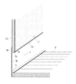
前記入巾木1のより具体的な構造を図2により説明すると、入巾木1は床面に対して垂直方向に立設された縦面部分1dと、該縦面部分1dから水平方向に突出した壁保持部1a及び床差込部1cと、から構成されている。前記壁保持部1aと、前記床差込部1cとに挟まれた位置における縦面部分1dに、凹状に引っ込められた凹部1bが形成されており、該凹部1bにより入巾木1の意匠面が形成されている。
前記凹部1bの上下方向の幅(即ち、壁保持部1aと床差込部1cとの距離)は、本実施例においては5cm程度に構成されているが、長さは限定するものではない。
A more specific structure of the
The vertical width of the
前記壁保持部1aは縦面部分1dから室内側に壁下地2aの厚さと略同じ長さで水平方向に突出されており、該壁保持部1aの上面と壁保持部1aより上位置の縦面部分1dにより石膏ボード等で構成される壁下地2aを保持できるようにしている。
また、前記壁保持部1aの先端部側は上方に屈曲されて屈曲部1eが形成されており、該屈曲部1eに壁下地2aを係止して室内側に端部が出ないように、つまり、壁下地2aの下端が壁保持部1aの上面に納まるように配置して、めくれ等を防止している。該屈曲部1eの上面には壁下地2aの表面に貼設される壁装材2bが配されるものである。
なお、本実施例における壁保持部1aの幅は14cm程度に構成されているものであるが、壁下地2aの厚みに合わせて変更することも可能である。
The
Further, the distal end side of the
In addition, although the width | variety of the
前記床差込部1cは前記壁保持部1aの下方であって、縦面部分1dから室内側に水平方向に突出されており、該床差込部1cの下面に床板3を挿し込んで、床板3の端部を床差込部1cより下位置の縦面部分1dに当接させて、配置できるようにしている。
The
また、縦面部分1dと壁保持部1aとの連結部、及び、縦面部分1dと床差込部1cとの連結部の意匠面側は共にR状に形成されており、つまり、室内側の縦面部分1dと壁保持部1aとの交差部、及び、縦面部分1dと床差込部1cとの交差部は曲面に形成して、意匠性の向上を図っているものである。
Further, the design surface side of the connecting portion between the
このような入巾木1の構成において、施工の際には入巾木1の壁保持部1aの上面に壁下地2aを嵌め込むとともに、床差込部1cの下面に沿わせて床板の端部を嵌め込むのである。そして、縦面部分1dに壁下地2a及び床板3を押し込んで当接させることで、入巾木1のがたつきが抑えられるのである。
In such a construction of the
以上のように、本発明の入巾木1においては壁保持部1aの構造にて壁2の下端部を受けることができ、床差込部1cにて床面を挿し込むことができるようにしているので、入巾木1を配置する際の施工効率を向上することができる。
As described above, in the
また、前記入巾木1の材質はアルミ金属製で形成され、発色性塗装もしくはアルマイト処理にて仕上げ処理されており、アルミの素材感をよりよく表現できるように考慮しているものである。但し、材質はアルミに限定するものではなく、ステンレス等の金属等で構成することも可能である。
このように、入巾木1を仕上げ処理することで、シンプルモダンのスタイルとして高級感のある入巾木を低コストで提供することができる。
In addition, the material of the
In this way, by finishing the
続いて、上述の入巾木1を床面と壁面との連結部に配設するとともに、壁面と天井ボードとの連結部に底目地仕上げを適用した室内空間について説明する。
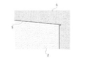
図3に示すように、床面と壁面との連結部に入巾木を配置するとともに、壁2と天井ボード4との連結部には底目地仕上げを適用している。
前記底目地仕上げは壁面に対して天井部が凹状にへこんで構成されており、コストをかけずにシンプルモダンのスタイルとして、室内空間の高級感を高めることができるようにしている。
Next, a description will be given of an indoor space in which the above-mentioned
As shown in FIG. 3, the skirting boards are arranged at the connecting portion between the floor surface and the wall surface, and the bottom joint finish is applied to the connecting portion between the
The bottom joint finish is configured such that the ceiling portion is recessed in a concave shape with respect to the wall surface, and it is possible to enhance the luxury of the indoor space as a simple modern style without cost.
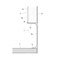
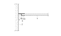
前記天井底目地仕上げは、例えば、図4に示すように、天井ボード4と壁2との間に配置される天井用底目地連結具6にて構成される。
天井用底目地連結具6は天井ボード4の端部を保持する断面視「コ」字状の保持部6aと、天井面に対して凹状に窪んだ天井底目地部5を形成する凹部6bとから構成されているものである。
また、前記天井用底目地連結具6は図示しない野縁等に固定されて天井部に対して固定されるとともに、壁2に対して固定されているものである。
The ceiling bottom joint finish is constituted by a ceiling bottom
The
Further, the ceiling
このように、上述の入巾木1と天井底目地構造とを併用することで、低コストで高級感の高い室内空間を提供することができるのである。また、シンプルモダンの室内空間を実現することができるのである。
Thus, by using the above-mentioned
1 入巾木
1a 壁保持部
1b 凹部
1c 床差込部
1d 縦面部分
1e 屈曲部
2 壁
2a 壁下地
2b 壁装材
3 床板
4 天井ボード
5 天井底目地部
6 天井用底目地連結具
DESCRIPTION OF
Claims (4)
縦面部分から水平方向に突出して壁下地を保持する壁保持部と、
該壁保持部より下位置の縦面部分にて形成される凹部と、
前記凹部の下方の縦面部分から水平方向に突出された床差込部と、
から構成したことを特徴とする入巾木。 Arranged at the connecting part between the floor surface and the wall surface,
A wall holding part that protrudes in the horizontal direction from the vertical surface part and holds the wall base;
A recess formed in a vertical surface portion below the wall holding portion;
A floor insertion portion protruding in a horizontal direction from a vertical surface portion below the concave portion;
Irifukugi characterized by comprising
アルミ金属製で構成されるとともに、
発色性塗装、又は、アルマイト処理仕上げが施されている
ことを特徴とする請求項1に記載の入巾木。 The Irakigi is
Made of aluminum metal,
The skirting board according to claim 1, wherein a colored paint or an alumite treatment finish is applied.
Priority Applications (1)
| Application Number | Priority Date | Filing Date | Title |
|---|---|---|---|
| JP2004105097A JP2005290746A (en) | 2004-03-31 | 2004-03-31 | Irifukugi and interior space using it |
Applications Claiming Priority (1)
| Application Number | Priority Date | Filing Date | Title |
|---|---|---|---|
| JP2004105097A JP2005290746A (en) | 2004-03-31 | 2004-03-31 | Irifukugi and interior space using it |
Publications (1)
| Publication Number | Publication Date |
|---|---|
| JP2005290746A true JP2005290746A (en) | 2005-10-20 |
Family
ID=35323995
Family Applications (1)
| Application Number | Title | Priority Date | Filing Date |
|---|---|---|---|
| JP2004105097A Pending JP2005290746A (en) | 2004-03-31 | 2004-03-31 | Irifukugi and interior space using it |
Country Status (1)
| Country | Link |
|---|---|
| JP (1) | JP2005290746A (en) |
Cited By (4)
| Publication number | Priority date | Publication date | Assignee | Title |
|---|---|---|---|---|
| GB2476170A (en) * | 2009-12-11 | 2011-06-15 | Easibathe Ltd | Trim strip device between a floor covering and a wall covering |
| JP2012021350A (en) * | 2010-07-16 | 2012-02-02 | Panasonic Electric Works Co Ltd | Concave baseboard and finishing structure of floor-wall boundary using the same |
| JP2012021349A (en) * | 2010-07-16 | 2012-02-02 | Panasonic Electric Works Co Ltd | Concave baseboard and finishing structure of floor-wall boundary using the same |
| KR102556673B1 (en) * | 2022-03-10 | 2023-07-18 | 박재석 | Skirting board |
Citations (6)
| Publication number | Priority date | Publication date | Assignee | Title |
|---|---|---|---|---|
| JPS4615172Y1 (en) * | 1966-03-05 | 1971-05-27 | ||
| JPS49130021A (en) * | 1973-04-20 | 1974-12-12 | ||
| JPS55150149U (en) * | 1979-04-16 | 1980-10-29 | ||
| JPH0729188U (en) * | 1993-11-01 | 1995-06-02 | 株式会社エービーシー商会 | Baseboard |
| JP2000087545A (en) * | 1998-09-10 | 2000-03-28 | Misawa Homes Co Ltd | Building material |
| JP2000220285A (en) * | 1999-01-29 | 2000-08-08 | Noda Corp | Finished structure of baseboard member and floor member |
-
2004
- 2004-03-31 JP JP2004105097A patent/JP2005290746A/en active Pending
Patent Citations (6)
| Publication number | Priority date | Publication date | Assignee | Title |
|---|---|---|---|---|
| JPS4615172Y1 (en) * | 1966-03-05 | 1971-05-27 | ||
| JPS49130021A (en) * | 1973-04-20 | 1974-12-12 | ||
| JPS55150149U (en) * | 1979-04-16 | 1980-10-29 | ||
| JPH0729188U (en) * | 1993-11-01 | 1995-06-02 | 株式会社エービーシー商会 | Baseboard |
| JP2000087545A (en) * | 1998-09-10 | 2000-03-28 | Misawa Homes Co Ltd | Building material |
| JP2000220285A (en) * | 1999-01-29 | 2000-08-08 | Noda Corp | Finished structure of baseboard member and floor member |
Cited By (4)
| Publication number | Priority date | Publication date | Assignee | Title |
|---|---|---|---|---|
| GB2476170A (en) * | 2009-12-11 | 2011-06-15 | Easibathe Ltd | Trim strip device between a floor covering and a wall covering |
| JP2012021350A (en) * | 2010-07-16 | 2012-02-02 | Panasonic Electric Works Co Ltd | Concave baseboard and finishing structure of floor-wall boundary using the same |
| JP2012021349A (en) * | 2010-07-16 | 2012-02-02 | Panasonic Electric Works Co Ltd | Concave baseboard and finishing structure of floor-wall boundary using the same |
| KR102556673B1 (en) * | 2022-03-10 | 2023-07-18 | 박재석 | Skirting board |
Similar Documents
| Publication | Publication Date | Title |
|---|---|---|
| KR200456095Y1 (en) | Baseboard starter and construction structure using the same | |
| JP2005290746A (en) | Irifukugi and interior space using it | |
| KR100837669B1 (en) | Exterior finishing structure and installation method | |
| JP2011140767A (en) | Staircase structure, fixing implement, and method for assembling the staircase structure | |
| KR200174254Y1 (en) | The outer wall of a building | |
| JP2005179987A (en) | Exterior wall reform structure | |
| JP2012067563A (en) | External wall corner part settling member and external wall corner part settling structure | |
| KR20000008475U (en) | Prefabricated bathroom wall made by connecting wall panels with brackets for flat and corner connections | |
| JP2008180042A (en) | Partition structure between bathroom and lavatory | |
| KR200261357Y1 (en) | Window Frame Cover for Widening Living Room | |
| JP3146398U (en) | Baseboard starter and construction structure using it | |
| JP4042686B2 (en) | Siding character | |
| JP6843642B2 (en) | Joiner for outside corner | |
| JP2002038706A (en) | Exterior-wall outside angle structure | |
| JP2001152681A (en) | Ceiling structure of equipment unit and its construction method | |
| JP4706370B2 (en) | External wall opening | |
| KR200341813Y1 (en) | Molding for construction of ceiling finishing member | |
| JP2008133605A (en) | Structure for mounting piping in exterior wall | |
| JP4199652B2 (en) | Unit room wall panel connection structure | |
| JPH10102646A (en) | Partition wall structure | |
| JP2010024614A (en) | Mounting structure and method for exterior panel and furring strips | |
| KR100676295B1 (en) | Fire door frame | |
| JP2003213884A (en) | End part structure | |
| JPH11336286A (en) | Exterior material joints and joint structures | |
| JP2005180031A (en) | Modesty panel |
Legal Events
| Date | Code | Title | Description |
|---|---|---|---|
| A621 | Written request for application examination |
Free format text: JAPANESE INTERMEDIATE CODE: A621 Effective date: 20061120 |
|
| A977 | Report on retrieval |
Free format text: JAPANESE INTERMEDIATE CODE: A971007 Effective date: 20100122 |
|
| A131 | Notification of reasons for refusal |
Free format text: JAPANESE INTERMEDIATE CODE: A131 Effective date: 20100126 |
|
| A02 | Decision of refusal |
Free format text: JAPANESE INTERMEDIATE CODE: A02 Effective date: 20100525 |