JP2005290726A - Support frame for bathroom unit, and reinforcing material used for the same - Google Patents
Support frame for bathroom unit, and reinforcing material used for the same Download PDFInfo
- Publication number
- JP2005290726A JP2005290726A JP2004104500A JP2004104500A JP2005290726A JP 2005290726 A JP2005290726 A JP 2005290726A JP 2004104500 A JP2004104500 A JP 2004104500A JP 2004104500 A JP2004104500 A JP 2004104500A JP 2005290726 A JP2005290726 A JP 2005290726A
- Authority
- JP
- Japan
- Prior art keywords
- bathroom unit
- reinforcing material
- leg
- support
- pedestal portion
- Prior art date
- Legal status (The legal status is an assumption and is not a legal conclusion. Google has not performed a legal analysis and makes no representation as to the accuracy of the status listed.)
- Granted
Links
- 239000012779 reinforcing material Substances 0.000 title claims abstract description 34
- NJPPVKZQTLUDBO-UHFFFAOYSA-N novaluron Chemical group C1=C(Cl)C(OC(F)(F)C(OC(F)(F)F)F)=CC=C1NC(=O)NC(=O)C1=C(F)C=CC=C1F NJPPVKZQTLUDBO-UHFFFAOYSA-N 0.000 claims abstract description 48
- 239000007769 metal material Substances 0.000 claims abstract description 11
- 239000000463 material Substances 0.000 abstract description 18
- 238000005096 rolling process Methods 0.000 abstract description 5
- 238000012423 maintenance Methods 0.000 abstract description 4
- 238000003287 bathing Methods 0.000 abstract description 3
- 238000004519 manufacturing process Methods 0.000 abstract description 2
- 230000003014 reinforcing effect Effects 0.000 description 17
- 229910000831 Steel Inorganic materials 0.000 description 13
- 239000010959 steel Substances 0.000 description 13
- 238000005406 washing Methods 0.000 description 6
- 229920003002 synthetic resin Polymers 0.000 description 4
- 239000000057 synthetic resin Substances 0.000 description 4
- 229910001220 stainless steel Inorganic materials 0.000 description 3
- 239000010935 stainless steel Substances 0.000 description 3
- XEEYBQQBJWHFJM-UHFFFAOYSA-N Iron Chemical compound [Fe] XEEYBQQBJWHFJM-UHFFFAOYSA-N 0.000 description 2
- 238000005452 bending Methods 0.000 description 2
- 239000002184 metal Substances 0.000 description 2
- 229910052751 metal Inorganic materials 0.000 description 2
- 230000002093 peripheral effect Effects 0.000 description 2
- 230000015572 biosynthetic process Effects 0.000 description 1
- 238000010276 construction Methods 0.000 description 1
- 230000000694 effects Effects 0.000 description 1
- 230000001771 impaired effect Effects 0.000 description 1
- 238000009434 installation Methods 0.000 description 1
- 229910052742 iron Inorganic materials 0.000 description 1
- 238000003860 storage Methods 0.000 description 1
Images
Landscapes
- Residential Or Office Buildings (AREA)
Abstract
Description
本発明は浴室ユニットの支持架台に関し、更に詳しくは例えば洗い場の床パンや浴槽等の浴室ユニットを支持するための浴室ユニットの支持架台及びこれに用いる補強材に関するものである。 The present invention relates to a support frame for a bathroom unit, and more particularly to a support frame for a bathroom unit for supporting a bathroom unit such as a floor pan or a bathtub in a washing place and a reinforcing material used therefor.
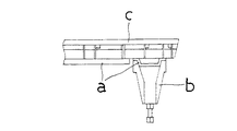
従来この種の支持架台としては、例えば図9に示されるように、架台aの周辺部等の適宜位置に、合成樹脂材で成型された逆円錐形の脚bを取り付け、この脚bで床パンcに加わる荷重を支持するよう形成しているものがある。 Conventionally, as this type of support frame, for example, as shown in FIG. 9, an inverted conical leg b molded from a synthetic resin material is attached to an appropriate position such as a peripheral part of the frame a, and the floor is supported by this leg b. Some are formed to support the load applied to the pan c.
また従来この種の架台としては、例えば洗い場の略中央部から両側端に向かって緩やかな下り傾斜状に補強材を設け、この補強材のバネ性を利用して床パンを支持するよう形成しているものがある(例えば特許文献1参照)。
ところで従来この種の架台の脚は、横揺れを防止するため、合成樹脂材等の形成材料を大量に用いて堅固に形成する必要があり、また洗い場の四隅に対応する位置だけではなく、中央位置等にも設ける必要があった。従って従来品は、脚が大型化して嵩張り易かったから、その分、コストが高く付き、重くなるのを避けられず、また床下のメンテナンススペースを狭小化させる、という問題点があった。
また特許文献1記載の従来品の場合は、補強材を床下にアーチ形に曲げながらその両端を取り付ける必要があるため、この種の取付作業に手間暇がかかるのを避けられなかった。またこれによると、補強材のバネ性を利用するため、洗い場の中央部を歩くと僅かに沈む感じを受け、快適な入浴感を害する、という問題点があった。
By the way, the legs of this type of gantry conventionally have to be firmly formed by using a large amount of synthetic resin or other forming material in order to prevent rolling, and not only at the positions corresponding to the four corners of the washing place, but also at the center. It was also necessary to provide the position. Therefore, the conventional product has a problem that the legs are large and easily bulky, and accordingly, the cost is high and it is inevitable that the legs become heavy, and the maintenance space under the floor is narrowed.
Further, in the case of the conventional product described in
本発明は、このような従来技術の問題点に鑑み、提案されたものである。
従って本発明の解決しようとする技術的課題は、脚の形成材料を節減でき、低コスト化、軽量化を図れ、床下のメンテナンススペースを狭小化させることなく、ぐらつき、横揺れを防止でき、製造、組立ても容易で快適な入浴感を害することもないよう形成した浴室ユニットの支持架台、及びこのような効果を奏するよう形成したこの架台に用いる補強材を提供することにある。
The present invention has been proposed in view of such problems of the prior art.
Therefore, the technical problem to be solved by the present invention is that the leg forming material can be saved, the cost and weight can be reduced, the wobbling and rolling can be prevented without reducing the maintenance space under the floor, Another object of the present invention is to provide a support frame for a bathroom unit formed so as to be easy to assemble and not impair a comfortable bathing feeling, and a reinforcing material used for the frame formed to exhibit such an effect.
本発明は、上記の課題を解決するため、次のような技術的手段を採る。
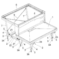
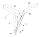
即ち本発明は、図1等に示されるように、浴室ユニット1を載せる水平状の台座部2と、この台座部2の棒状の脚3とで形成されている浴室ユニット1の支持架台であって、上記の台座部2と脚3に補強材4が斜めにわたされて取り付けられていることを特徴とする(請求項1)。
The present invention employs the following technical means in order to solve the above problems.
That is, as shown in FIG. 1 and the like, the present invention is a support frame for a
ここで、浴室ユニット1としては、例えば洗い場形成用の床パン、浴槽、浴槽を載せるための防水パン等がある。本発明の場合、台座部2は、通常、鋼材等で枠状に形成されるが、枠状に限定されるものではない。また補強材4は、例えば鉄板やステンレス鋼等の金属材で形成されるのが通例であるが、弾性変形する合成樹脂材等でも良く、その形成材料や形状は任意である。
Here, examples of the
而して本発明の課題を達成する他の構成としては、図1等に示されるように、浴室ユニット1としての浴槽を載せる水平状の台座部2と、この台座部2の上方に配置されて浴槽のフランジ部1bが係合される枠状の受け部材6と、この受け部材6を支持するため台座部2に起立状に設けられた支柱7とで形成されている浴室ユニット1の支持架台であって、上記の台座部2と支柱7に補強材4が斜めにわたされて取り付けられていることを特徴とするものがある(請求項2)。この本発明の場合、台座部2や補強材4の構成等は、上例と同様である。
Thus, as another configuration for achieving the object of the present invention, as shown in FIG. 1 and the like, a
またこの請求項2に係る本発明の場合は、隣り合う支柱7に筋かい9が交差状に設けられているのが好ましい(請求項3)。
なぜならこれによると、支柱7の連結状態が堅固になり、架台の強度を向上できるからである。
Further, in the case of the present invention according to
This is because, according to this, the connection state of the
また請求項1乃至3の何れかに記載の支持架台の場合は、補強材4の一端部4aが取り付けられる台座部2の取付面と、他端部4bが取り付けられる脚3又は支柱7の取付面との位置が、前後にずらされて配置され、補強材4が、金属材で細長い板状に形成されると共に、上記の各取付面にあてがわれる一端部4aと他端部4bとが平板状に形成され、且つこの一端部4aと他端部4bとの間の位置4cが断面略コの字形に屈曲形成されているのが好ましい(請求項4)。
Moreover, in the case of the support frame in any one of
なぜならこれによると、補強材4の取付面がずらされているため、その分、横揺れ、ぐらつきを抑えることができるからである。またこの場合は、補強材4が金属材の細長い板で形成され、且つ一端部4aと他端部4bとが平板状であるから、台座部2等の取付面の位置に合わせて一端部4a、他端部4bを曲げてぴったり取り付けることができ、台座部2と脚3、又は支柱7との位置関係を様々に変更でき、仕様変更に対応し易いからである。ここで、断面略コの字形とは、断面形状が、例えばホッチキスの針形、リップ溝形、ハット形等に形成されていることを意味する。
This is because according to this, the mounting surface of the reinforcing
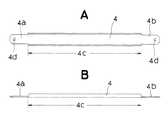
また本発明の補強材4としては、図4に示されるように、金属材で細長い板状に形成されると共に、台座部2の取付面と、脚3又は支柱7の取付面にあてがわれる一端部4aと他端部4bとが平板状に形成され、且つこの一端部4aと他端部4bとの間の位置4cが断面略コの字形に屈曲形成されているものがある(請求項5)。
As shown in FIG. 4, the reinforcing
この補強材4の場合は、一端部4aと他端部4bを除いて断面略コの字形に形成されているから、強度を高く維持できる。また金属材の細長い板で形成され、且つ一端部4aと他端部4bとが平板状であるから、これによると台座部2等の取付面の位置に合わせて一端部4a、他端部4bを曲げてぴったりと取り付けることができる。従って台座部2と脚3、又は支柱7との位置関係を様々に変更した支持架台を簡単に製造でき、設計や仕様変更に柔軟に対応できる。なお断面略コの字形の意味は、上記の場合と同様である。
In the case of this reinforcing
本発明の支持架台は、水平状の台座部と棒状の脚、又は支柱に、補強材を斜めにわたして取り付けているものである。
従って本発明によれば、本来、垂直から加わる荷重に対しては耐荷重性のある脚又は支柱を、横方向から加わる力に対しても簡易な構造で強化でき、横揺れや、ぐらつきを防止できる。
また本発明の場合、脚又は支柱は、垂直荷重に耐えることさえできれば良いから、太くしたり、複雑化、大型化する必要がない。従ってこれによれば、脚や支柱の形成材料を節減でき、軽量化、運搬の容易化、低コスト化を図ることができ、床下のメンテナンススペースを広くできる。
また本発明の補強材は、金属材で長板状に形成され、両端部が平板状に、また両端部の間の位置が断面略コの字形に形成されている。従ってこれによれば、安価、軽量でありながら、強度を高くでき、また平板状の両端部を曲げることで、台座部等の取付面の位置が前後にずれている場合でも容易に取り付けることができ、架台の仕様変更にも柔軟に対応できる。
The support frame according to the present invention is such that a reinforcing material is attached diagonally to a horizontal pedestal and a rod-like leg or support.
Therefore, according to the present invention, it is possible to reinforce a leg or column that has a load resistance with respect to a load applied from the vertical direction with a simple structure even against a force applied from the lateral direction, and prevents rolling and wobbling. it can.
Further, in the case of the present invention, the legs or the struts only need to be able to withstand a vertical load, so that it is not necessary to make them thick, complicated, or large. Therefore, according to this, the material for forming the legs and the support can be saved, the weight can be reduced, the transportation can be facilitated, the cost can be reduced, and the maintenance space under the floor can be widened.
Further, the reinforcing material of the present invention is formed of a metal material in a long plate shape, both end portions are formed in a flat plate shape, and a position between both end portions is formed in a substantially U-shaped cross section. Therefore, according to this, the strength can be increased while being inexpensive and lightweight, and it can be easily mounted even when the mounting surfaces such as the pedestal portion are displaced forward and backward by bending both ends of the flat plate. It can be flexibly adapted to changes in the specifications of the gantry.
以下、本発明を実施するための最良の形態を説明する。
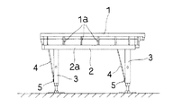
図1等において、1は、浴室ユニットとしての洗い場形成用の床パンである。この床パンは、図6〜図8に示されるように、外周面に補強用のリブ1aが格子状に形成されている。この実施形態に係る本発明は、このような浴室ユニット1としての床パンを載せる水平状の台座部2と、この台座部2の棒状の脚3とで形成されている。
Hereinafter, the best mode for carrying out the present invention will be described.
In FIG. 1 etc., 1 is the floor pan for washing-room formation as a bathroom unit. As shown in FIGS. 6 to 8, the floor pan has reinforcing
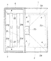
上記の台座部2は、図1、図2、図8等に示されるように、平行状に所定間隔をあけて配置された断面コの字形の短い鋼材2aと、この鋼材2aに直交して横方向にわたされ、接続箇所が溶接されると共に、平行状に所定間隔をあけて配置された角パイプ形の長い鋼材2bとで枠状に形成されている。脚3は、角材で形成されて台座部2の略四隅に、短い鋼材2aと長い鋼材2bの接続箇所からずらされて、短い鋼材2aの下面に設けられている。また脚3は、その下端に高さ調節用のアジャスターボルト3aが設けられている。
As shown in FIG. 1, FIG. 2, FIG. 8 and the like, the
4は、補強材である。この補強材4は、台座部2を形成する長い鋼材2bの側面と、脚3の設置面に近い先端部(下端部)に斜めにわたされて、この実施形態ではネジ5で取り付けられている。脚3は、上記の通り、台座部2の各鋼材2a、2bの接続箇所からずらされて配置されているから、補強材4の一端部4aが取り付けられる台座部2の取付面と、他端部4bが取り付けられる脚3の取付面とは、位置が前後にずらされている。
4 is a reinforcing material. The reinforcing
また補強材4は、例えばステンレス鋼等の金属材で細長い板状に形成され、この実施形態では全長が335mmに選定されている。またこの補強材4は、図4に示されるように、上記の各取付面にあてがわれる一端部4aと他端部4bとが平板状に形成され、且つこの一端部4aと他端部4bとの間の位置4cが、断面コの字形に屈曲形成されている。平板状の一端部4aと他端部4bの長さは、この実施形態では夫々40mmに選定されている。なお一端部4aと他端部4bには、ネジ孔4dが形成されている。
In addition, the reinforcing
本発明では補強材4を取り付ける台座部2と脚3の取付面が、上記の通り、前後にずらされている。そして補強材4は金属材で、一端部4aと他端部4bが平板状に形成されている。従って作業者は、補強材4の一端部4aと他端部4bを、手指や手動工具で取付面にぴったり合うよう適宜曲げ、その後、取付面にあてがってネジ5等で固定し組み立てる。
In the present invention, the mounting surfaces of the
次に請求項2に係る本発明品の好適な一実施形態を説明する。上例と同一箇所、同一部材については、同一の符号を付し、詳しい説明は省略する。
Next, a preferred embodiment of the product of the present invention according to
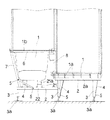
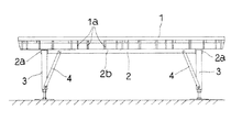
この本発明は、図1等に示されるように、浴室ユニット1としての浴槽を載せる水平状の台座部2と、この台座部2の上方に配置されて浴槽のフランジ部1bが係合される枠状の受け部材6と、この受け部材6を支持するため台座部2に起立状に設けられた支柱7とで形成されている。
In the present invention, as shown in FIG. 1 and the like, a
上記の台座部2は、図1、図2に示されるように、平行一対状のハット形鋼21と、このハット形鋼21と直交して横方向にわたされた平行一対状の角材22とで枠状に形成されている。ハット型鋼の端部は、角材22に載せられ、溶接されている。21aは、浴槽の脚載せ台である。浴槽は、図3に示されるように、この脚載せ台21aを介してハット形鋼21に載置される。なお台座部2を形成する角材22の一端は、浴室ユニット1としての床パンを支持する台座部2の脚3に溶接されている。従って浴室ユニット1としての浴槽を支持する台座部2は、角材22の他端にだけ脚3が設けられ、洗い場側は床パンを支持する台座部2の脚3を共用している。8は、エプロンである。支柱7は、角材22の端部に立設され、エプロン8と対向する側の隣り合う左右の支柱7は、筋かい9が交差状に設けられ、強度が高くなるよう形成されている。
As shown in FIGS. 1 and 2, the
4は、ステンレス鋼で細長い板状に形成された補強材である。この補強材4は、台座部2を形成する角材22と、支柱7に斜めにわたされてネジ5で取り付けられている。補強材4は、台座部2の取付面としての側面にあてがわれる一端部4aと、支柱7の取付面にあてがわれる他端部4bとが平板状に形成され、且つこの一端部4aと他端部4bとの間の位置4cが断面コの字形に屈曲形成されている。
而して作業者は、補強材4の一端部4aと他端部4bを適宜曲げ、支柱7と台座部2の取付面にぴったり合うよう微調整してネジ5で固定する。本発明の場合は、支柱7と台座部2に補強材4が斜めにわたされて設けられているから、支柱7に加わる横方向の揺れは、補強材4で抑えられ、ぐらつきが防止される。
Thus, the operator bends the one
以上の処において、本発明の場合、補強材4は、一端部4aと他端部4bが台座部2等の取付面の位置に合わせて当初から所定角度曲げられているのでも良い。また補強材4は、薄い板金には限られず、ワイヤー等の金属線材や、また弾性変形する合成樹脂材等でも良く、材料は任意である。また補強材4は、断面略コの字形に屈曲形成されている場合には限られず、例えばL字形、ハット形等の他の断面形状でも良く、また屈曲形成されず、全長にわたって平板状に形成されているのでも良い。
In the above place, in the case of the present invention, the reinforcing
また上例では、補強材4をネジ5で取り付けているが、本発明では例えば補強材4の一端だけがリベット等の締結部品で回転可能な状態で取り付けられ、他端は例えば施工現場で取り付け可能に形成されているのでも良い。この場合は、例えば脚3等も折り畳み可能に形成することで、台座部2の厚さを薄くできるから、嵩張りを防止でき、運搬や保管を容易化できる。
In the above example, the reinforcing
1 浴室ユニット
2 台座部
3 脚
4 補強材
1
Claims (5)
Priority Applications (1)
| Application Number | Priority Date | Filing Date | Title |
|---|---|---|---|
| JP2004104500A JP4590903B2 (en) | 2004-03-31 | 2004-03-31 | Support unit for bathroom unit and reinforcing material used therefor |
Applications Claiming Priority (1)
| Application Number | Priority Date | Filing Date | Title |
|---|---|---|---|
| JP2004104500A JP4590903B2 (en) | 2004-03-31 | 2004-03-31 | Support unit for bathroom unit and reinforcing material used therefor |
Related Child Applications (1)
| Application Number | Title | Priority Date | Filing Date |
|---|---|---|---|
| JP2010050502A Division JP2010163860A (en) | 2010-03-08 | 2010-03-08 | Support frame for bathroom unit |
Publications (2)
| Publication Number | Publication Date |
|---|---|
| JP2005290726A true JP2005290726A (en) | 2005-10-20 |
| JP4590903B2 JP4590903B2 (en) | 2010-12-01 |
Family
ID=35323975
Family Applications (1)
| Application Number | Title | Priority Date | Filing Date |
|---|---|---|---|
| JP2004104500A Expired - Fee Related JP4590903B2 (en) | 2004-03-31 | 2004-03-31 | Support unit for bathroom unit and reinforcing material used therefor |
Country Status (1)
| Country | Link |
|---|---|
| JP (1) | JP4590903B2 (en) |
Citations (8)
| Publication number | Priority date | Publication date | Assignee | Title |
|---|---|---|---|---|
| JPS54135033U (en) * | 1978-03-11 | 1979-09-19 | ||
| JPS56812U (en) * | 1979-06-15 | 1981-01-07 | ||
| JPS5761156A (en) * | 1980-09-29 | 1982-04-13 | Japan National Railway | Vibration proofing bed construction for building |
| JPH01284676A (en) * | 1988-05-10 | 1989-11-15 | Toto Ltd | Unit bathroom |
| JPH0318598U (en) * | 1990-07-09 | 1991-02-22 | ||
| JPH07317340A (en) * | 1994-05-25 | 1995-12-05 | Toto Ltd | Supporting frame for interior face bar of bath room |
| JP2003074193A (en) * | 2001-08-30 | 2003-03-12 | Ichiro Nagao | System construction method for seismic strengthening bracing for existing wooden building |
| JP2003210350A (en) * | 2002-01-23 | 2003-07-29 | Yamaha Livingtec Corp | Bathroom unit |
-
2004
- 2004-03-31 JP JP2004104500A patent/JP4590903B2/en not_active Expired - Fee Related
Patent Citations (8)
| Publication number | Priority date | Publication date | Assignee | Title |
|---|---|---|---|---|
| JPS54135033U (en) * | 1978-03-11 | 1979-09-19 | ||
| JPS56812U (en) * | 1979-06-15 | 1981-01-07 | ||
| JPS5761156A (en) * | 1980-09-29 | 1982-04-13 | Japan National Railway | Vibration proofing bed construction for building |
| JPH01284676A (en) * | 1988-05-10 | 1989-11-15 | Toto Ltd | Unit bathroom |
| JPH0318598U (en) * | 1990-07-09 | 1991-02-22 | ||
| JPH07317340A (en) * | 1994-05-25 | 1995-12-05 | Toto Ltd | Supporting frame for interior face bar of bath room |
| JP2003074193A (en) * | 2001-08-30 | 2003-03-12 | Ichiro Nagao | System construction method for seismic strengthening bracing for existing wooden building |
| JP2003210350A (en) * | 2002-01-23 | 2003-07-29 | Yamaha Livingtec Corp | Bathroom unit |
Also Published As
| Publication number | Publication date |
|---|---|
| JP4590903B2 (en) | 2010-12-01 |
Similar Documents
| Publication | Publication Date | Title |
|---|---|---|
| JP2015190256A (en) | wall-mounted toilet bowl | |
| JP2011098142A (en) | Table | |
| JP4590903B2 (en) | Support unit for bathroom unit and reinforcing material used therefor | |
| JP2010163860A (en) | Support frame for bathroom unit | |
| GB2232344A (en) | Improvements in or relating to a shelving arrangement | |
| JP2018084089A (en) | Corrugated floor support leg and corrugated floor structure using the same | |
| JP7468243B2 (en) | desk | |
| JP7179573B2 (en) | table | |
| JP6959881B2 (en) | Suspension stand and its manufacturing method | |
| JP6175667B1 (en) | Corrugated floor support leg and corrugated floor structure using the same | |
| WO2015098682A1 (en) | Load support member for furniture | |
| JPH0628048Y2 (en) | Chair | |
| JP6582346B2 (en) | Connection structure between support and upper plate in fixture with upper plate and fixture system with upper plate | |
| JP6452227B2 (en) | Handrail device | |
| KR200478238Y1 (en) | Seat Apparatus For Fishing | |
| JP3075035U (en) | Combination shelf | |
| JP3164784U (en) | Clothes rack | |
| JP2024003572A (en) | Display panel stand device | |
| JP3049500U (en) | Planter stand | |
| JP2011206507A (en) | Handrail for nursing care | |
| JP6687340B2 (en) | Support leg | |
| JP2016113832A (en) | Handrail bracket | |
| JP2009106412A (en) | Leg equipment for furniture such as chairs | |
| KR20140004388A (en) | Bench chair | |
| KR101571512B1 (en) | the frame for bench |
Legal Events
| Date | Code | Title | Description |
|---|---|---|---|
| A621 | Written request for application examination |
Free format text: JAPANESE INTERMEDIATE CODE: A621 Effective date: 20070323 |
|
| A977 | Report on retrieval |
Free format text: JAPANESE INTERMEDIATE CODE: A971007 Effective date: 20091224 |
|
| A131 | Notification of reasons for refusal |
Free format text: JAPANESE INTERMEDIATE CODE: A131 Effective date: 20100112 |
|
| A521 | Request for written amendment filed |
Free format text: JAPANESE INTERMEDIATE CODE: A523 Effective date: 20100308 |
|
| TRDD | Decision of grant or rejection written | ||
| A01 | Written decision to grant a patent or to grant a registration (utility model) |
Free format text: JAPANESE INTERMEDIATE CODE: A01 Effective date: 20100817 |
|
| A01 | Written decision to grant a patent or to grant a registration (utility model) |
Free format text: JAPANESE INTERMEDIATE CODE: A01 |
|
| A61 | First payment of annual fees (during grant procedure) |
Free format text: JAPANESE INTERMEDIATE CODE: A61 Effective date: 20100830 |
|
| FPAY | Renewal fee payment (event date is renewal date of database) |
Free format text: PAYMENT UNTIL: 20130924 Year of fee payment: 3 |
|
| R150 | Certificate of patent or registration of utility model |
Ref document number: 4590903 Country of ref document: JP Free format text: JAPANESE INTERMEDIATE CODE: R150 Free format text: JAPANESE INTERMEDIATE CODE: R150 |
|
| R250 | Receipt of annual fees |
Free format text: JAPANESE INTERMEDIATE CODE: R250 |
|
| R250 | Receipt of annual fees |
Free format text: JAPANESE INTERMEDIATE CODE: R250 |
|
| R250 | Receipt of annual fees |
Free format text: JAPANESE INTERMEDIATE CODE: R250 |
|
| R250 | Receipt of annual fees |
Free format text: JAPANESE INTERMEDIATE CODE: R250 |
|
| R250 | Receipt of annual fees |
Free format text: JAPANESE INTERMEDIATE CODE: R250 |
|
| R250 | Receipt of annual fees |
Free format text: JAPANESE INTERMEDIATE CODE: R250 |
|
| R250 | Receipt of annual fees |
Free format text: JAPANESE INTERMEDIATE CODE: R250 |
|
| R250 | Receipt of annual fees |
Free format text: JAPANESE INTERMEDIATE CODE: R250 |
|
| LAPS | Cancellation because of no payment of annual fees |