JP2005290714A - Check dam raising method for check dam - Google Patents
Check dam raising method for check dam Download PDFInfo
- Publication number
- JP2005290714A JP2005290714A JP2004104079A JP2004104079A JP2005290714A JP 2005290714 A JP2005290714 A JP 2005290714A JP 2004104079 A JP2004104079 A JP 2004104079A JP 2004104079 A JP2004104079 A JP 2004104079A JP 2005290714 A JP2005290714 A JP 2005290714A
- Authority
- JP
- Japan
- Prior art keywords
- check dam
- sabo dam
- concrete
- dam
- existing
- Prior art date
- Legal status (The legal status is an assumption and is not a legal conclusion. Google has not performed a legal analysis and makes no representation as to the accuracy of the status listed.)
- Granted
Links
- 238000000034 method Methods 0.000 title claims abstract description 20
- 238000004062 sedimentation Methods 0.000 claims abstract description 10
- 238000011144 upstream manufacturing Methods 0.000 claims abstract description 10
- XLYOFNOQVPJJNP-UHFFFAOYSA-N water Substances O XLYOFNOQVPJJNP-UHFFFAOYSA-N 0.000 claims description 5
- 210000004283 incisor Anatomy 0.000 claims description 2
- 238000005553 drilling Methods 0.000 claims 1
- 239000004576 sand Substances 0.000 claims 1
- 238000004321 preservation Methods 0.000 abstract 1
- 238000010276 construction Methods 0.000 description 8
- 238000006243 chemical reaction Methods 0.000 description 5
- 238000010586 diagram Methods 0.000 description 5
- 230000006835 compression Effects 0.000 description 3
- 238000007906 compression Methods 0.000 description 3
- 230000007613 environmental effect Effects 0.000 description 3
- 239000013049 sediment Substances 0.000 description 3
- 230000005484 gravity Effects 0.000 description 2
- 230000003014 reinforcing effect Effects 0.000 description 2
- 229910000831 Steel Inorganic materials 0.000 description 1
- 238000009412 basement excavation Methods 0.000 description 1
- 230000010354 integration Effects 0.000 description 1
- 238000007726 management method Methods 0.000 description 1
- 239000000463 material Substances 0.000 description 1
- 238000012986 modification Methods 0.000 description 1
- 230000004048 modification Effects 0.000 description 1
- 238000003541 multi-stage reaction Methods 0.000 description 1
- 238000009418 renovation Methods 0.000 description 1
- 239000010959 steel Substances 0.000 description 1
Images

Landscapes
- Working Measures On Existing Buildindgs (AREA)
- Revetment (AREA)
Abstract
Description
本発明は、既設の砂防ダムの嵩上げ方法に関する。 The present invention relates to a method for raising an existing sabo dam.
重力式コンクリート型式の砂防ダムの高さは、施工計画時の堆砂面の高さによって決定される。したがって、施工後に計画堆砂面の高さが上昇した場合には、新たに計画された堆砂面に対処しなければならない。従来、このような場合には、新規に砂防ダムを建設するか、或いは、新計画堆砂面に適合するように既設の砂防ダムを嵩上げしていた。 The height of the gravity concrete type sabo dam is determined by the height of the sedimentation surface at the time of construction planning. Therefore, if the height of the planned sedimentation surface increases after construction, the newly planned sedimentation surface must be dealt with. Conventionally, in such a case, a new sabo dam has been constructed or the existing sabo dam has been raised so as to conform to the newly planned sedimentation surface.
既設の砂防ダムの嵩上げは、嵩上げに要する堤体積に比べて新たに堆積可能な開発容積が大きいため、新規の砂防ダムを建設するよりも効率的な方法であるが、以下のような課題を有している。
(1)既設の砂防ダムの上流側にコンクリート体を施工するには、堆積土砂を除去する必要があるため、施工が困難である。
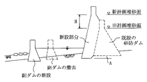
(2)既設の砂防ダムの下流側にコンクリート体を施工するには、砂防ダムが設けられている個所は一般的に河川が急勾配である場合が多いため、堤体断面が下流下がりな不安定な形状となる場合がある(図3においてAで図示)が、そのような場合は、堤体の体積が大きくなるうえ、施工時(特に直下流の掘削時)の安全性を確保する必要がある。
(3)減勢工長が不足し、減勢工の全面的な改修工事が発生するため、河道内の工事が多くなり、大規模な河流処理や土工を伴い、周囲環境に及ぼす影響が大きい(図3参照)。
(4)既設の砂防ダムにおいて頂部コンクリートを打継ぎして嵩上げすると、上流側に引張応力が発生するため、構造安全上問題がある。
Raising the existing sabo dam is a more efficient method than constructing a new sabo dam because the development volume that can be newly deposited is larger than the volume of the bank required for raising the dam, but the following issues are encountered: Have.
(1) In order to construct a concrete body on the upstream side of an existing sabo dam, it is necessary to remove the sediment, so construction is difficult.
(2) In order to construct a concrete body downstream of an existing sabo dam, the section where the sabo dam is installed generally has a steep river. In some cases, the shape may be stable (shown as A in FIG. 3). In such a case, the volume of the levee body becomes large, and it is necessary to ensure safety during construction (especially during excavation directly downstream). There is.
(3) Since there is a shortage of de-energizing chiefs and full-scale renovation work of de-energizing works occurs, there is a lot of construction in the river channel, which involves large-scale river flow treatment and earthwork, and has a large impact on the surrounding environment. (See FIG. 3).
(4) When the top concrete is cast and raised in an existing sabo dam, tensile stress is generated on the upstream side, which causes structural safety problems.
一方、新規の砂防ダムを建設すると、上述のような経済上の問題の他、ダム建設個所までのアクセス道路が必要になる等、環境保全上の課題も発生する。
このような状況下において、施工性、安全性、環境保全性等の課題を克服した砂防ダムの改修方法が望まれている。
On the other hand, when a new sabo dam is constructed, there are problems in environmental conservation, such as the need for an access road to the dam construction site, in addition to the economic problems described above.
Under such circumstances, a method for repairing a sabo dam that overcomes problems such as workability, safety, and environmental conservation is desired.
したがって、本発明は、従来技術における施工性、安全性、環境保全性等の課題を克服した既設の砂防ダムの嵩上げ方法を提供することを目的としている。 Accordingly, an object of the present invention is to provide a method for raising an existing sabo dam that overcomes problems such as workability, safety, and environmental conservation in the prior art.
本願請求項1に記載の砂防ダムの嵩上げ方法は、嵩上げしようとする既設の砂防ダムの袖部を取り壊す第1工程と、前記砂防ダムの下流側の傾斜面に差し筋など新旧コンクリートの一体化を施した後、面がほぼ垂直になるようにコンクリートを打設する第2工程と、前記砂防ダムの頂部から上流側の基礎地盤に向かって斜めボーリングを行い、ボーリング孔内に緊張部材を挿入して基礎地盤で固定した後、新計画堆砂圧によって生ずる引張力をほぼ打ち消す程の大きさの引張力を緊張部材に加える第3工程と、新計画堆砂面を確保するように前記砂防ダムの上部にコンクリートを打設する第4工程とを含むことを特徴とするものである。 The method for raising a sabo dam according to claim 1 of the present invention is the first step of demolishing the sleeve portion of an existing sabo dam to be raised, and the integration of old and new concrete such as incisors on the inclined surface downstream of the sabo dam. After the second step, the concrete is placed so that the surface is almost vertical, and the boring is performed obliquely from the top of the sabo dam toward the upstream foundation ground, and a tension member is inserted into the borehole. Then, after fixing on the foundation ground, the third step of applying a tensile force to the tension member to a magnitude that almost cancels the tensile force generated by the newly planned sediment pressure, and the sabo to secure the newly planned sediment surface And a fourth step of placing concrete on top of the dam.
本願請求項2に記載の砂防ダムの嵩上げ方法は、前記請求項1の方法において、前記第4工程の後、前記砂防ダムの下流側の底部に水叩き保護部を設ける工程を更に含むことを特徴とするものである。 The method for raising a sabo dam according to claim 2 of the present application further includes a step of providing a water hitting protection part at the bottom of the sabo dam downstream of the fourth step in the method of claim 1. It is a feature.
本発明によれば、既設のダム堤敷内での施工が主体となり、減勢工などダムの下流側への影響が大幅に削減されるため、コスト低減を図ることができるとともに、環境保全上からも有利である。また、頂部コンクリートを打継ぎして嵩上げしても、上流側に引張応力が生じないため、構造上も有利である。 According to the present invention, construction is mainly performed in the existing dam dam, and the influence on the downstream side of the dam, such as de-energization work, is greatly reduced. Is also advantageous. Further, even if the top concrete is cast and raised, no tensile stress is generated on the upstream side, which is advantageous in terms of structure.
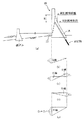
次に図面を参照して、本発明の好ましい実施の形態に係る砂防ダムの嵩上げ方法について詳細に説明する。まず、嵩上げしようとする既設の砂防ダム10(長破線で図示)の袖部10aを取り壊す(図1(b)参照)。次いで、既設の砂防ダム10の下流側の下部施工を行う。具体的には、既設の砂防ダム10の下流側の傾斜面に差し筋12など新旧コンクリートの一体化を施した後、傾斜面がほぼ垂直になるようにコンクリート14を打設する(図1(c)参照)。これにより、後述する斜めボーリング作業や緊張作業を行うためのスペース(コンクリート14の上面)が確保される。
Next, a method for raising a sabo dam according to a preferred embodiment of the present invention will be described in detail with reference to the drawings. First, the
次いで、既設の砂防ダム10の頂部から上流側の基礎地盤に向かって斜めボーリングを行い、ボーリング孔内にPC鋼材などの緊張部材16を挿入し、基礎地盤で固定した後、緊張部材16に引張力を加える(図1(d)参照)。緊張部材16に加える引張力は、新計画堆砂圧によって生ずる引張力をほぼ打ち消す程の大きさとする。
Next, oblique boring is performed from the top of the existing
次いで、新計画堆砂面を確保すべく、既設の砂防ダム10の上部にコンクリート18を打設する(図1(e)参照)。
Next,
以上のようにして、嵩上げした砂防ダム20が完成する(図1(f)参照)。なお、嵩上げした砂防ダム20の下部は、上流側が既設の勾配のままであり、下流側がほぼ垂直な勾配となる。また、砂防ダム20の上部は、重力式コンクリート型式として所要の安全性を確保できるような形状とする。
The raised
図2は、本発明の嵩上げ方法を施した砂防ダム20の全体図、並びに、砂防ダム20の底面における反力を示した図である。すなわち、図2(b)は、既設の砂防ダムの旧計画堆砂圧による反力図(下流側:圧縮力C1 )、図2(c)は、嵩上げした砂防ダム20の新計画堆砂圧による反力図(下流側:圧縮力C2 、上流側:T1 )、図2(d)は、緊張部材16の引張力による反力図(上流側:圧縮力C3 ≒T1 )、図2(e)は、嵩上げした砂防ダム20の合成反力図(下流側:圧縮力C4 =C1 +C2 )である。図2(e)から分かるように、砂防ダム20の底面においては引張力は生じない。
FIG. 2 is an overall view of the
なお、嵩上げした砂防ダム20においては、減勢方式が自由落下に近い形状になるため、砂防ダム20の下流側の底部に、水叩き保護部22を設けるのが好ましい場合がある。水叩き保護部22としては、コンクリート塊、ブロックなどが用いられる。
In addition, in the raised
また、管理上、緊張部材16に再緊張作業を伴う場合には、緊張部材16の上部延長上に作業孔を設置することにより作業可能となる。
In addition, for management purposes, when the
本発明は、以上の発明の実施の形態に限定されることなく、特許請求の範囲に記載された発明の範囲内で、種々の変更が可能であり、それらも本発明の範囲内に包含されるものであることはいうまでもない。 The present invention is not limited to the above-described embodiments, and various modifications can be made within the scope of the invention described in the claims, and these are also included in the scope of the present invention. Needless to say, it is something.
10 既設の砂防ダム
10a 袖部
12 差し筋
14 下部コンクリート
16 緊張部材
18 上部コンクリート
20 嵩上げされた砂防ダム
22 水叩き保護部
DESCRIPTION OF
Claims (2)
嵩上げしようとする既設の砂防ダムの袖部を取り壊す第1工程と、
前記砂防ダムの下流側の傾斜面に差し筋など新旧コンクリートの一体化を施した後、面がほぼ垂直になるようにコンクリートを打設する第2工程と、
前記砂防ダムの頂部から上流側の基礎地盤に向かって斜めボーリングを行い、ボーリング孔内に緊張部材を挿入して基礎地盤で固定した後、新計画堆砂圧によって生ずる引張力をほぼ打ち消す程の大きさの引張力を緊張部材に加える第3工程と、
新計画堆砂面を確保するように前記砂防ダムの上部にコンクリートを打設する第4工程と、
を含むことを特徴とする方法。 A method for raising a sabo dam,
A first step of demolishing a sleeve of an existing sabo dam to be raised;
A second step of placing the concrete so that the surface is substantially vertical after integrating the old and new concrete, such as incisors, on the inclined surface on the downstream side of the sabo dam;
After drilling diagonally from the top of the sabo dam toward the upstream foundation ground, inserting a tension member into the borehole and fixing it with the foundation ground, the tensile force generated by the newly planned sedimentation pressure is almost canceled. A third step of applying a tensile force of magnitude to the tension member;
A fourth step of placing concrete on top of the sabo dam so as to secure the newly planned sand surface;
A method comprising the steps of:
Priority Applications (1)
| Application Number | Priority Date | Filing Date | Title |
|---|---|---|---|
| JP2004104079A JP4204504B2 (en) | 2004-03-31 | 2004-03-31 | Raising the sabo dam |
Applications Claiming Priority (1)
| Application Number | Priority Date | Filing Date | Title |
|---|---|---|---|
| JP2004104079A JP4204504B2 (en) | 2004-03-31 | 2004-03-31 | Raising the sabo dam |
Publications (2)
| Publication Number | Publication Date |
|---|---|
| JP2005290714A true JP2005290714A (en) | 2005-10-20 |
| JP4204504B2 JP4204504B2 (en) | 2009-01-07 |
Family
ID=35323963
Family Applications (1)
| Application Number | Title | Priority Date | Filing Date |
|---|---|---|---|
| JP2004104079A Expired - Fee Related JP4204504B2 (en) | 2004-03-31 | 2004-03-31 | Raising the sabo dam |
Country Status (1)
| Country | Link |
|---|---|
| JP (1) | JP4204504B2 (en) |
Cited By (2)
| Publication number | Priority date | Publication date | Assignee | Title |
|---|---|---|---|---|
| JP2020094377A (en) * | 2018-12-12 | 2020-06-18 | 一般財団法人砂防フロンティア整備推進機構 | Method of making slit in drainage culvert, and erosion control dam having drainage culvert |
| CN112813931A (en) * | 2021-02-05 | 2021-05-18 | 中国电建集团华东勘测设计研究院有限公司 | Heightening mixed dam structure combined with built earth-rock dam and construction method thereof |
-
2004
- 2004-03-31 JP JP2004104079A patent/JP4204504B2/en not_active Expired - Fee Related
Cited By (3)
| Publication number | Priority date | Publication date | Assignee | Title |
|---|---|---|---|---|
| JP2020094377A (en) * | 2018-12-12 | 2020-06-18 | 一般財団法人砂防フロンティア整備推進機構 | Method of making slit in drainage culvert, and erosion control dam having drainage culvert |
| JP7194576B2 (en) | 2018-12-12 | 2022-12-22 | 一般財団法人砂防フロンティア整備推進機構 | Slitting method for drainage culvert and Sabo dam having the drainage culvert |
| CN112813931A (en) * | 2021-02-05 | 2021-05-18 | 中国电建集团华东勘测设计研究院有限公司 | Heightening mixed dam structure combined with built earth-rock dam and construction method thereof |
Also Published As
| Publication number | Publication date |
|---|---|
| JP4204504B2 (en) | 2009-01-07 |
Similar Documents
| Publication | Publication Date | Title |
|---|---|---|
| CN104405403B (en) | A kind of control tunneling greatly across the construction method of subway station surrouding rock deformation | |
| JP6936613B2 (en) | Masonry reinforcement structure and reinforcement method | |
| JP5274145B2 (en) | Cast-in-place pile and its construction method | |
| CN102162255A (en) | Method for reinforcing existing pile foundation in collapsed loess area by slip casting | |
| EA031926B1 (en) | Method for forming a pillar part and reinforcing adjacently constructed parallel tunnels with reinforcing rods | |
| CN109235490B (en) | Retaining wall and its construction method | |
| CN105862862B (en) | A kind of large diameter pile buries hammer Refloatation method | |
| JP2009235809A (en) | Construction method for dismantlement and removal of underground structure having foundation pile | |
| KR101109520B1 (en) | Construction method of soil barrier using steel pipe pile | |
| CN104775433A (en) | Pile extracting construction method | |
| CN106812131B (en) | A kind of permanent sheet pile underground structure and its construction method | |
| KR100898969B1 (en) | Tunnel excavation method using sheet pile and tunnel structure | |
| JP4373824B2 (en) | Joining method of cast-in-place pile and steel pipe column | |
| Shong et al. | Design & construction of micropiles | |
| JP4204504B2 (en) | Raising the sabo dam | |
| JP2000170149A (en) | Forming method for underground pile and equipment therefor | |
| CN116220733B (en) | Internal anchoring combined protection technology for lower existing tunnel under top unloading | |
| Porterfield et al. | Soil nailing field inspectors manual-soil nail walls | |
| CN100557144C (en) | A Method for Removing Construction Obstacles of Bored Pile | |
| CN107747315A (en) | A kind of recycling method of shaped steel component for pattern foundation pit supporting structure | |
| KR20130002797A (en) | Reinforced concrete pile construction method for which steel pipe casing structure for steel pipe casing recovery this were used | |
| CN104018492A (en) | Bamboo reinforced concrete pile | |
| Lajer et al. | Deep foundation for high rise in tricky soil conditions and surroundings in Scandinavia–Walkthrough of various high‐rise projects from initial geology to final execution and everything in between | |
| JP2006348690A (en) | Retrofitting method for base isolation of existing building | |
| JP2015101880A (en) | Structure of retaining wall and construction method for the same |
Legal Events
| Date | Code | Title | Description |
|---|---|---|---|
| A621 | Written request for application examination |
Free format text: JAPANESE INTERMEDIATE CODE: A621 Effective date: 20070207 |
|
| A977 | Report on retrieval |
Free format text: JAPANESE INTERMEDIATE CODE: A971007 Effective date: 20080812 |
|
| A131 | Notification of reasons for refusal |
Free format text: JAPANESE INTERMEDIATE CODE: A131 Effective date: 20080829 |
|
| A521 | Request for written amendment filed |
Free format text: JAPANESE INTERMEDIATE CODE: A523 Effective date: 20080908 |
|
| TRDD | Decision of grant or rejection written | ||
| A01 | Written decision to grant a patent or to grant a registration (utility model) |
Free format text: JAPANESE INTERMEDIATE CODE: A01 Effective date: 20081001 |
|
| A01 | Written decision to grant a patent or to grant a registration (utility model) |
Free format text: JAPANESE INTERMEDIATE CODE: A01 |
|
| A61 | First payment of annual fees (during grant procedure) |
Free format text: JAPANESE INTERMEDIATE CODE: A61 Effective date: 20081014 |
|
| FPAY | Renewal fee payment (event date is renewal date of database) |
Free format text: PAYMENT UNTIL: 20111024 Year of fee payment: 3 |
|
| R150 | Certificate of patent or registration of utility model |
Ref document number: 4204504 Country of ref document: JP Free format text: JAPANESE INTERMEDIATE CODE: R150 |
|
| FPAY | Renewal fee payment (event date is renewal date of database) |
Free format text: PAYMENT UNTIL: 20111024 Year of fee payment: 3 |
|
| FPAY | Renewal fee payment (event date is renewal date of database) |
Free format text: PAYMENT UNTIL: 20141024 Year of fee payment: 6 |
|
| R250 | Receipt of annual fees |
Free format text: JAPANESE INTERMEDIATE CODE: R250 |
|
| R250 | Receipt of annual fees |
Free format text: JAPANESE INTERMEDIATE CODE: R250 |
|
| R250 | Receipt of annual fees |
Free format text: JAPANESE INTERMEDIATE CODE: R250 |
|
| R250 | Receipt of annual fees |
Free format text: JAPANESE INTERMEDIATE CODE: R250 |
|
| LAPS | Cancellation because of no payment of annual fees |