JP2005290664A - Block for retaining wall, and retaining wall using it - Google Patents
Block for retaining wall, and retaining wall using it Download PDFInfo
- Publication number
- JP2005290664A JP2005290664A JP2004102465A JP2004102465A JP2005290664A JP 2005290664 A JP2005290664 A JP 2005290664A JP 2004102465 A JP2004102465 A JP 2004102465A JP 2004102465 A JP2004102465 A JP 2004102465A JP 2005290664 A JP2005290664 A JP 2005290664A
- Authority
- JP
- Japan
- Prior art keywords
- wall
- retaining wall
- block
- water
- retaining
- Prior art date
- Legal status (The legal status is an assumption and is not a legal conclusion. Google has not performed a legal analysis and makes no representation as to the accuracy of the status listed.)
- Granted
Links
- XLYOFNOQVPJJNP-UHFFFAOYSA-N water Substances O XLYOFNOQVPJJNP-UHFFFAOYSA-N 0.000 claims abstract description 86
- 239000000463 material Substances 0.000 claims description 18
- 238000010521 absorption reaction Methods 0.000 claims description 5
- 239000004568 cement Substances 0.000 claims description 5
- 239000002689 soil Substances 0.000 abstract description 12
- 238000000034 method Methods 0.000 description 9
- 241000196324 Embryophyta Species 0.000 description 7
- 238000010276 construction Methods 0.000 description 4
- 238000001723 curing Methods 0.000 description 4
- 230000000717 retained effect Effects 0.000 description 4
- 239000000835 fiber Substances 0.000 description 3
- 238000009434 installation Methods 0.000 description 3
- 238000004519 manufacturing process Methods 0.000 description 3
- 239000002969 artificial stone Substances 0.000 description 2
- 238000005056 compaction Methods 0.000 description 2
- 239000000428 dust Substances 0.000 description 2
- 239000004744 fabric Substances 0.000 description 2
- 239000003337 fertilizer Substances 0.000 description 2
- 230000035784 germination Effects 0.000 description 2
- 241000609240 Ambelania acida Species 0.000 description 1
- 235000013162 Cocos nucifera Nutrition 0.000 description 1
- 244000060011 Cocos nucifera Species 0.000 description 1
- BZHJMEDXRYGGRV-UHFFFAOYSA-N Vinyl chloride Chemical compound ClC=C BZHJMEDXRYGGRV-UHFFFAOYSA-N 0.000 description 1
- 239000000853 adhesive Substances 0.000 description 1
- 230000001070 adhesive effect Effects 0.000 description 1
- 239000010905 bagasse Substances 0.000 description 1
- 238000011109 contamination Methods 0.000 description 1
- 238000007599 discharging Methods 0.000 description 1
- 238000001035 drying Methods 0.000 description 1
- 238000005516 engineering process Methods 0.000 description 1
- 239000003673 groundwater Substances 0.000 description 1
- 238000000465 moulding Methods 0.000 description 1
- 229910001562 pearlite Inorganic materials 0.000 description 1
- 230000035699 permeability Effects 0.000 description 1
- 239000000049 pigment Substances 0.000 description 1
- 230000003014 reinforcing effect Effects 0.000 description 1
- 239000011347 resin Substances 0.000 description 1
- 229920005989 resin Polymers 0.000 description 1
- 239000007787 solid Substances 0.000 description 1
- 230000005068 transpiration Effects 0.000 description 1
Images


Landscapes
- Retaining Walls (AREA)
Abstract
Description
本発明は、擁壁用ブロックおよびそれを用いた擁壁に関する。 The present invention relates to a retaining wall block and a retaining wall using the same.
従来、道路わきの擁壁等は、コンクリート製の積みブロックを積み重ねることによって構築される場合が多い。この場合の道路わきの法面に擁壁を構築する方法は、法面の傾斜に合わせて積みブロックを積み重ねていき、積みブロックと法面を有する地盤の間の空隙内に裏込めコンクリートを流し込んでいる。しかしながら、地盤中に雨水が浸透すると、土圧の増加によって、擁壁等が崩壊する恐れがあった。 Conventionally, a roadside retaining wall and the like are often constructed by stacking concrete building blocks. In this case, the method of building the retaining wall on the slope of the roadside is to stack the building blocks according to the slope of the slope, and to pour the backfill concrete into the gap between the building block and the ground with the slope. It is out. However, when rainwater penetrates into the ground, the retaining wall and the like may collapse due to an increase in earth pressure.
そのため、例えば、積みブロック自体に水抜き用の孔を設けていたり(例えば、特許文献1参照)、ブロック同士の間に水抜き用の孔を設けたり(例えば、特許文献2参照)して、この孔から地盤中の水を排水させることによって土圧の増加を防いでいる。 Therefore, for example, a hole for draining is provided in the stacking block itself (for example, see Patent Document 1), or a hole for draining is provided between the blocks (for example, see Patent Document 2), The earth pressure is prevented from increasing by draining the ground water from this hole.
一方で、コンクリート製の擁壁は、堅固な法面を構成することで土砂崩れ等の被害対策には非常に有効である。しかしながらその反面、景観上や、生態系の保全等の面からは好ましくないという問題点があった。 On the other hand, the retaining wall made of concrete is very effective for countermeasures against damage such as landslides by forming a solid slope. However, on the other hand, there is a problem that it is not preferable in terms of landscape and ecosystem conservation.
そのため、積みブロックの内部に空間部(植栽部)を設け、その空間に植栽用の土を充填し、そこに植物等を植栽したりして、景観性の向上や生態系の保全を図っている(例えば、特許文献3参照)。この場合、植栽部に保水されるそれ以上の水が流入して来た場合は、植栽部底部に設けられた水抜き孔によって下段のブロックの植栽部に導かれるような技術も開発されている(例えば、特許文献4参照)
しかしながら、積みブロック自体に水抜き用の孔を設けていたり、ブロック同士の間に水抜き用の孔を設けたりする方法では、土中の水は該水抜き用の孔によって擁壁前面に排出されブロック表面を流れ落ちるので、水が通った跡は汚くなるという問題点がある。 However, if the stacking block itself has a drain hole or a drain hole between the blocks, the water in the soil is discharged to the front of the retaining wall through the drain hole. Since it flows down the block surface, there is a problem that the traces of water passing through become dirty.
一方で、植栽部を設けて植栽する方法では、植栽部に充填された土に保水される水の量には限界があり、降雨が長期間なかったり、高温が続いたりした場合には、植物が枯死して景観上見苦しいという問題点がある。
また、保水される以上の水が流入した場合は、オーバーフローして植栽部から溢れブロック前面から流れ落ち、上述のようなブロック前面の汚濁を起こすという問題点もある。
On the other hand, in the method of planting by providing a planting part, there is a limit to the amount of water retained in the soil filled in the planting part, when there is no rainfall for a long period of time or high temperature continues However, there is a problem that the plants die and the landscape is unsightly.
In addition, when more water than the water that can be retained flows in, it overflows from the planting part and flows down from the front surface of the block, causing the above-described contamination of the front surface of the block.
本発明は、上記従来技術の問題点に鑑みてなされたもので、水抜き用の孔によって排出される水をブロック前面を流れることなく擁壁外へ排出されるとともに、この排出される水を植栽部へ誘導することによって、人為的な強制的な植栽を避け自然に植栽可能な植栽部を有する擁壁及び該擁壁を構築するための擁壁用ブロックを提供することを課題とする。 The present invention has been made in view of the above-mentioned problems of the prior art. The water discharged by the drain hole is discharged outside the retaining wall without flowing through the front surface of the block. Providing a retaining wall having a planting part that can be planted naturally by avoiding artificially forced planting by guiding to the planting part, and a retaining wall block for constructing the retaining wall Let it be an issue.
本発明者らは、上記課題を解決するために鋭意検討した結果、ブロック側面の一部に水みちを設けること、および該水みちの途中に植栽部と成り得る空間を設けることによって、擁壁背後の土中の水をブッロク前面を通さずに擁壁外へ排出されるとともに、自然に従った植栽が可能となることを見出し、本発明を完成した。 As a result of intensive studies to solve the above problems, the present inventors have provided a water channel in a part of the side surface of the block, and provided a space that can be a planting part in the middle of the water channel. It was found that the water in the soil behind the wall was discharged out of the retaining wall without passing through the front of the block, and planting according to nature became possible, and the present invention was completed.
すなわち、前壁、中間壁、中間壁に取り付けられている控え部材とから構成される擁壁用ブロックにおいて、中間壁前部頂部と中間壁前部と中間壁後部とから中間壁が構成されており、さらに前壁と中間壁との間に貯水可能な空間部を有することを特徴とする擁壁用ブロックである(請求項1)。
そして、地山から排出された水が前壁と中間壁との間の貯水可能な空間部へ誘導される構造を有することを特徴とする請求項1記載の擁壁用ブロックである(請求項2)。
さらに、前壁と中間壁との間の貯水可能な空間部から溢れ出した水が前壁と中間壁との間を通ってそれぞれ左右反対方向、又は一定の方向へ流れ出す構造を有することを特徴とする請求項1及び請求項2記載の擁壁用ブロック(請求項3)である。
次に、水抜き孔が控え部材中に設けられていて、該水抜き孔によって地山と前壁と中間壁との間の貯水可能な空間部とが連通していることを特徴とする請求項1、請求項2及び請求項3記載の擁壁用ブロックである(請求項4)。
そして、前壁が吸水率2〜20%のセメント系素材、またはポーラスコンクリートであることを特徴とする請求項1、請求項2、請求項3および請求項5記載の擁壁用ブロック
である(請求項5)。
そして、請求項1、請求項2、請求項3、請求項4または請求項5記載の擁壁用ブロックによって構成される擁壁において、前壁と中間壁との間の貯水可能な空間部から溢れ出した水が前壁と中間壁との間を通ってそれぞれ左右反対方向、又は一定の方向へ流れ出し、下段の擁壁用ブロックの前壁と中間壁との間の貯水可能な空間部へ流れ込み、更に余剰となった水は順次同様に流れ下り最下段から擁壁の外に排出される構造を有することを特徴とする擁壁である(請求項6)。
また、隣り合う擁壁用ブロックの中間壁前部と擁壁用ブロックの中間壁前部との間の空間に植栽部を設置することを特徴とする請求項6記載の擁壁である(請求項7)。
That is, in the retaining wall block composed of the front wall, the intermediate wall, and the retaining member attached to the intermediate wall, the intermediate wall is configured from the top of the intermediate wall, the front of the intermediate wall, and the rear of the intermediate wall. And a retaining wall block characterized by further comprising a space capable of storing water between the front wall and the intermediate wall (claim 1).
The retaining wall block according to
Furthermore, it has a structure in which water overflowing from the space where water can be stored between the front wall and the intermediate wall flows out between the front wall and the intermediate wall in the opposite left-right direction or in a certain direction. The retaining wall block according to
Next, a drainage hole is provided in the retaining member, and the drainage hole communicates with a natural mountain, a space portion capable of storing water between the front wall and the intermediate wall. The retaining wall block according to
The retaining wall block according to
And in the retaining wall comprised by the block for retaining walls of
7. The retaining wall according to
本発明による擁壁用ブロックおよび擁壁は、次の方法によって製造および構築される。
〔擁壁用ブロックの製造〕
本発明の擁壁用ブロックの製造方法は、特に限定されるものではなく、通常のコンクリート製品を製造する方法に従えば良い。
即ち、各材料を軽量し、ミキサーに投入・攪拌後、鉄筋等を配置した所定の型枠に充填し、流し込みによる振動締め固め、又は加圧ないし加圧振動締め固めを行う。養生方法は気中養生、蒸気養生の何れでも良い。養生後、脱型することによって、本発明の擁壁用ブロックを製造することができる。
The retaining wall block and retaining wall according to the present invention are manufactured and constructed by the following method.
[Manufacture of retaining wall blocks]
The method for producing the retaining wall block of the present invention is not particularly limited, and may be performed in accordance with a method for producing a normal concrete product.
That is, each material is reduced in weight, put into a mixer and stirred, and then filled into a predetermined mold in which reinforcing bars and the like are arranged, and vibration compaction by pouring or pressurization or pressure vibration compaction is performed. The curing method may be either air curing or steam curing. By removing the mold after curing, the retaining wall block of the present invention can be produced.
〔擁壁の構築〕
擁壁の構築は、特に限定されるものではなく、通常のコンクリート製擁壁を構築する方法に従えば良い。
すなわち、基礎コンクリート打設後、多数の擁壁用ブロックの側面を突き合わせて並列し、擁壁用ブロックの地山側に胴込め材料を充填しながら、順次段数を積み上げて施工して行き、最後に天端コンクリートを打設すれば良い。積み方としては、布積み、谷積み等いずれでも良い。
[Construction of retaining wall]
The construction of the retaining wall is not particularly limited, and a normal method for constructing a concrete retaining wall may be followed.
In other words, after placing the foundation concrete, the side surfaces of many retaining wall blocks are butted in parallel, and while filling the ground material side of the retaining wall block, the number of steps is piled up and then applied. You only need to cast the top concrete. As a stacking method, any of cloth stacking, valley stacking, etc. may be used.
〔植栽部の作成〕
植栽部は、水透過性材料、又は植生基盤から構成される。水透過性材料の例としては、塩化ビニル製やポリプロン製等からなる樹脂繊維、バガスや椰子殻繊維等からなる植物性繊維等から構成される水透過性を有するブロック状物や網目状物等がある。これらの形状は特に限定されるものではなく、布状、矩形状、三角形状、T字形状、球形状でも良い。植生基盤の例としては、肥料等を充填したポーラスコンクリート製ブロック、肥料等を混入したパーライト等をブロック化したもの等がある。これらの形状は特に限定されるものではなく、矩形状、三角形状、T字形状、球形状でも良い。
これらの水透過性材料、又は植生基盤を、隣り合う擁壁用ブロックの中間壁前部と擁壁用ブロックの中間壁前部との間の空間に設置することにより植栽部を作成することができる。設置方法は特に限定されるものではなく、補助具を使用して固定しても良く、前記空間に嵌め込んでも良いし、接着材等で擁壁用ブロックに接着しても良いし、T字形状のものを引っ掛けるだけでも良いし、隣り合う擁壁用ブロックの中間壁前部と擁壁用ブロックの中間壁前部とを跨ぐように設置しても良い。
[Create planting department]
A planting part is comprised from a water-permeable material or a vegetation base. Examples of water permeable materials include water-permeable blocks and meshes made of resin fibers made of vinyl chloride, polyprone, etc., plant fibers made of bagasse, coconut shell fibers, etc. There is. These shapes are not particularly limited, and may be a cloth shape, a rectangular shape, a triangular shape, a T shape, or a spherical shape. Examples of the vegetation base include a block made of porous concrete filled with fertilizer or the like, or a block of pearlite mixed with fertilizer or the like. These shapes are not particularly limited, and may be rectangular, triangular, T-shaped, or spherical.
Creating a planting part by installing these water-permeable materials or vegetation bases in the space between the intermediate wall front part of the adjacent retaining wall block and the intermediate wall front part of the retaining wall block Can do. The installation method is not particularly limited, and may be fixed using an auxiliary tool, may be fitted into the space, may be adhered to the retaining wall block with an adhesive, or the like, or T-shaped. You may just hook a shape, and you may install so that the intermediate wall front part of the block for adjacent retaining walls and the intermediate wall front part of the retaining wall block may be straddled.
従来、積みブロックにより構築された擁壁は、積みブロック前面に水抜き孔が存在し、このため該水抜き孔が擁壁全面に点在して景観を損ねているだけでなく、該水抜き孔から排出された擁壁背後の土中の水が積みブロック表面を通過した跡が汚く汚れて更に不快感を与えていた。
また、植栽部を設けた積みブロックによる擁壁の場合は、植栽部に充填された土等の保水量の制限や降雨が長期間なかった場合等を考慮せず、強制的に植栽を施したことにより前述の乾燥等により植物が枯死する場合があり、この場合は枯死した植物がそのまま存在するため著しく景観を損ない極めて不快感を与えていた。
Conventionally, a retaining wall constructed by a stacking block has a drainage hole on the front surface of the stacking block. Therefore, the drainage hole is not only scattered on the entire retaining wall, but also the landscape is damaged. The trace of the water in the soil behind the retaining wall discharged from the hole passing through the surface of the stacking block was dirty and dirty, giving further discomfort.
In addition, in the case of a retaining wall with a building block provided with a planting part, forcibly planting without considering the limitation of the amount of water retained by the soil filled in the planting part or when there has been no rainfall for a long period of time In some cases, the plant may die due to the above-mentioned drying or the like, and in this case, the dead plant exists as it is.
本発明の擁壁用ブロックによれば、擁壁用ブロックの側面に水みちができるように構成されている為、擁壁用ブロックの前面が水の通過によって汚れることもなく、また、自然の条件に合った場合のみ植栽が可能となるように構成されている為、過度の植栽による枯死をもたらすこともなく、極めて良好な景観を提供することができる。
さらに、擁壁用ブロック表面を擬石等で化粧した場合や表面にデザイン性をもたらすような装飾を施した場合は、上記水跡による汚れが発生しないため、良好な景観を維持し続けることができる。
According to the retaining wall block of the present invention, since the water wall is formed on the side surface of the retaining wall block, the front surface of the retaining wall block is not stained by the passage of water, Since it is configured so that planting is possible only when the conditions are met, an extremely good landscape can be provided without causing death due to excessive planting.
Furthermore, when the retaining wall block surface is decorated with artificial stones, or when the surface is decorated so as to bring about design, the above water marks do not cause dirt, so that a good landscape can be maintained. .
以下、本発明の擁壁用ブロックおよび該擁壁用ブロックによって構築された擁壁の一例を図面にしたがって説明する。
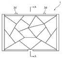
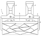
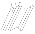
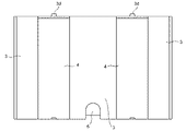
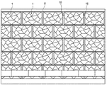
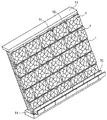
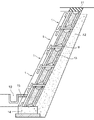
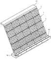
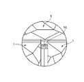
図1は本発明の擁壁用ブロックの一例の正面図、図2は図1の擁壁用ブロックの平面図、図3は図1の擁壁用ブロックの側面図、図4は図1の擁壁用ブロックの背面図、図5は図1の擁壁用ブロックのA−A断面図、図6は図1の擁壁用ブロックの斜視図、図7は図1の擁壁用ブロックの背後からの斜視図、図8は図1の擁壁用ブロックの前壁を取り除いたときの斜視図、図9は図1の擁壁用ブロックを用いて構築した擁壁の一例およびその周囲を示す正面図、図10は図9の擁壁の斜視図、図11は図9の擁壁の断面図、図12は本発明の擁壁用ブロックの更なる他の例を示す擁壁用ブロックの斜視図、図13は図12の擁壁用ブロックの背後からの斜視図、図14は図12の擁壁用ブロックの断面図、図15は図12の擁壁用ブロックを用いて構築した擁壁の一例およびその周囲を示す斜視図である。図16は図9の植栽部設置部分付近の部分拡大図である。
Hereinafter, an example of a retaining wall block according to the present invention and a retaining wall constructed by the retaining wall block will be described with reference to the drawings.
1 is a front view of an example of a retaining wall block of the present invention, FIG. 2 is a plan view of the retaining wall block of FIG. 1, FIG. 3 is a side view of the retaining wall block of FIG. FIG. 5 is a cross-sectional view of the retaining wall block taken along line AA in FIG. 1, FIG. 6 is a perspective view of the retaining wall block in FIG. 1, and FIG. 7 is a perspective view of the retaining wall block in FIG. FIG. 8 is a perspective view when the front wall of the retaining wall block of FIG. 1 is removed, and FIG. 9 is an example of a retaining wall constructed using the retaining wall block of FIG. FIG. 10 is a perspective view of the retaining wall of FIG. 9, FIG. 11 is a sectional view of the retaining wall of FIG. 9, and FIG. 12 is a retaining wall block showing still another example of the retaining wall block of the present invention. 13 is a perspective view from behind the retaining wall block of FIG. 12, FIG. 14 is a sectional view of the retaining wall block of FIG. 12, and FIG. 15 is a sectional view of the retaining wall block of FIG. Is a perspective view showing one example and around the retaining wall constructed in this household. FIG. 16 is a partially enlarged view in the vicinity of the planting part installation part of FIG. 9.
本発明の擁壁用ブロック1は、図1〜図8、図12〜図14に示すように、擁壁用ブロックの施工後に露出面となる前面を有する前壁2と、前壁2の裏面側に設けられる中間壁3と、中間壁3の裏面側に取り付けられる控え部材4とから構成される擁壁用ブロックである。
As shown in FIGS. 1 to 8 and 12 to 14, the retaining
前壁2は、水平方向の幅が中間壁後部3cと同じ幅でも、一回り小さい幅でも良い。ただし、擁壁が前面側に湾曲している場合には一回り小さい幅の方が施工しやすいため好ましい。
The
また、前壁2の前面(表面)は、擁壁用ブロックの美観を向上させるために、複数の幾何学的な形状となる起伏を設けたり、顔料等で着色したり、天然石や擬石を任意に配置したり、またこれらを複数組合わせても良い。幾何学的な形状となる起伏を設けた例を図6及び図12に示してある。さらに、前壁2の全部または一部を吸水率の高いセメント系素材(例えば吸水率2〜20%のセメント系素材)、またはポーラスコンクリート製としても良い。
In addition, the front surface (front surface) of the
中間壁3は、中間壁後部3cと中間壁前部3bと中間壁前部頂部3aとから構成されている。中間壁前部3bは、中間壁後部3cより小さく構成されている。そして、中間壁前部3bの上部の両端には略台形状を成す中間壁前部頂部3aが設けられている。この中間壁前部頂部3aの形状は任意の形状でも構わないが、両端の中間壁前部頂部3aの形状が同じであることが好ましい。また、中間壁前部頂部3aの高さは、中間壁後部3cの高さより低くなるように構成されている。このような構成としたのは、中間壁後部3c、中間壁前部3b、該中間壁前部3bの上部に位置する2個の中間壁前部頂部3a、および前壁2とで囲まれる空間を形成し、該空間を貯水可能な空間部5とするためである。
The
このような構成にすることによって、上段の擁壁用ブロック1の切欠部6から排出された水または上部の水抜きパイプ9から流入する水は、下段の擁壁用ブロック1の貯水可能な空間部5に貯水される。そして、該貯水可能な空間部5の容量以上の水は、両端の中間壁前部頂部3aの上部を通過して、擁壁用ブロック1の左右方向に排出され、さらに隣り合う擁壁用ブロック同士の間に設けられた水みち8へと導かれる。このことによって、水を貯水可能な空間部5に蓄えることができるとともに、貯水可能な空間部5の容量以上の水は、擁壁用ブロック1の表面を流れ落ちることもなくなる。
With such a configuration, the water discharged from the
また、地山から排出された水または上部の水抜きパイプ9から流入する水を擁壁用ブロック1の左右方向に排出させずに一定の方向にのみ誘導する場合は、中間壁前部3bの上部に設置されている2個の中間壁前部頂部3aの高さを違えることによって、あるいは中間壁前部3bの上部に設置されている中間壁前部頂部3aを1個にすることによって特定方向に水を誘導することができる。
Further, when the water discharged from the natural ground or the water flowing from the
また、中間壁後部3cには、水抜きパイプ9と連通するための切欠部6が設けられている。切欠部6の位置および個数は任意で良い。例えば、中間壁3の背後の土中から直接水抜きパイプ9を切欠部6に連結しても良いし、水抜きパイプ9を控え部材4中を通して切欠部6に連結しても良い。水抜きパイプ9を控え部材4の中を通す場合は、予め擁壁用ブロックを製造する際に水抜きパイプ9を埋め込んでおけば、施工時に水抜きパイプ9を設置する手間が省けるという効果がある。
さらに、控え部材4が1個で、水抜きパイプ9を該控え部材4の上方中を通す場合は、切欠部6は不要である。
The intermediate wall
Further, when the number of the retaining
中間壁後部3cの上面には、擁壁用ブロック1同士を上下方向に連結するための連結用凸部3dが設けられている。この連結用凸部3dの形状は任意の形状で良いが、好ましくは略円錐台形状が良い。この連結用凸部3dの個数は任意で良く、1個でも複数個でも良い。
また、この連結用凸部3dに対応して、中間壁後部3cの下面には連結用凸部3dと篏合可能な形状を有する凹部が対応個数程設けられている。これによって、位置合わせが不要となるので擁壁を構築する作業が容易に且つ迅速に行うことができ、また、擁壁用ブロック1を積み重ねた際に前後左右方向に位置ずれするのを防止することができるので擁壁の構造を強固にすることが可能となる。
The upper surface of the intermediate wall
Corresponding to the connecting
中間壁後部3cの上面および下面は、連結用凹部と凸部の部分を除いては、平面状に形成されている。これによって、上下方向の中間壁3同士は、安定した状態で連結することが可能となる。
一方、中間壁後部3cの両側面は、切断面が略半円状の曲面になるように形成されている。これによって、曲率を有する擁壁面を構築する場合であっても、隣り合う擁壁用ブロック1同士を滑らかに連結することが可能となる。尚、平面状の擁壁を構築する場合は、中間壁後部3cの両側面は、切断面が曲面を有さず直線であっても良い。
The upper surface and the lower surface of the intermediate wall
On the other hand, both side surfaces of the intermediate wall
控え部材4は、中間壁3の裏側(地山側)に設けられる。控え部材4の数は1個でも良いし複数個でも良い。控え部材4の形状は任意の形状で良いが、胴込め材との引き抜き抵抗が大きい形状が好ましい。また、控え部材4の中に水抜きパイプ9を予め擁壁用ブロック1の製造時に埋め込んでおいても良い。控え部材4の上方中に水抜きパイプ9を埋め込んだ場合の1例を図13及び図14に示す。
The holding
以上説明した本発明に係わる擁壁用ブロック1は、一体成形で製造しても良く、または前壁2、中間壁3、控え部材4等を個々に成形した後任意の方法で連結して1個の擁壁用ブロック1を製造しても良い。
The retaining
貯水可能な空間部5は、中間壁後部3c、中間壁前部3b、該中間壁前部3bの上部に位置する2個の中間壁前部頂部3a、および前壁2とで囲まれた空間からなる。貯水可能な空間部5には、上段の擁壁用ブロック1の切欠部6から排出された水または控え部材4の上方中に設置された場合の水抜きパイプ9から流入する水を貯めることができる。
The
この貯められた水は、植栽用や温度低下用に利用されるものである。すなわち、貯水可能な空間部5に土、埃、種子、胞子等が飛来してきて、温度条件等が揃えば発芽可能となり、植物や苔等による緑化が自然に開始されることになる。また、前壁2をポーラスコンクリート製とすれば、貯水可能な空間部5に貯えられた水は、ポーラスコンクリート中の連続空隙を通ってポーラスコンクリート製前壁2の表面に徐々に染み出て、擁壁用ブロック表面を湿潤状態に保つことができ、この湿潤状態を保つことによって、苔等が活着・生育しやすくなる環境を提供することができる。
The stored water is used for planting and temperature reduction. That is, soil, dust, seeds, spores, etc. come into the
また、前壁2をポーラスコンクリート製とすれば、貯水可能な空間部5に貯えられた水は、ポーラスコンクリート中の連続空隙を通ってポーラスコンクリート製前壁2の表面に徐々に染み出て、蒸散してしまう。この蒸散作用によって、擁壁用ブロック1ひいては擁壁の周囲の気温を低下させることができる。
このような擁壁用ブロック表面を湿潤状態に保つためには、前壁2の素材の全部または一部を吸水率の高いセメント系素材やポーラスコンクリートを用いて製造すれば良い。
Moreover, if the
In order to keep such a retaining wall block surface in a wet state, all or part of the material of the
切欠部6は、地山背後の土中の水を排出するための水抜きパイプ9の端部が連結される部分である。この切欠部6は、擁壁用ブロック1の中間壁3の中間壁後部3cの下端に設けられており、下端での位置は任意であるが、水抜きパイプ9が控え部材4中に埋め込まれている場合は、控え部材4の延長線上に並ぶものであり、水抜きパイプ9が控え部材4中に埋め込まれていない場合は、貯水可能な空間部5の真ん中の垂直線上に位置することが好ましい。
The
植栽部16は、隣り合う擁壁用ブロック1の中間壁前部3b同士の間に設けることができる。この植栽部16は、水透過性材料又は植生基盤によって構成することができる。この水透過性材料又は植生基盤を隣り合う擁壁用ブロック1の中間壁前部3b同士の間に固定する方法は、特に限定されるものではなく、例えば種々の補助具等を用いて固定しても良く、水透過性材料又は植生基盤自体が隣り合う擁壁用ブロック1の中間壁前部頂部3aのそれぞれの肩にかかるように設置しても良い。この構成によって、植栽部16は水みち8上に位置することになるので、水みち8を通過する水が植栽部16へ供給されることになるし、過剰な水は植栽部16を通り抜けて、水みち8を通って下方へと流れ落ちて行くことになる。この植栽部16に土、埃、種子、胞子等が飛来してきて、温度条件等が揃えば発芽可能となり、植物や苔等による緑化が自然に開始されることになる。また、予め水透過性材料又は植生基盤に種子や胞子等を固定しておいても良い。該植栽部16は水透過性を有するため過剰な水分は該植栽部16の系外へ排出されるので、根腐れ等を引き起こすことはない。
The
次に、本発明の擁壁用ブロック1を用いて擁壁を構築する方法について説明する。まず、擁壁用ブロック1を敷設するための基礎コンクリート14部分を施工する。次いで、一段目の擁壁用ブロック1を基礎コンクリート14上に敷設していく。その後、一段目の擁壁用ブロック1と背後の法面との間の空隙内に、一段目の擁壁用ブロック1の上端近くまで裏込め材料を充填する。次に、二段目の擁壁用ブロック1を積み重ねた場合に該二段目の擁壁用ブロック1の切欠部6の位置に合致すると推測される位置において、適宜の長さを有する水抜きパイプを地盤中に埋め込んだ後、水抜きパイプの露出した端部を二段目の擁壁用ブロック1の切欠部6に適宜の深さだけ差し込むと共に、二段目の擁壁用ブロック1の連結用凹部を一段目の擁壁用ブロック1の連結用凸部3dと嵌合させて、二段目の擁壁用ブロック1を一段目の擁壁用ブロック1上に積み重ねる。この際、二段目の擁壁用ブロック1は、一段目の擁壁用ブロック1に対して半身だけ左右方向にずらして設置しても良い。二段目の擁壁用ブロック1を積み終えた後、二段目の擁壁用ブロック1と背後の法面の間の空隙内に、二段目の擁壁用ブロック1の上端近くまで裏込め材料を充填する。そして、順次同様の作業を繰り返し施工し、最後の段の擁壁用ブロック1の上方を天端コンクリート11で被覆すれば、擁壁が完成する。
Next, a method for constructing a retaining wall using the
擁壁用ブロックを半身だけ左右方向にずらして構築した擁壁の場合、擁壁背後の土中の水は、水抜きパイプ9を通って擁壁用ブロック1の中間壁前部3bに設けられた切欠部6通じて排出され、この排出された水は、下段の擁壁用ブロック1の貯水可能な空間部5へ貯えられ、更に貯水可能な空間部5から溢れた水は、両端の中間壁前部頂部3aの上部を越えて通過し、該擁壁用ブロック1の左右方向に排出され、さらに隣り合う擁壁用ブロック1同士の間の水みち8を通じて下段の貯水可能な空間部5へと流れ落ちる。以下同様に流れ落ち、最終的には最下段の擁壁用ブロック1の中間壁前部3bに設けられた切欠部6通じて擁壁下部前面に設けられた排水溝10へと排水される。
In the case of a retaining wall constructed by shifting the retaining wall block by half in the left-right direction, the water in the soil behind the retaining wall is provided on the intermediate
1 擁壁用ブロック
2 前壁
3 中間壁
3a 中間壁前部頂部
3b 中間壁前部
3c 中間壁後部
3d 連結用凸部
4 控え部材
5 貯水可能な空間
6 切欠部
7 水みち
8 水みち
9 水抜きパイプ
10 排水溝
11 天端コンクリート
12 裏込砂利
13 胴込コンクリート
14 基礎コンクリート
15 不透水層
16 植栽部
DESCRIPTION OF
Claims (7)
The retaining wall according to claim 6, wherein a planting part is installed in a space between an intermediate wall front part of adjacent retaining wall blocks and an intermediate wall front part of the retaining wall block.
Priority Applications (1)
| Application Number | Priority Date | Filing Date | Title |
|---|---|---|---|
| JP2004102465A JP4235578B2 (en) | 2004-03-31 | 2004-03-31 | Retaining wall block and retaining wall using the same |
Applications Claiming Priority (1)
| Application Number | Priority Date | Filing Date | Title |
|---|---|---|---|
| JP2004102465A JP4235578B2 (en) | 2004-03-31 | 2004-03-31 | Retaining wall block and retaining wall using the same |
Publications (2)
| Publication Number | Publication Date |
|---|---|
| JP2005290664A true JP2005290664A (en) | 2005-10-20 |
| JP4235578B2 JP4235578B2 (en) | 2009-03-11 |
Family
ID=35323913
Family Applications (1)
| Application Number | Title | Priority Date | Filing Date |
|---|---|---|---|
| JP2004102465A Expired - Fee Related JP4235578B2 (en) | 2004-03-31 | 2004-03-31 | Retaining wall block and retaining wall using the same |
Country Status (1)
| Country | Link |
|---|---|
| JP (1) | JP4235578B2 (en) |
Cited By (1)
| Publication number | Priority date | Publication date | Assignee | Title |
|---|---|---|---|---|
| WO2018160143A3 (en) * | 2017-03-01 | 2018-11-01 | Thoopphonthap Phiproei | Precast reinforced concrete heavy duty retaining wall |
-
2004
- 2004-03-31 JP JP2004102465A patent/JP4235578B2/en not_active Expired - Fee Related
Cited By (2)
| Publication number | Priority date | Publication date | Assignee | Title |
|---|---|---|---|---|
| WO2018160143A3 (en) * | 2017-03-01 | 2018-11-01 | Thoopphonthap Phiproei | Precast reinforced concrete heavy duty retaining wall |
| US10968593B2 (en) * | 2017-03-01 | 2021-04-06 | Phiproei THOOPPHONTHAP | Precast reinforced concrete heavy duty retaining wall |
Also Published As
| Publication number | Publication date |
|---|---|
| JP4235578B2 (en) | 2009-03-11 |
Similar Documents
| Publication | Publication Date | Title |
|---|---|---|
| KR100813236B1 (en) | Structure for slope reinforcement and eco-friendly slope reinforcement method using the same | |
| KR101025260B1 (en) | Slope stabilization method using prefabricated revetment block and coir mat | |
| KR100654936B1 (en) | Method for constructing retaining wall | |
| KR101678127B1 (en) | Block for engineering works | |
| KR101231123B1 (en) | Ecological block construction method using body-supporting vegetational gabion and vegetational gabion therewith | |
| KR101250304B1 (en) | Body-supporting vegetational gabion | |
| JP4235578B2 (en) | Retaining wall block and retaining wall using the same | |
| KR100704408B1 (en) | Vegetation Blocks | |
| KR100363435B1 (en) | Method for constructing inclination side | |
| KR200446723Y1 (en) | Reinforced soil retaining wall with vegetation function of vine plants and shrub plants | |
| JPH08120693A (en) | Retaining wall | |
| KR200340941Y1 (en) | The block which provides the space where the retaining wall block and the fish live | |
| JP2000170184A (en) | Concrete block for retaining wall, and retaining wall | |
| KR101047283B1 (en) | Construction method of retaining wall using vegetation block and reinforced vegetation block | |
| KR101354694B1 (en) | Ecology block, method for maufacturing the same, and method for consturcting a breast wall | |
| KR20080113999A (en) | Vegetation retaining wall block and retaining wall construction method using same | |
| KR200357964Y1 (en) | Block for retaining wall | |
| KR200442424Y1 (en) | Retaining Wall Block for Vegetation | |
| JP4606980B2 (en) | Greening retaining wall block | |
| KR101172350B1 (en) | Plant block for protecting the revetment | |
| KR101070304B1 (en) | Vegetation Construction Block for Retaining Wall | |
| JP4886822B2 (en) | Assembly block and chain structure using the same | |
| TWM461652U (en) | Soil and water conservation planting brick | |
| KR100951125B1 (en) | Eco-Friendly Prefabricated Shore Block with Straw Layers | |
| JP5486485B2 (en) | Green wall block |
Legal Events
| Date | Code | Title | Description |
|---|---|---|---|
| A621 | Written request for application examination |
Free format text: JAPANESE INTERMEDIATE CODE: A621 Effective date: 20060306 |
|
| A977 | Report on retrieval |
Free format text: JAPANESE INTERMEDIATE CODE: A971007 Effective date: 20080226 |
|
| A131 | Notification of reasons for refusal |
Free format text: JAPANESE INTERMEDIATE CODE: A131 Effective date: 20080304 |
|
| A521 | Request for written amendment filed |
Free format text: JAPANESE INTERMEDIATE CODE: A523 Effective date: 20080430 |
|
| A131 | Notification of reasons for refusal |
Free format text: JAPANESE INTERMEDIATE CODE: A131 Effective date: 20080916 |
|
| A521 | Request for written amendment filed |
Free format text: JAPANESE INTERMEDIATE CODE: A523 Effective date: 20081111 |
|
| TRDD | Decision of grant or rejection written | ||
| A01 | Written decision to grant a patent or to grant a registration (utility model) |
Free format text: JAPANESE INTERMEDIATE CODE: A01 Effective date: 20081209 |
|
| A01 | Written decision to grant a patent or to grant a registration (utility model) |
Free format text: JAPANESE INTERMEDIATE CODE: A01 |
|
| A61 | First payment of annual fees (during grant procedure) |
Free format text: JAPANESE INTERMEDIATE CODE: A61 Effective date: 20081215 |
|
| FPAY | Renewal fee payment (event date is renewal date of database) |
Free format text: PAYMENT UNTIL: 20111219 Year of fee payment: 3 |
|
| R150 | Certificate of patent or registration of utility model |
Ref document number: 4235578 Country of ref document: JP Free format text: JAPANESE INTERMEDIATE CODE: R150 |
|
| FPAY | Renewal fee payment (event date is renewal date of database) |
Free format text: PAYMENT UNTIL: 20111219 Year of fee payment: 3 |
|
| S531 | Written request for registration of change of domicile |
Free format text: JAPANESE INTERMEDIATE CODE: R313531 |
|
| FPAY | Renewal fee payment (event date is renewal date of database) |
Free format text: PAYMENT UNTIL: 20111219 Year of fee payment: 3 |
|
| R350 | Written notification of registration of transfer |
Free format text: JAPANESE INTERMEDIATE CODE: R350 |
|
| FPAY | Renewal fee payment (event date is renewal date of database) |
Free format text: PAYMENT UNTIL: 20111219 Year of fee payment: 3 |
|
| FPAY | Renewal fee payment (event date is renewal date of database) |
Free format text: PAYMENT UNTIL: 20121219 Year of fee payment: 4 |
|
| R250 | Receipt of annual fees |
Free format text: JAPANESE INTERMEDIATE CODE: R250 |
|
| FPAY | Renewal fee payment (event date is renewal date of database) |
Free format text: PAYMENT UNTIL: 20121219 Year of fee payment: 4 |
|
| S111 | Request for change of ownership or part of ownership |
Free format text: JAPANESE INTERMEDIATE CODE: R313117 |
|
| FPAY | Renewal fee payment (event date is renewal date of database) |
Free format text: PAYMENT UNTIL: 20121219 Year of fee payment: 4 |
|
| R350 | Written notification of registration of transfer |
Free format text: JAPANESE INTERMEDIATE CODE: R350 |
|
| FPAY | Renewal fee payment (event date is renewal date of database) |
Free format text: PAYMENT UNTIL: 20121219 Year of fee payment: 4 |
|
| FPAY | Renewal fee payment (event date is renewal date of database) |
Free format text: PAYMENT UNTIL: 20131219 Year of fee payment: 5 |
|
| R250 | Receipt of annual fees |
Free format text: JAPANESE INTERMEDIATE CODE: R250 |
|
| R250 | Receipt of annual fees |
Free format text: JAPANESE INTERMEDIATE CODE: R250 |
|
| R250 | Receipt of annual fees |
Free format text: JAPANESE INTERMEDIATE CODE: R250 |
|
| R250 | Receipt of annual fees |
Free format text: JAPANESE INTERMEDIATE CODE: R250 |
|
| R250 | Receipt of annual fees |
Free format text: JAPANESE INTERMEDIATE CODE: R250 |
|
| R250 | Receipt of annual fees |
Free format text: JAPANESE INTERMEDIATE CODE: R250 |
|
| R250 | Receipt of annual fees |
Free format text: JAPANESE INTERMEDIATE CODE: R250 |
|
| R250 | Receipt of annual fees |
Free format text: JAPANESE INTERMEDIATE CODE: R250 |
|
| R250 | Receipt of annual fees |
Free format text: JAPANESE INTERMEDIATE CODE: R250 |
|
| R250 | Receipt of annual fees |
Free format text: JAPANESE INTERMEDIATE CODE: R250 |
|
| R250 | Receipt of annual fees |
Free format text: JAPANESE INTERMEDIATE CODE: R250 |
|
| LAPS | Cancellation because of no payment of annual fees |