JP2005290460A - Powder adjustment method and apparatus - Google Patents
Powder adjustment method and apparatus Download PDFInfo
- Publication number
- JP2005290460A JP2005290460A JP2004105832A JP2004105832A JP2005290460A JP 2005290460 A JP2005290460 A JP 2005290460A JP 2004105832 A JP2004105832 A JP 2004105832A JP 2004105832 A JP2004105832 A JP 2004105832A JP 2005290460 A JP2005290460 A JP 2005290460A
- Authority
- JP
- Japan
- Prior art keywords
- powder
- container
- aerosol
- gas
- floating
- Prior art date
- Legal status (The legal status is an assumption and is not a legal conclusion. Google has not performed a legal analysis and makes no representation as to the accuracy of the status listed.)
- Pending
Links
Images


Landscapes
- Other Surface Treatments For Metallic Materials (AREA)
Abstract
【課題】 粉末調整方法及び装置に関し、優れた膜を形成することができるようにエアロデポジション装置で使用する原料粉末を前処理することを目的とする。
【解決手段】 粉末調整方法は、粉末を容器82に入れ、粉末を容器82内で浮かせながら、加熱する工程を含む。粉末調整装置は、粉末を入れる容器82と、容器に入っている粉末を容器内で浮かせる手段84と、容器に入っている粉末を加熱する手段86とを備える。
【選択図】 図1PROBLEM TO BE SOLVED: To pre-process raw material powder used in an aero deposition apparatus so that an excellent film can be formed with respect to a powder adjusting method and apparatus.
A powder adjustment method includes a step of putting powder in a container 82 and heating the powder while floating in the container 82. The powder adjusting apparatus includes a container 82 for containing powder, means 84 for floating the powder contained in the container, and means 86 for heating the powder contained in the container.
[Selection] Figure 1
Description
本発明はエアロデポジション装置で使用する原料粉末を前処理するための粉末調整方法及び装置に関する。 The present invention relates to a powder preparation method and apparatus for pre-processing raw material powder used in an aero deposition apparatus.
電子機器やこれを構成する電子部品の小型化、高性能化、多機能化が要求され、その特性を実現していくには、種々の機能をもった材料を同じ空間内に集積化して形成するのが重要になっている。これまで、回路基板や半導体素子、受動電子部品の開発の中で、樹脂材料と金属材料、セラミック材料と金属材料との組み合わせによる構造体を形成することにより、要求に見合ったデバイスの開発が行われている。 In order to realize the characteristics of electronic devices and the electronic components that make them smaller, higher performance, and multi-functionality, materials with various functions are integrated in the same space. It is important to do. Until now, in the development of circuit boards, semiconductor elements, and passive electronic components, devices that meet the requirements have been developed by forming a structure made of a combination of resin and metal materials, and ceramic and metal materials. It has been broken.
また、樹脂材料とセラミック材料との組み合わせを含む構造体が求められている。しかし、樹脂材料とセラミック材料はそれぞれのプロセス温度が大きく異なるためにその複合化に制限があり、双方の特性を十分に生かしきった構造体が存在しなかった。現在、樹脂材料とセラミック材料との組み合わせを含む構造体を得るために、樹脂中にセラミック粉末等を混ぜ合わせて複合化する方法が試みられているが、要求特性を十分に満たしていないのが現状である。例えば、高誘電率化を達成するための高誘電率セラミックスと樹脂との組み合わせにおいて、樹脂中のセラミックスの充填率が制限され、数10程度の誘電率をもった材料しか得られていない。 There is also a need for a structure that includes a combination of a resin material and a ceramic material. However, the resin materials and the ceramic materials have greatly different process temperatures, so there is a limit to their combination, and there has been no structure that fully utilizes the characteristics of both. At present, in order to obtain a structure including a combination of a resin material and a ceramic material, a method of combining a ceramic powder and the like in a resin to make a composite has been attempted, but the required characteristics are not sufficiently satisfied. Currently. For example, in a combination of a high dielectric constant ceramic and a resin for achieving a high dielectric constant, the filling rate of the ceramic in the resin is limited, and only a material having a dielectric constant of about several tens is obtained.
最近、粉末、例えばセラミックス等の無機材料の微粒子からなる粉末を低いプロセス温度で成膜することができるエアロデポジション法及びそれに使用するエアロデポジション装置が開発されている(例えば、特許文献1,2参照)。
Recently, an aero deposition method and an aero deposition apparatus used therefor have been developed that can form a powder, for example, a powder composed of fine particles of an inorganic material such as ceramics at a low process temperature (for example,
エアロデポジション装置は、ガス供給手段と、該ガス供給手段に接続され、粉末が入っていて粉末の微粒子がガスに分散したエアロゾルを形成する容器と、該容器に接続され、エアロゾルを基板に向かって噴出するノズルを有するチャンバとを備える。 The aerosol deposition apparatus is connected to a gas supply means, a container connected to the gas supply means and forming an aerosol in which powder is contained and fine particles of the powder are dispersed in the gas, and the aerosol is directed toward the substrate. And a chamber having a nozzle to be ejected.
粉末の微粒子がガスに分散したエアロゾルはノズルから基板へ向かって噴出し、基板に衝突することにより、粉末の微粒子が基板の表面に密着堆積され、膜が基板に形成される。エアロデポジション法では、セラミック膜等の無機材料の膜を常温付近で形成できるので、材料本来の特性を損なうことなく、薄い膜の形成や樹脂材料との複合が可能である。 The aerosol in which fine particles of powder are dispersed in a gas is ejected from the nozzle toward the substrate and collides with the substrate, whereby the fine particles of powder are adhered and deposited on the surface of the substrate, and a film is formed on the substrate. In the aero deposition method, since a film of an inorganic material such as a ceramic film can be formed near room temperature, a thin film can be formed or combined with a resin material without impairing the original characteristics of the material.
エアロデポジション法では、小さな粒径(例えば1μm以下の粒径)の微粒子からなる粉末をエアロゾルとして使用しているので、形成された膜の品質は原料粉末の状態に影響されるという問題がある。 In the aero deposition method, a powder made of fine particles having a small particle size (for example, a particle size of 1 μm or less) is used as an aerosol, so that the quality of the formed film is affected by the state of the raw material powder. .
原料粉末の粒径のばらつきが小さいことは当然要求される。さらに、原料粉末の水分含有量が少ないことが重要である。原料粉末中に含まれる水分を完全に除去できていないと、粉末にガスを導入してエアロゾル化するときに、エアロゾルの濃度の再現性がとれない、あるいは、エアロゾルの濃度が小さくなる。このために、粉末に含まれる水分を除去することが重要である。 Naturally, it is required that the variation in the particle size of the raw material powder is small. Furthermore, it is important that the raw material powder has a low water content. If the moisture contained in the raw material powder is not completely removed, the aerosol concentration cannot be reproducible when the gas is introduced into the powder to form an aerosol, or the aerosol concentration becomes small. For this reason, it is important to remove moisture contained in the powder.
従来は、形成された膜の品質が向上するように、粉末をエアロデポジション装置に投入する前に粉末の前処理を行っている。例えば、セラミックス等の無機材料の粉末を恒温槽で乾燥し、あるいは粉末を入れた容器を真空引きして、粉末に含まれる水分を除去している。 Conventionally, the powder is pretreated before it is put into the aero deposition apparatus so that the quality of the formed film is improved. For example, a powder of an inorganic material such as ceramics is dried in a thermostatic chamber, or a container containing the powder is evacuated to remove moisture contained in the powder.
しかし、従来の粉末の前処理では、粉末に含まれる水分を十分に除去することができなかった。 However, the conventional powder pretreatment cannot sufficiently remove the water contained in the powder.
また、エアロデポジション法では、微細粒径の粉末がそのまま基板に付着する。このために、粉末が基板により付着しやすくなり、形成された膜の品質が向上するように粉末の状態を改質しておくことが重要である。
本発明の目的は、優れた膜を形成することができるようにエアロデポジション装置で使用する原料粉末を前処理するための粉末調整方法及び装置を提供することである。 An object of the present invention is to provide a powder adjustment method and apparatus for pre-processing raw material powder used in an aero deposition apparatus so that an excellent film can be formed.
本発明による粉末調整方法は、エアロデポジション装置で使用する原料粉末を前処理するための粉末調整方法であって、粉末を容器に入れ、粉末を容器内で浮かせながら、加熱することを特徴とする。 The powder adjustment method according to the present invention is a powder adjustment method for pre-processing raw material powder used in an aero deposition apparatus, characterized in that the powder is placed in a container and heated while floating in the container. To do.
また、本発明による粉末調整装置は、エアロデポジション装置で使用する原料粉末を前処理するための粉末調整装置であって、粉末を入れる容器と、容器に入っている粉末を容器内で浮かせる手段と、容器に入っている粉末を加熱する手段とを備えることを特徴とする。 Moreover, the powder adjusting apparatus according to the present invention is a powder adjusting apparatus for pre-processing raw material powder used in an aero deposition apparatus, and a means for floating a powder in a container and a powder in the container And means for heating the powder contained in the container.
また、本発明による粉末調整装置は、エアロデポジション装置で使用する原料粉末を前処理するための粉末調整装置であって、粉末を入れる容器と、粉末を搬送する搬送ガスを容器内に挿入するガス供給手段と、粉末を搬送ガスとともに容器から外部へ搬送する搬送管と、搬送された粉末を回収する手段とを備えることを特徴とする。 Moreover, the powder adjusting apparatus according to the present invention is a powder adjusting apparatus for pre-processing raw material powder used in an aero deposition apparatus, and a container for containing powder and a carrier gas for conveying the powder are inserted into the container. It is characterized by comprising a gas supply means, a transport pipe for transporting the powder together with the transport gas from the container to the outside, and a means for collecting the transported powder.
以上の構成において、粉末を容器内で浮かせながら、加熱することにより、粉末に含まれる水分を十分に除去することができる。 In the above configuration, the moisture contained in the powder can be sufficiently removed by heating the powder while floating in the container.
さらに、エアロデポジション法に基づく膜の形成においては、微細な粒径の粉末がそのまま基板に付着し、基板に堆積して膜を形成する。表面エネルギーが小さい粉末を用いると、粉末が基板によく付着し、緻密な膜が成膜されやすく、かつ、成膜速度が速くなる。 Furthermore, in the formation of a film based on the aero deposition method, a fine particle size powder adheres directly to the substrate and is deposited on the substrate to form a film. When a powder having a small surface energy is used, the powder adheres well to the substrate, a dense film is easily formed, and the film forming speed is increased.
通常のバルク系焼結体では、高温での焼結過程で、表面エネルギーが小さくなり、粒が成長することで誘電特性が向上する(高誘電率、低誘電損失)というメカニズムがある。エアロデポジション法では、飛翔する表面エネルギーが大きい微粒子がそのまま基板に付着するので、粒成長が起こるプロセスがなく、粒成長によって助長される誘電特性の向上効果がみこめない。 A normal bulk sintered body has a mechanism that surface energy is reduced during the sintering process at a high temperature, and the dielectric properties are improved by growing grains (high dielectric constant, low dielectric loss). In the aero deposition method, fine particles with high surface energy that fly fly adhere to the substrate as they are, so there is no process in which grain growth occurs, and the effect of improving dielectric properties promoted by grain growth cannot be realized.
そこで、優れた膜の形成のためには、表面エネルギーが小さくなった粉末を用いることが有効と考えられる。粉末を高温で加熱すると、粉末を構成する微粒子の表面状態が改質され、粉末の表面エネルギーが小さくなる。ただし、粉末を単に高温で加熱するだけでは、微粒子が相互に固着して、粉末が凝集するために、粉末の粒径が大きくなる。そして、粉体の安息角が大きくなり、粉体の流動性が悪くなるため、エアロゾル化せず、成膜が困難となる。所定の粒径よりも大きい粒径の粉末成分が含まれていると、粉末がガスに分散したエアロゾルの密度が変動したり、エアロゾルの流速が変動したりして、成膜の品質及び効率が低下する。 Therefore, it is considered effective to use a powder having a reduced surface energy in order to form an excellent film. When the powder is heated at a high temperature, the surface state of the fine particles constituting the powder is modified, and the surface energy of the powder is reduced. However, when the powder is simply heated at a high temperature, the fine particles adhere to each other and the powder aggregates, so that the particle size of the powder increases. Then, since the angle of repose of the powder is increased and the fluidity of the powder is deteriorated, it is not aerosolized and film formation becomes difficult. When a powder component having a particle size larger than the predetermined particle size is included, the density of the aerosol in which the powder is dispersed in the gas fluctuates or the flow rate of the aerosol fluctuates. descend.
粉末を容器内で浮かせながら、加熱することにより、粉末を構成する微粒子が互いに分離している状態で微粒子の表面状態が改質され、粉末の表面エネルギーが小さくなり、粉末の粒径が大きくならず、粉体の安息角が小さくなり、その後で形成するエアロゾルの流動性がよくなる。 By heating while floating the powder in the container, the surface state of the fine particles is modified in a state where the fine particles constituting the powder are separated from each other, the surface energy of the powder is reduced, and the particle size of the powder is increased. Therefore, the angle of repose of the powder is reduced, and the fluidity of the aerosol formed thereafter is improved.
それでも、凝集した大粒径の粉末成分が多少は混入しており、そのような大粒径の粉末成分は望ましくないので、除去したほうがよい。不要な粉末成分の割合は粉末ロットでまちまちであるために、粉末をエアロデポジション装置で使用するときにエアロゾルの濃度にばらつきが生じ、成膜速度が安定しない、再現性がとれない等の問題が生じている。 Nevertheless, the agglomerated large particle size powder component is mixed somewhat, and such a large particle size powder component is not desirable and should be removed. Since the proportion of unnecessary powder components varies depending on the powder lot, problems such as variations in aerosol concentration when the powder is used in an aerosol deposition system, film formation speed is not stable, and reproducibility cannot be achieved. Has occurred.
そこで、上記構成においては、粉末の前処理の段階で、粉末の分級を行い、粉末をエアロデポジション装置で使用するときにエアロゾル化に役立たない不要の粉末成分を除去し、望ましい粉末を使用するようにしている。 Therefore, in the above configuration, powder classification is performed at the stage of powder pretreatment, and unnecessary powder components that are not useful for aerosolization are removed when the powder is used in an aerosol deposition apparatus, and a desired powder is used. I am doing so.
以上のような前処理を施した粉末をエアロデポジション工程で用いると、エアロゾルの濃度にばらつきがなく、安定した濃度で、再現性に優れた特性の膜が得られ、成膜速度が速くなる。 When the pretreated powder as described above is used in the aerosol deposition process, there is no variation in the aerosol concentration, a stable concentration, a film with excellent reproducibility, and a high deposition rate are obtained. .
以下本発明の実施例について図面を参照して説明する。 Embodiments of the present invention will be described below with reference to the drawings.
図1は本願の発明による優れた膜を形成することができるようにエアロデポジション装置で使用する原料粉末を前処理するための粉末調整方法及び装置を示す図である。 FIG. 1 is a view showing a powder adjustment method and apparatus for pre-processing raw material powder used in an aero deposition apparatus so that an excellent film according to the present invention can be formed.
粉末調整装置80は、粉末Pを入れる容器82と、容器82に入っている粉末Pを容器内82で浮かせる手段84と、容器82に入っている粉末を加熱する手段86とを備える。粉末Pは例えばセラミック等の無機材料の微粒子からなるものである。微粒子の粒径は例えば1μm以下である。さらに、搬送ガスを容器82に供給するガス供給管88と、粉末を搬送ガスとともに容器82から外部へ搬送する搬送管90とを備える。搬送管90はエアロデポジション装置のエアロゾル化のための容器に接続されることができ、あるいは、粉末を回収する容器に接続されることができる。後者の場合、粉末を回収する容器を真空吸引装置に接続してもよい。さらに、容器82内の水分を外部へリークさせる小孔を設けることができる。
The
図1においては、粉末Pを容器内82で浮かせる手段84は、3本の回転羽根84Aからなり、3本の回転羽根84Aはそれぞれにシャフト84Bに取付けられる。回転羽根84A及びシャフト84Bは矢印84Cで示されるように図示しない駆動手段により回転される。少なくとも1本の回転羽根84Aは粉末Pの中に挿入されている。
In FIG. 1, the
粉末を加熱する手段86は例えば電気炉からなる。しかし、粉末を加熱する手段86はその他の手段を使用することができる。例えば電気ヒータ、マイクロ波による加熱手段、プラズマによる加熱手段、レーザによる加熱手段等を使用することができる。粉末を加熱する手段86は、例えば粉末を700℃〜1500℃の範囲まで加熱することができるものであることが好ましい。1000℃〜1500℃の範囲まで加熱することができることがより好ましい。粉末に含有される水分を除去するためには、700℃よりも低い温度で粉末を加熱すればよいが、700℃〜1500℃の範囲まで加熱すると粉末の表面の状態を改善し、粉末の表面エネルギーを小さくすることができる。
The
粉末Pを容器内82で浮かせる手段84を作動させることにより、粉末Pは攪拌されて、矢印Qで示されるように粉末の塊の表面から上に浮き上がる(舞い上がる)。粉末を加熱する手段86を作動させることにより、粉末Pの温度が上昇し、まず、粉末に含有される水分が蒸発し、外部へ逃げ、粉末から除去される。この場合、浮き上がり、浮遊している粉末が加熱されるので、粉末を構成する微粒子が満遍なく加熱され、水分が十分に除去される。
By actuating the
粉末を700℃〜1500℃の範囲まで加熱すると、粉末の表面の状態が変化する。1000℃〜1500℃の範囲まで加熱すると、粉末の表面が状態がより好ましく変化する。つまり、粉末を構成する個々の微粒子の表面の状態が変化し、粉末の表面エネルギーが小さくなり、安息角が小さくなる。このために、この後で粉末をエアロデポジション装置に投入し、エアロデポジション装置を作動させると、粉末が基板により確実に付着し、緻密な膜構造を得ることができるようになる。その結果、高誘電率、低誘電損失の膜構造を得ることができる。(焼結体の粒成長後の構造と類似した構造を得ることができる。)
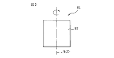
図2は粉末Pを容器内82で浮かせる手段84の変形例を示す図である。手段84は、粉末を入れた容器82を軸線84Dの回りで回転可能に支持し、容器82を機械的に回転させることにより、粉末を攪拌し、粉末を容器内で浮き上がらせるように構成される。なお、粉末を加熱する手段86は図2に示されていないが、図1を参照して説明したのと同様の手段を用いることができる。
When the powder is heated to a range of 700 ° C to 1500 ° C, the state of the surface of the powder changes. When heated to a range of 1000 ° C. to 1500 ° C., the surface of the powder changes more preferably. That is, the state of the surface of each fine particle constituting the powder changes, the surface energy of the powder becomes smaller, and the angle of repose becomes smaller. For this reason, when the powder is subsequently introduced into the aero deposition apparatus and the aero deposition apparatus is operated, the powder adheres securely to the substrate and a dense film structure can be obtained. As a result, a film structure having a high dielectric constant and low dielectric loss can be obtained. (A structure similar to the structure after grain growth of the sintered body can be obtained.)
FIG. 2 is a view showing a modification of the
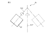
図3は粉末Pを容器内82で浮かせる手段84の変形例を示す図である。手段84は、粉末を入れた容器82を軸線84Eの回りで回転(自転)可能に支持し、かつ、回転する容器82を軸線84Eに対して角度をなす軸線84Fの回りで回転(公転)可能に支持し、容器82を機械的に回転させることにより、粉末を攪拌し、粉末を容器82内で浮き上がらせるように構成される。なお、粉末を加熱する手段86は図3に示されていないが、図1を参照して説明したのと同様の手段を用いることができる。
FIG. 3 is a view showing a modification of the
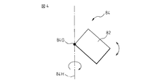
図4は粉末Pを容器内82で浮かせる手段84の変形例を示す図である。手段84は、粉末を入れた容器82を図4において紙面に垂直な軸線84Gの回りで上下に振動状に回転可能に支持し、かつ、容器82を軸線84Gに対して直交する軸線84Hの回りで回転(公転)可能に支持し、容器82を機械的に回転させることにより、粉末を攪拌し、粉末を容器82内で浮き上がらせるように構成される。なお、粉末を加熱する手段86は図4に示されていないが、図1を参照して説明したのと同様の手段を用いることができる。
FIG. 4 is a view showing a modification of the
図5は粉末Pを容器内82で浮かせる手段84の変形例を示す図である。手段84は、容器82内の粉末にガスを挿入する手段からなる。この手段は、下端部に小孔84Kを有する複数のノズル84Jからなる。ノズル84Jの小孔84Kから吹き出されたガスは容器82内の粉末を攪拌し、粉末を容器82内で浮き上がらせる。なお、粉末を加熱する手段86は図3に示されていないが、図1を参照して説明したのと同様の手段を用いることができる。
FIG. 5 is a view showing a modification of the
ノズル84Jに加えて図1のガス供給管88を設けることもできる。あるいは、ノズル84Jに図1のガス供給管88の機能をもたせることもできる。ガス供給管88およびノズル84Jは、窒素、酸素、アルゴン、および空気のうちのいずれかのガスを供給する。
In addition to the
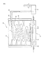
図6は本発明の他の実施例を示す図である。粉末調整装置80は、粉末Pを入れる容器82と、容器82に入っている粉末Pを容器内82で浮かせる手段84と、容器82に入っている粉末を加熱する手段86とを備える。さらに、粉末調整装置80は、搬送ガスを容器82に供給するガス供給管88と、粉末を搬送ガスとともに容器12から外部へ搬送する搬送管90とを備える。搬送管90は粉末を回収する回収容器92に接続され、回収容器92は真空吸引装置に接続される。
FIG. 6 is a diagram showing another embodiment of the present invention. The
粉末Pを容器内82で浮かせる手段84は、電気的に駆動されるファン84Mとして構成される。容器82内でファン84Mのすぐ上流側(粉末側)には、シャッタ94が配置される。また、搬送管90の容器82との接続部には、シャッタ96が配置される。さらに、容器82の内壁には螺旋状の突条98が形成されている。
The means 84 for floating the powder P in the
粉末を容器84に入れたら、ガス供給管88からガスを供給し、粉末を浮き上がらせる。そこで、ファン84Mを回し、粉末をさらに巻き上げる。粉末がある程度巻き上った状態で、シャッタ94,96を閉じる。ファン84Mを回しながら、粉末を加熱する手段86を作動させ、粉末を加熱する。このようにして、粉末を熱処理し、粉末の温度がある程度下がったところで、シャッタ96を開け、粉末を回収容器92に回収する。
When the powder is put in the
容器82の内壁には螺旋状の突条98が形成されているので、ファン84Mによって浮き上がった粉末は搬送ガスとともに矢印Sで示されるよう螺旋状のコースを通って進む。大きい微粒子は遠心力で容器82の内壁に付着し、小さい微粒子は搬送ガスとともに搬送管90に入り、回収容器92に回収される。回収容器92に回収された所定の粒径の粉末はエアロゾルデポジション装置へ送られることができ、あるいは容器82へ戻されて、容器82内の粉末が全体的に所定の粒径の粉末になるようにする。
Since the
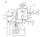
図7は本発明による粉末調整方法及び装置で処理された粉末を使用するエアロデポジション装置を示す図である。エアロゾルデポジション装置10は、ガスボンベ(ガス供給手段)12と、ガスボンベ12に接続され、粉末(微粒子)Pが入っていて微粒子Pがガスに分散したエアロゾルASを形成する容器14と、エアロゾルを基板36に向かって噴出するノズル16を有するチャンバ18と、チャンバ18を真空引きするための真空ポンプ(真空導入手段)20と、チャンバ18に残った微粒子を集塵するための集塵装置22とを備える。容器14は振動付与装置24に取付けられている。
FIG. 7 is a view showing an aero deposition apparatus using powder processed by the powder adjusting method and apparatus according to the present invention. The
微粒子Pは例えば粒径1μm以下の微小な粉末であり、例えばセラミック等の無機材料の微粒子(粉末)である。図1から図6を参照して説明した粉末調整装置80で処理された粉末が図7の容器12に入れられる。
The fine particles P are fine powders having a particle diameter of 1 μm or less, for example, fine particles (powder) of an inorganic material such as ceramic. The powder processed by the
管26がガスボンベ12と容器14とを接続し、マスフローメータ28およびバルブ30が管26に配置される。管26の一端部は容器14内に突出し、微粒子Pの内部に貫入している。管32が容器14とチャンバ18を接続し、バルブ34が管32に配置される。管32の一端部は容器14内に突出し、微粒子Pの上部に開口している。管32の他端部はチャンバ18内のノズル16に接続される。
A
ガスボンベ12は窒素や酸素等のガスを充填されており、マスフローメータ28によって制御された流量のガスが容器14に導入される。ガスは容器14内において微粒子P内に吹き出し、微粒子Pを舞い上がらせながら微粒子Pに混ざり、微粒子Pがガスに分散したエアロゾルASが形成される。形成されたエアロゾルは管32を介してチャンバ18内のノズル16に流れる。
The
基板36を保持する基板ホルダ38がチャンバ18内に配置されている。基板ホルダ38はXYステージ40に取付けられる。ノズル16は基板ホルダ38に保持された基板36と対向し、基板ホルダ38に保持された基板36はXYステージ40によって少なくともXY方向に移動される。
A
管42がチャンバ18と真空ポンプ20とを接続し、バルブ44及びメカニカルブースタ46が管42に配置される。バイパス管48が容器14と管42を接続し、バルブ50が管48に配置される。
A tube 42 connects the
さらに、管52がチャンバ18と集塵装置24を接続する。バルブ54が管52に配置される。集塵装置24は真空ポンプ56に接続される。さらに、清掃装置58がチャンバ18に設けられ、清掃装置58は管60を介して清掃用流体供給装置62に接続される。ヒータ64がチャンバ18に設けられる。
Further, a
以上の基本的な構成をもつエアロゾルデポジション装置10の作動について簡単に説明する。成膜プロセスに先立って、エアロゾルを形成する。バイパス管48のバルブ50を開き、バルブ30,34,44,54を閉じる。振動付与装置24を作動させて容器14を振動させながら、真空ポンプ20を作動させて容器14を排気し(真空を導入し)、微粒子Pに付着している水分を除去する。容器14にヒータが付属している場合には、ヒータも作動させる。また、このときに50℃以上のガスを流してもよい。それから、バルブ30を開き、ガスをガスボンベ12から容器14に導入する。ガスは微粒子Pの内部に吹き出し、舞い上がった微粒子Pがガスに分散しながらエアロゾルASを形成する。振動付与装置24及びヒータは適当な時期に停止する。
The operation of the
次に、成膜プロセスを行う。バルブ50,54を閉じ、バルブ30,34,44を開く。基板36をノズル16に対して対向配置させ、真空ポンプ20を作動させて容器14を真空に排気し、エアロゾルをノズル16から基板36に向かって噴出させる。エアロゾルは基板36に向かって進み、基板36に衝突して、エアロゾルに含まれる微粒子Pは基板36に付着、堆積する。従って、微粒子Pの材料の膜が基板36に形成される。
Next, a film forming process is performed. The
成膜プロセスが終了したら、バルブ30,34,44,50を閉じ、バルブ54を開く。清掃用流体供給装置62を作動させ、清掃装置58から清掃用流体を供給するとともに、ヒータ64を作動させる。それから、真空ポンプ56を作動させる。清掃用流体はチャンバ18の内部を清掃し、チャンバ18内に残留していた微粒子を集塵装置24に搬送する。
When the film forming process is completed, the
次に具体的な例について説明する。 Next, a specific example will be described.
例1
前処理として、平均粒径0.5μmのBaTiO3粉末を原料粉末として粉末調整装置80の容器82に入れ、容器82に全体的に超音波を加えた(超音波振動プロファイル、10kHz 1分、10kHz 30分、5kHz 1分、5Hz 30分、50kHz 5分、振動方向は水平、垂直、45度傾斜の3方向をランダムに)。約150℃で加熱しながら、30分真空脱気して、粉末表面に形成した水分を除去した。次に、容器内に、粉末上部に3本の羽根を挿入し、回転させた。(回転数プロファイル、50rpm 1分、100rpm 30分、10rpm 1分、50rpm 30分、30rpm 5分)。また、容器内にガス導入口を5本設け、粉末中に送気した。(各管への送気量は5l/分)。このガス気流体を全体から加熱して、粉末表面の熱処理を施した。
Example 1
As a pretreatment, BaTiO 3 powder having an average particle size of 0.5 μm was placed as a raw material powder in a
熱処理条件は、200℃、400℃、800℃、1000℃で実施した。また、1つの例では、ガスを送気しながら熱処理した粉体気流を遠心分離機(遠心分級機)に通し、その後、遠心分離機を通過したエアロゾルを回収した。 The heat treatment conditions were 200 ° C., 400 ° C., 800 ° C., and 1000 ° C. Moreover, in one example, the powder airflow heat-processed, sending gas, was passed through the centrifuge (centrifugal classifier), and the aerosol which passed the centrifuge was collect | recovered after that.
次に、前処理を施した原料粉末をエアロゾルデポジション装置の容器に入れ、高純度窒素ガス(ガス圧2kg/cm2、ガス流量4l/分)を導入し、原料をエアロゾルとした。このエアロゾルを管を通して、成膜用チャンバのノズルに供給した。ノズルは、内側に螺旋状の溝を形成したものを使用した。チャンバは予め真空に引き、圧力10Pa以下にする。エアロゾルをノズルからガラス基板に向けて10分間噴射を行った。このときのチャンバの中の圧力は200Paと一定であった。
Next, the pretreated raw material powder was put into a container of an aerosol deposition apparatus, and high purity nitrogen gas (
ガラス基板に形成されたBaTiO3の膜の厚さは60μmであった。また、膜の吸水率は0.01%以下であり、膜の基板間密着強度は5kg/mm2以上と強固であった。 The thickness of the BaTiO 3 film formed on the glass substrate was 60 μm. Further, the water absorption of the film was 0.01% or less, and the adhesion strength between the substrates of the film was as strong as 5 kg / mm 2 or more.
本方法を採用することにより、エアロゾル濃度のばらつきが小さく、安定したエアロゾルの形成が可能になった。得られた膜特性は表1に示す通りである。 By adopting this method, variation in aerosol concentration is small and stable aerosol formation is possible. The obtained film characteristics are as shown in Table 1.
例2
前処理として、平均粒径0.5μmのBaTiO3粉末を原料粉末として粉末調整装置80の容器82に入れ、容器14には3本の羽根を挿入し、回転させた。(回転数プロファイル、50rpm 1分、100rpm 30分、10rpm 1分、50rpm 30分、30rpm 5分)。また、容器内にガス導入口を5本設け、粉末中に送気した(各管への送気量は5l/分)。
Example 2
As a pretreatment, BaTiO 3 powder having an average particle size of 0.5 μm was placed as a raw material powder in a
この例では、容器82を1500℃で5時間加熱した。
In this example, the
次に、前処理を施した原料粉末をエアロゾルデポジション装置の容器に入れ、高純度窒素ガス(ガス圧2kg/cm2、ガス流量4l/分)を導入し、原料をエアロゾルASとした。このエアロゾルを管を通して、チャンバのノズルに供給した。ノズルは、内側に螺旋状の溝を形成したものを使用した。チャンバは予め真空に引き、圧力10Pa以下にする。エアロゾルをノズル16からガラス基板36に向けて10分間噴射を行った。このときのチャンバ18の中の圧力は200Paと一定であった。
Next, the pretreated raw material powder was put into a container of an aerosol deposition apparatus, high purity nitrogen gas (
ガラス基板に形成されたBaTiO3の膜の厚さは120μmであった。また、膜の吸水率は0.01%以下であり、膜の基板間密着強度は5kg/mm2以上と強固であった。 The thickness of the BaTiO 3 film formed on the glass substrate was 120 μm. Further, the water absorption of the film was 0.01% or less, and the adhesion strength between the substrates of the film was as strong as 5 kg / mm 2 or more.
本方法を採用することにより、エアロゾルの濃度のばらつきは5%と、安定した濃度のエアロゾルを形成することができた。成膜速度も再現性よく、12±1μm/分を得た。膜の誘電率は2000であった。 By adopting this method, it was possible to form an aerosol having a stable concentration of 5%, which is a variation in aerosol concentration. The film formation rate was also excellent in reproducibility, and 12 ± 1 μm / min was obtained. The dielectric constant of the film was 2000.
例3
前処理として、平均粒径0.5μmのBaTiO3粉末を原料粉末として粉末調整装置80の容器82に入れ、容器14内に150℃に加熱した窒素ガスを送気した(送気量は5l/分)。遠心分離機を通し、その後、遠心分離機を通過したエアロゾルを回収した。
Example 3
As a pretreatment, BaTiO 3 powder having an average particle size of 0.5 μm was placed as a raw material powder in a
次に、前処理を施した原料粉末をエアロゾルデポジション装置の容器に入れ、高純度窒素ガス(ガス圧2kg/cm2、ガス流量4l/分)を導入し、原料をエアロゾルとした。このエアロゾルを管を通して、チャンバのノズルに供給した。ノズルは、内側に螺旋状の溝を形成したものを使用した。チャンバは予め真空に引き、圧力10Pa以下にする。エアロゾルをノズルからガラス基板に向けて10分間噴射を行った。このときのチャンバ18の中の圧力は200Paと一定であった。
Next, the pretreated raw material powder was put into a container of an aerosol deposition apparatus, and high purity nitrogen gas (
ガラス基板に形成されたBaTiO3の膜の厚さは50μmであった。また、膜の吸水率は0.1%以下であり、膜の基板間密着強度は5kg/mm2以上と強固であった。 The thickness of the BaTiO 3 film formed on the glass substrate was 50 μm. Further, the water absorption of the film was 0.1% or less, and the adhesion strength between substrates of the film was as strong as 5 kg / mm 2 or more.
本方法を採用することにより、エアロゾル濃度のばらつきは2%と小さく、安定したエアロゾルの形成が可能になった。成膜速度も再現性よく、5±0.11μm/分を得た。膜の誘電率は1000であった。 By adopting this method, variation in aerosol concentration was as small as 2%, and stable aerosol formation was possible. The film formation rate was 5 ± 0.11 μm / min with good reproducibility. The dielectric constant of the film was 1000.
以上をまとめると、下記の表1に示される結果が得られた。 In summary, the results shown in Table 1 below were obtained.

以上説明したように、本発明によれば、エアロゾルの濃度にばらつきがなく、安定した濃度で、膜均質性を向上させ、再現性に優れた特性のエアロデポジション膜が得られ、高速成膜に効果的である。 As described above, according to the present invention, there is no dispersion in the aerosol concentration, an aerodeposition film having improved characteristics and excellent reproducibility can be obtained at a stable concentration, and high-speed film formation can be achieved. It is effective.
80…粉末調整装置
82…容器
84…粉末を浮かせる手段
86…粉末を加熱する手段
88…ガス供給管
90…搬送管
92…回収容器
94…シャッタ
96…シャッタ
98…螺旋状の突条
80 ...
Claims (5)
Priority Applications (1)
| Application Number | Priority Date | Filing Date | Title |
|---|---|---|---|
| JP2004105832A JP2005290460A (en) | 2004-03-31 | 2004-03-31 | Powder adjustment method and apparatus |
Applications Claiming Priority (1)
| Application Number | Priority Date | Filing Date | Title |
|---|---|---|---|
| JP2004105832A JP2005290460A (en) | 2004-03-31 | 2004-03-31 | Powder adjustment method and apparatus |
Related Child Applications (1)
| Application Number | Title | Priority Date | Filing Date |
|---|---|---|---|
| JP2009231830A Division JP5234289B2 (en) | 2009-10-05 | 2009-10-05 | Powder adjustment method and apparatus |
Publications (1)
| Publication Number | Publication Date |
|---|---|
| JP2005290460A true JP2005290460A (en) | 2005-10-20 |
Family
ID=35323727
Family Applications (1)
| Application Number | Title | Priority Date | Filing Date |
|---|---|---|---|
| JP2004105832A Pending JP2005290460A (en) | 2004-03-31 | 2004-03-31 | Powder adjustment method and apparatus |
Country Status (1)
| Country | Link |
|---|---|
| JP (1) | JP2005290460A (en) |
Cited By (1)
| Publication number | Priority date | Publication date | Assignee | Title |
|---|---|---|---|---|
| JP2009242844A (en) * | 2008-03-31 | 2009-10-22 | Fujitsu Ltd | Film deposition method |
Citations (5)
| Publication number | Priority date | Publication date | Assignee | Title |
|---|---|---|---|---|
| JPS61246576A (en) * | 1985-04-24 | 1986-11-01 | 株式会社大川原製作所 | Continuous fluidized-bed drier |
| JPH05302176A (en) * | 1991-08-09 | 1993-11-16 | Inter Metallics Kk | Method for forming coating film |
| JPH11302702A (en) * | 1998-04-22 | 1999-11-02 | Kubota Corp | Powder dryer |
| JP2003313227A (en) * | 2002-04-19 | 2003-11-06 | Sumitomo Chem Co Ltd | Degassing and drying of polymer powder |
| WO2003100131A1 (en) * | 2002-05-28 | 2003-12-04 | National Institute Of Advanced Industrial Science And Technology | Method for forming ultrafine particle brittle material at low temperature and ultrafine particle brittle material for use therein |
-
2004
- 2004-03-31 JP JP2004105832A patent/JP2005290460A/en active Pending
Patent Citations (5)
| Publication number | Priority date | Publication date | Assignee | Title |
|---|---|---|---|---|
| JPS61246576A (en) * | 1985-04-24 | 1986-11-01 | 株式会社大川原製作所 | Continuous fluidized-bed drier |
| JPH05302176A (en) * | 1991-08-09 | 1993-11-16 | Inter Metallics Kk | Method for forming coating film |
| JPH11302702A (en) * | 1998-04-22 | 1999-11-02 | Kubota Corp | Powder dryer |
| JP2003313227A (en) * | 2002-04-19 | 2003-11-06 | Sumitomo Chem Co Ltd | Degassing and drying of polymer powder |
| WO2003100131A1 (en) * | 2002-05-28 | 2003-12-04 | National Institute Of Advanced Industrial Science And Technology | Method for forming ultrafine particle brittle material at low temperature and ultrafine particle brittle material for use therein |
Cited By (1)
| Publication number | Priority date | Publication date | Assignee | Title |
|---|---|---|---|---|
| JP2009242844A (en) * | 2008-03-31 | 2009-10-22 | Fujitsu Ltd | Film deposition method |
Similar Documents
| Publication | Publication Date | Title |
|---|---|---|
| CN102428212B (en) | Method for forming zirconia film | |
| JP3809860B2 (en) | Composite structure manufacturing method and composite structure manufacturing apparatus | |
| JP2010133031A (en) | Film formation method and film formation apparatus | |
| JP5234289B2 (en) | Powder adjustment method and apparatus | |
| JP5909737B2 (en) | Yttria film deposition method | |
| CN101283118B (en) | Composite structure | |
| JP2005290460A (en) | Powder adjustment method and apparatus | |
| CN101171369A (en) | Manufacturing method of composite structure, impurity removal treatment equipment, film forming equipment, composite structure and raw material powder | |
| JP4371884B2 (en) | Aerosol deposition equipment | |
| JP4075716B2 (en) | Composite structure manufacturing equipment | |
| JP5649026B2 (en) | Method for forming zirconia film | |
| JP3825455B2 (en) | Aerosol generator, composite structure manufacturing apparatus, and composite structure manufacturing method | |
| JP5401960B2 (en) | Film forming method and film forming apparatus | |
| JP2009013472A (en) | Sputtering target, and manufacturing method and recycling method thereof | |
| JP2008214702A (en) | Film forming method and film forming apparatus | |
| JP3893513B2 (en) | COMPOSITE STRUCTURE, PROCESS FOR PRODUCING THE SAME, AND BRITICAL MATERIAL PARTICLE FOR FORMING COMPOSITE STRUCTURE | |
| JP4591498B2 (en) | Composite structure manufacturing method | |
| JP3372904B2 (en) | Film forming method and film forming apparatus | |
| JP2006219764A (en) | Aerosol generator, composite structure manufacturing apparatus, and composite structure manufacturing method | |
| JP4063187B2 (en) | Aerosol generator and composite structure manufacturing apparatus including the same | |
| JP4029347B2 (en) | Aerosol generator and composite structure manufacturing apparatus including the same | |
| JP5649028B2 (en) | Method for forming zirconia film | |
| JP2013019013A (en) | Aerosol generation apparatus and film deposition apparatus | |
| JP2010084223A (en) | Composite body of metal silicate film and glass base material, composite body of metal silicate film and the body to be film-formed, and method of producing the same | |
| JP2000256876A (en) | Gas deposition apparatus and method |
Legal Events
| Date | Code | Title | Description |
|---|---|---|---|
| A621 | Written request for application examination |
Free format text: JAPANESE INTERMEDIATE CODE: A621 Effective date: 20070216 |
|
| A977 | Report on retrieval |
Free format text: JAPANESE INTERMEDIATE CODE: A971007 Effective date: 20090107 |
|
| A131 | Notification of reasons for refusal |
Free format text: JAPANESE INTERMEDIATE CODE: A131 Effective date: 20090120 |
|
| A521 | Written amendment |
Free format text: JAPANESE INTERMEDIATE CODE: A523 Effective date: 20090319 |
|
| A131 | Notification of reasons for refusal |
Free format text: JAPANESE INTERMEDIATE CODE: A131 Effective date: 20090804 |
|
| A521 | Written amendment |
Free format text: JAPANESE INTERMEDIATE CODE: A523 Effective date: 20091005 |
|
| A02 | Decision of refusal |
Free format text: JAPANESE INTERMEDIATE CODE: A02 Effective date: 20100202 |