JP2005290088A - Fuel reforming method - Google Patents
Fuel reforming method Download PDFInfo
- Publication number
- JP2005290088A JP2005290088A JP2004104097A JP2004104097A JP2005290088A JP 2005290088 A JP2005290088 A JP 2005290088A JP 2004104097 A JP2004104097 A JP 2004104097A JP 2004104097 A JP2004104097 A JP 2004104097A JP 2005290088 A JP2005290088 A JP 2005290088A
- Authority
- JP
- Japan
- Prior art keywords
- fuel
- magnet
- fuel tank
- tank
- bottom wall
- Prior art date
- Legal status (The legal status is an assumption and is not a legal conclusion. Google has not performed a legal analysis and makes no representation as to the accuracy of the status listed.)
- Pending
Links
- 239000000446 fuel Substances 0.000 title claims abstract description 74
- 238000000034 method Methods 0.000 title claims abstract description 9
- 238000002407 reforming Methods 0.000 title claims description 7
- 239000002828 fuel tank Substances 0.000 claims abstract description 41
- 230000005291 magnetic effect Effects 0.000 claims abstract description 38
- 238000000429 assembly Methods 0.000 claims abstract description 14
- 230000000712 assembly Effects 0.000 claims abstract description 14
- 230000005294 ferromagnetic effect Effects 0.000 claims abstract description 10
- 239000003302 ferromagnetic material Substances 0.000 claims description 4
- 238000010030 laminating Methods 0.000 claims description 2
- 238000002485 combustion reaction Methods 0.000 abstract description 9
- 230000001846 repelling effect Effects 0.000 abstract description 5
- 239000004215 Carbon black (E152) Substances 0.000 abstract description 4
- 229930195733 hydrocarbon Natural products 0.000 abstract description 4
- 150000002430 hydrocarbons Chemical class 0.000 abstract description 4
- 229910000831 Steel Inorganic materials 0.000 description 9
- 239000010959 steel Substances 0.000 description 9
- 230000000694 effects Effects 0.000 description 5
- MWUXSHHQAYIFBG-UHFFFAOYSA-N nitrogen oxide Inorganic materials O=[N] MWUXSHHQAYIFBG-UHFFFAOYSA-N 0.000 description 5
- 230000004907 flux Effects 0.000 description 3
- 238000010586 diagram Methods 0.000 description 2
- 238000002474 experimental method Methods 0.000 description 2
- 229910001172 neodymium magnet Inorganic materials 0.000 description 2
- 239000002245 particle Substances 0.000 description 2
- UGFAIRIUMAVXCW-UHFFFAOYSA-N Carbon monoxide Chemical compound [O+]#[C-] UGFAIRIUMAVXCW-UHFFFAOYSA-N 0.000 description 1
- QVGXLLKOCUKJST-UHFFFAOYSA-N atomic oxygen Chemical compound [O] QVGXLLKOCUKJST-UHFFFAOYSA-N 0.000 description 1
- 229910002091 carbon monoxide Inorganic materials 0.000 description 1
- 238000006073 displacement reaction Methods 0.000 description 1
- 239000000295 fuel oil Substances 0.000 description 1
- 239000007789 gas Substances 0.000 description 1
- 239000003502 gasoline Substances 0.000 description 1
- 239000003921 oil Substances 0.000 description 1
- 239000001301 oxygen Substances 0.000 description 1
- 229910052760 oxygen Inorganic materials 0.000 description 1
- 239000000779 smoke Substances 0.000 description 1
- 229920003002 synthetic resin Polymers 0.000 description 1
- 239000000057 synthetic resin Substances 0.000 description 1
Images

Landscapes
- Production Of Liquid Hydrocarbon Mixture For Refining Petroleum (AREA)
Abstract
Description
本発明は燃料改質方法に関し、特に炭化水素系燃料の燃焼効率を大幅に改善できるようにした方法に関する。 The present invention relates to a fuel reforming method, and more particularly to a method capable of greatly improving the combustion efficiency of hydrocarbon fuel.
車両や船舶のエンジン等ではガソリン、軽油、重油等、各種の炭化水素系燃料が用いられる。この炭化水素系燃料は一般的に粒径50μm〜100μm程度の燃料分子が相互にファンデルワールス結合していると考えられ、このように燃料分子が結合した状態では酸素と接触効率が悪く、不完全燃焼を起こしやすいとされている。 Various hydrocarbon fuels such as gasoline, light oil, heavy oil, etc. are used in engines for vehicles and ships. This hydrocarbon fuel is generally considered to have van der Waals bonds with fuel molecules having a particle size of about 50 μm to 100 μm. In such a state where the fuel molecules are combined, the contact efficiency with oxygen is poor, It is said that complete combustion is likely to occur.
これに対し、燃料供給系において磁界中に燃料を通過させ、燃料分子の結合を切断して微粒化し、燃焼効率をアップさせる方法が提案されている(例えば、特許文献1、特許文献2、特許文献3、特許文献4、特許文献5、等参照)。 On the other hand, a method has been proposed in which fuel is passed through a magnetic field in a fuel supply system, the bonds of fuel molecules are cut and atomized, and combustion efficiency is increased (for example, Patent Document 1, Patent Document 2, Patent). Reference 3, Patent Document 4, Patent Document 5, etc.).
上述の磁気処理によって燃料分子を微粒化した燃料は燃料消費量を削減でき、窒素酸化物(NOX)や一酸化炭素の排出量を低減でき、さらにディーゼルエンジンの場合には排気ガス中の黒煙を少なくできることが報告されている。 Fuel that atomizes fuel molecules by the magnetic treatment described above can reduce fuel consumption, reduce emissions of nitrogen oxides (NOx) and carbon monoxide, and, in the case of diesel engines, black smoke in the exhaust gas. It has been reported that this can be reduced.
しかるに、燃料を磁気処理にて微粒化する場合、磁界中において燃料が2m/sec以上の速度で移動しないと磁気処理の効果が得られないが、燃料供給系において磁界中に燃料を通過させる方式では燃料の流通速度が遅く、十分に微粒化されず、燃費で数%の改善しか得られていないのが実情であった。 However, when the fuel is atomized by magnetic processing, the effect of the magnetic processing cannot be obtained unless the fuel moves at a speed of 2 m / sec or more in the magnetic field. However, the fuel is passed through the magnetic field in the fuel supply system. However, the actual situation was that the fuel flow rate was slow, the fuel was not sufficiently atomized, and only a few percent improvement in fuel consumption was obtained.
そこで、燃料タンク内に磁石を配設し、走行中における燃料タンク内での燃料の揺れを利用して磁界に対する燃料の移動を確保し、燃料を微粒化する方式が提案されている(例えば、特許文献6、特許文献7、特許文献8、等参照)。 In view of this, a method has been proposed in which a magnet is disposed in the fuel tank, the movement of the fuel in the fuel tank during traveling is ensured to ensure movement of the fuel relative to the magnetic field, and the fuel is atomized (for example, (See Patent Document 6, Patent Document 7, Patent Document 8, etc.).
しかし、上記従来のタンク内方式では磁界中を通過させる方式に比して燃焼効率が改善されているものの、燃費で10%未満の改善しか得られていないのが実情である。 However, although the conventional in-tank system has improved combustion efficiency as compared with a system in which it passes through a magnetic field, the actual situation is that only an improvement of less than 10% in fuel efficiency has been obtained.
本発明はかかる問題点に鑑み、燃焼効率を大幅にアップできるようにした燃料改質方法を提供することを課題とする。 In view of such problems, the present invention has an object to provide a fuel reforming method capable of greatly improving combustion efficiency.
そこで、本発明に係る燃料の改質方法は、相互に反発する磁界が燃料タンクの燃料送給口部近傍の壁面を貫通するように少なくとも2つの磁石体を相互に可能な限り接近させて燃料タンクの底面に設け、上記相互に反発する磁界を横切った燃料が燃料送給口部から送り出されるようになしたことを特徴とする。 Therefore, the fuel reforming method according to the present invention is configured so that at least two magnet bodies are as close as possible to each other so that magnetic fields repelling each other pass through the wall surface in the vicinity of the fuel supply port of the fuel tank. The fuel is provided on the bottom surface of the tank and crosses the magnetic fields repelling each other, and is sent out from the fuel delivery port.
磁界によって燃料を微粒化する場合、十分な大きさの磁界中を燃料が2m/sec以上の速度で移動する必要があることが本件発明者らの実験によって確認された。従来の燃料タンク内に磁石体を設ける方式ではタンク内燃料が速度2m/sec以上で移動して微粒化されても、その微粒燃料が燃料タンクからエンジンに向けて送給されるまでに燃料タンク内の未改質の燃料と混ざってしまい、燃焼効率を向上できなかったものと考えられる。 When the fuel is atomized by a magnetic field, it has been confirmed by experiments of the present inventors that the fuel needs to move in a sufficiently large magnetic field at a speed of 2 m / sec or more. In a conventional system in which a magnet body is provided in a fuel tank, even if the fuel in the tank moves at a speed of 2 m / sec or more and is atomized, the fuel tank does not pass until the fine fuel is delivered from the fuel tank to the engine. It is considered that the combustion efficiency could not be improved due to mixing with unreformed fuel.
これに対し、本発明の特徴の1つは相互に反発する磁界を相互に可能な限り接近させて燃料タンク外底面に磁着させて燃料タンク内に大きな磁界を形成し、その磁界を燃料送給口部近傍の燃料が横切るようにした点にある。 On the other hand, one of the features of the present invention is that magnetic fields repelling each other are made as close as possible to each other and magnetized to the bottom surface of the fuel tank to form a large magnetic field in the fuel tank. The fuel in the vicinity of the inlet is crossed.
これにより、燃料タンクの燃料送給口部近傍には少なくとも2つの磁界が形成されるが、これらの磁界は相互に反発するので、磁界が相互に反対側に大きく拡がる。その結果、燃料送給口部近傍の燃料が確実に磁界を所定速度以上で横切って微粒化され、そのまま燃料送給口部から送り出すことができるので、燃料タンク内に磁石体を設ける場合に比して同一の磁束密度の磁石体であっても燃料をより確実に微粒化することができ、燃焼効率を大幅にアップできる。 As a result, at least two magnetic fields are formed in the vicinity of the fuel supply port of the fuel tank, but these magnetic fields repel each other, so that the magnetic fields greatly expand on the opposite sides. As a result, the fuel in the vicinity of the fuel supply port is surely atomized across the magnetic field at a predetermined speed or more, and can be sent out from the fuel supply port as it is, so compared with the case where a magnet body is provided in the fuel tank. Thus, even with a magnet body having the same magnetic flux density, the fuel can be atomized more reliably, and the combustion efficiency can be greatly increased.
また、本発明に係る燃料改質器は、燃料タンクの底面に磁着される少なくとも2つの磁石組立体からなる燃料改質器であって、上記少なくとも2つの磁石組立体の各々は磁石体を上側、強磁性体を下側にして積層しかつ磁石体の同一の磁極面を上面にしてケースによって相互に固定した構造をなし、上記少なくとも2つの磁石組立体が相互に可能な限り接近した状態で磁石体が燃料タンクの底面に磁着されることを特徴とする。 The fuel reformer according to the present invention is a fuel reformer comprising at least two magnet assemblies magnetically attached to the bottom surface of the fuel tank, and each of the at least two magnet assemblies includes a magnet body. A structure in which the upper and lower layers are laminated with the ferromagnetic body on the lower side and the same magnetic pole surface of the magnet body is fixed to each other by a case, and the at least two magnet assemblies are as close as possible to each other The magnet body is magnetically attached to the bottom surface of the fuel tank.
磁石体の下側に強磁性体を設けたのは、強磁性体の作用によって磁力線が燃料タンクの底壁を貫通して燃料タンク内方まで延び、これによって燃料タンク内に大きな磁界を形成できるからである。 The reason why the ferromagnetic body is provided on the lower side of the magnet body is that the magnetic lines of force extend through the bottom wall of the fuel tank to the inside of the fuel tank due to the action of the ferromagnetic body, thereby forming a large magnetic field in the fuel tank. Because.
ここで、強磁性体の厚さは燃料タンクの底壁よりも厚くするのがよいことが本件発明者の実験によって確認された。また、強磁性体は磁石体とほぼ等しい厚さ又はそれ以上の厚さにするのがよいことも確認された。 Here, it was confirmed by experiments of the present inventors that the ferromagnetic material should be thicker than the bottom wall of the fuel tank. It was also confirmed that the ferromagnetic material should have a thickness approximately equal to or greater than that of the magnet body.
また、磁力線を燃料タンク内方まで貫通させる上で、強磁性体は複数の強磁性板を積層して構成するのがよい。 In order to penetrate the magnetic lines of force to the inside of the fuel tank, the ferromagnetic body is preferably formed by laminating a plurality of ferromagnetic plates.
この少なくとも2つの磁石組立体は最大の燃料改質効果を確保する上で、燃料タンクの燃料送給口部に対面する底壁外面に磁着されるのがよいが、他の部位の壁面外面に磁着しても従来の方式に比して優れた燃料改質効果が得られる。 In order to secure the maximum fuel reforming effect, the at least two magnet assemblies are preferably magnetically attached to the outer surface of the bottom wall facing the fuel supply port of the fuel tank. Even if magnetized, the fuel reforming effect superior to that of the conventional system can be obtained.
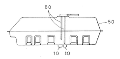
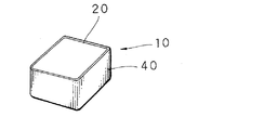
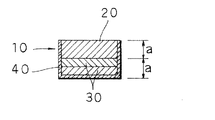
以下、本発明を図面に示す具体例に基づいて詳細に説明する。図1ないし図4は本発明に係る燃料改質器の好ましい実施形態を示す。図において、磁石組立体10は上面の開口した合成樹脂製のケース40内に、上側に磁石体20、下側に2枚の鉄鋼板(強磁性板)30を各々内蔵して構成されている。
Hereinafter, the present invention will be described in detail based on specific examples shown in the drawings. 1 to 4 show a preferred embodiment of a fuel reformer according to the present invention. In the figure, a
磁石体20には磁束密度400000μT(4000G)のネオジウム磁石が用いられ、N極が上面となるようにケース40内に設けられている。また、2枚の鉄鋼板30の厚さaは燃料タンク50の底壁の厚さ2.5mm〜3mmよりも大きく、又磁石体20の厚さaと2枚の鉄鋼板30の厚さaとはともに4.5mm〜5.0mmに設定されている。
The
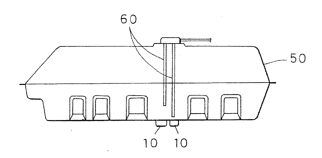
本例の磁石組立体10は2つを1組として用いる。本例の磁石組立体10を燃料タンク50に取付ける場合、燃料ポンプの吸込みホース60の先端開口(燃料送給口部)に対面する底壁外面に1組の磁石組立体10、10を相互に可能なかぎり接近させた状態で燃料タンク50の底壁外面に磁着させて取り付ける。
Two magnet assemblies 10 of this example are used as one set. When the
すると、燃料タンク50への磁着前においては磁石組立体10には図4の(a)に示すように、2枚の鉄鋼板30の作用によって上面N極より上方に磁力線が大きく形成される。
Then, before magnetic attachment to the
今、図4の(b)に示されるように、磁石体20の上下に同じ厚さの鉄鋼板80を磁着させた場合、磁力線は鉄鋼板80、80の間に形成され、鉄鋼板80を大きく貫通して形成されない。
As shown in FIG. 4B, when
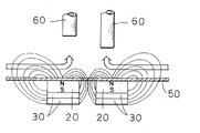
しかし、本例の磁石組立体10では2枚の鉄鋼板30の厚みが燃料タンク50の厚みに比して大きいので、磁石組立体10を燃料タンク50の底壁外面に磁着させると、図4の(c)に示されるように、磁力線は燃料タンク50の外壁を貫通して燃料タンク50の内方まで形成される。
However, since the thickness of the two
しかも、本例では2つの磁石組立体10、10を相互に可能なかぎり接近させているので、図5に示されるように、2つの磁石組立体10の磁力線は相互に反発し合い、相互に反対側に大きく拡がる。 In addition, in this example, the two magnet assemblies 10 and 10 are made as close as possible to each other, so that the magnetic lines of force of the two magnet assemblies 10 repel each other as shown in FIG. Expands greatly to the other side.
このような状態において、車両が走行すると、燃料タンク50内の燃料は吸込みホース60に吸い込まれてエンジンに供給されるが、燃料は走行に起因して揺れて磁界中を2m/sec以上の速度で大きく拡がった磁界中を横切って微粒化され、そのまま吸込みホース60に吸い込まれるので、燃焼効率が大幅に改善されることとなる。
In such a state, when the vehicle travels, the fuel in the
〔実施例1〕
1個の磁石体20に磁束密度400000μT(4000G)のネオジウム磁石を用いて磁石組立体10を製作した。2つの磁石組立体10を排気量4980ccのエンジンを搭載した乗用車の燃料タンクに取り付け、燃料消費量を調べ、磁石組立体を使用しない場合における燃料消費量と比較した。その結果を表1に示す。
[Example 1]
The
〔実施例2〕
実施例1と同じ磁石組立体10を用い、排気量3000ccのエンジンを搭載した乗用車の燃料タンクに取り付け、燃料消費量を調べた。その結果を表2に示す。
[Example 2]
The
〔実施例3〕
実施例1と同じ磁石組立体10を用い、排気量2500ccのディーゼルエンジンを搭載した乗用車の燃料タンクに取り付け、燃料消費量を調べた。その結果を表3に示す。
Example 3
The
〔実施例4〕
実施例1と同じ磁石組立体10を用い、排気量2000ccのエンジンを搭載した乗用車の燃料タンクに取り付け、燃料消費量を調べた。その結果を表4に示す。
Example 4
The
〔実施例5〕
実施例1と同じ磁石組立体10を用い、排気量600ccのエンジンを搭載した乗用車の燃料タンクに取り付け、燃料消費量を調べた。その結果を表5に示す。
Example 5
The
〔実施例6〕
実施例1と同じ磁石組立体10を用い、排気量2400ccのエンジンを搭載した乗用車の燃料タンクに取り付け、燃料消費量を調べた。その結果を表6に示す。
Example 6
The
10 磁石組立体
20 磁石体
30 鉄鋼板(強磁性体)
40 ケース
50 燃料タンク
60 燃料吸込みホース(燃料供給口部)
10
40
Claims (5)
上記少なくとも2つの磁石組立体の各々は磁石体を上側、強磁性体を下側にして積層しかつ磁石体の同一の磁極面を上面にしてケースによって相互に固定した構造をなし、
上記少なくとも2つの磁石組立体が相互に可能な限り接近した状態で磁石体が燃料タンクの底壁外面に磁着されることを特徴とする燃料改質器。 A fuel reformer comprising at least two magnet assemblies magnetized to the bottom surface of a fuel tank,
Each of the at least two magnet assemblies has a structure in which the magnet body is laminated on the upper side and the ferromagnetic body is on the lower side, and the same magnetic pole surface of the magnet body is placed on the upper surface and fixed to each other by a case.
A fuel reformer characterized in that the magnet body is magnetically attached to the outer surface of the bottom wall of the fuel tank with the at least two magnet assemblies as close as possible to each other.
The fuel reformer according to any one of claims 2 to 4, wherein the at least two magnet assemblies are magnetically attached to the outer surface of the bottom wall facing the fuel supply port of the fuel tank.
Priority Applications (1)
| Application Number | Priority Date | Filing Date | Title |
|---|---|---|---|
| JP2004104097A JP2005290088A (en) | 2004-03-31 | 2004-03-31 | Fuel reforming method |
Applications Claiming Priority (1)
| Application Number | Priority Date | Filing Date | Title |
|---|---|---|---|
| JP2004104097A JP2005290088A (en) | 2004-03-31 | 2004-03-31 | Fuel reforming method |
Publications (1)
| Publication Number | Publication Date |
|---|---|
| JP2005290088A true JP2005290088A (en) | 2005-10-20 |
Family
ID=35323397
Family Applications (1)
| Application Number | Title | Priority Date | Filing Date |
|---|---|---|---|
| JP2004104097A Pending JP2005290088A (en) | 2004-03-31 | 2004-03-31 | Fuel reforming method |
Country Status (1)
| Country | Link |
|---|---|
| JP (1) | JP2005290088A (en) |
-
2004
- 2004-03-31 JP JP2004104097A patent/JP2005290088A/en active Pending
Similar Documents
| Publication | Publication Date | Title |
|---|---|---|
| JPH10512640A (en) | High efficiency and environmentally friendly fuel economizer | |
| Kumar et al. | Experimental study of a novel magnetic fuel ionization method in four stroke diesel engines | |
| JP2015057555A (en) | Liquid fuel processing device | |
| WO2006022013A1 (en) | Magnetic processing equipment for engine and magnetic processing system for engine | |
| JP2005126042A (en) | Automotive fuel tank system | |
| US7527024B2 (en) | Liquid fuel reformer | |
| JP2007521434A (en) | Combustion gas preconditioning device | |
| JP2004143302A (en) | Method for modifying fuel | |
| JP2002122049A (en) | System for preventing air pollution by internal combustion engine, the internal combustion engine including air pollution preventing system, and fuel treating method and device thereof | |
| JP3380995B2 (en) | Exhaust gas toxic substance treatment equipment | |
| KR20170079501A (en) | Structure for Diesel Fuel Inlet with Inlet for Urea Solution | |
| CN201100205Y (en) | Fuel energy saving and emission reduction filter for internal combustion engine | |
| JP4287115B2 (en) | Feed fuel oil reformer | |
| JP3114781U (en) | Liquid fuel reforming magnetic processor for internal combustion engines | |
| KR100871420B1 (en) | Exhaust gas and fuel reduction device for internal combustion engine | |
| JP7072775B2 (en) | Fuel reformer for diesel engines | |
| US20170045020A1 (en) | System Containing Nanoparticles and Magnetizing Components Combined with an Ultrasonic Atomizer used for Saving Diesel in an Internal Combustion Engine | |
| JP2001164266A (en) | Fuel reformer | |
| JP3145261U (en) | Fuel reformer | |
| JP3030603U (en) | Fuel reformer | |
| JP2007127067A (en) | Combustion acceleration device for engine | |
| JP3094225U (en) | Diesel fuel condition improvement device | |
| EP3045710A1 (en) | A system containing nanoparticles and magnetizing components combined with an ultrasonic atomizer used for saving diesel in an internal combustion engine | |
| JP3214269U (en) | Fuel efficiency improvement device | |
| CN2620643Y (en) | Vehicule engine service life-increasing oil-saving device |