JP2005288570A - Working method and device for sheet-shaped workpiece - Google Patents
Working method and device for sheet-shaped workpiece Download PDFInfo
- Publication number
- JP2005288570A JP2005288570A JP2004103964A JP2004103964A JP2005288570A JP 2005288570 A JP2005288570 A JP 2005288570A JP 2004103964 A JP2004103964 A JP 2004103964A JP 2004103964 A JP2004103964 A JP 2004103964A JP 2005288570 A JP2005288570 A JP 2005288570A
- Authority
- JP
- Japan
- Prior art keywords
- work
- sheet
- roll
- workpiece
- pitch
- Prior art date
- Legal status (The legal status is an assumption and is not a legal conclusion. Google has not performed a legal analysis and makes no representation as to the accuracy of the status listed.)
- Pending
Links
Images


Abstract
Description
この発明は、連続的に走行変位される、プラスチック、紙、金属箔、複合紙等の、フィルム状部材をも含むシート状ワークに、印刷、型抜き、裁断、厚みの中間位置までのハーフカット等の加工を施すに用いて好適な、シート状ワークに対する作業方法および、その方法の実施に用いる作業装置に関するものであり、とくには、所定の同一の加工を、それの加工ピッチの長短にかかわらず、一種類の周長の作業ロールを用いて、高い作業効率の下で、高い精度で行なうことができる技術を提案するものである。 This invention is a sheet-like workpiece including a film-like member such as plastic, paper, metal foil, composite paper, etc., which is continuously displaced, and is half-cut to the middle position of printing, die cutting, cutting, and thickness. In particular, the present invention relates to a working method for a sheet-like workpiece and a working device used for carrying out the method, and in particular, a predetermined identical machining is performed regardless of the length of the machining pitch. Instead, the present invention proposes a technique that can be performed with high accuracy and high work efficiency by using a work roll having a single circumference.
たとえば、シート状ワークを、刷版を設けた作業ロールと支持ロールとの間に走行させて、所要の文字、図形、記号等の輪転印刷を行なう場合、または、裏面に粘着層を有するラベル用紙と、そのラベル用紙の裏面に予め貼着した剥離紙とからなる複合紙をシート状
ワークとし、周面上に、フレキシブルエッチング刃、彫刻刃その他からなる打抜刃を設けた作業ロールと支持ロールとの間にそのシート状ワークを通過させて、ワークのラベル用紙を、所要の輪郭形状等を有するラベル部分だけが剥離紙上に付着残留するように、ハーフカットをもって打ち抜く場合等において、シート状ワークを、作業ロールと支持ロールとの間に、それらの周速と等しい速度で連続的に走行させて、そのワークに印刷、打抜き等の所定ピッチの加工を施すときは、作業ロールの周長を、シート状ワークに施す加工ピッチ長さの一もしくは複数倍と対応する長さとすることが必要となる。
For example, when a sheet-like work is run between a work roll provided with a printing plate and a support roll to perform rotary printing of required characters, figures, symbols, etc., or label paper having an adhesive layer on the back surface And a work roll and a support roll provided with a punching blade comprising a flexible etching blade, a sculpture blade, etc. The sheet-like workpiece is punched with a half cut so that only the label portion having the required contour shape or the like remains on the release paper. Is continuously run at a speed equal to the peripheral speed between the work roll and the support roll, and the workpiece is subjected to processing at a predetermined pitch such as printing and punching. It is the circumferential length of the work roll, a primary or a multiple of processing pitch length applied to the sheet-like work and needs to be a corresponding length.
従って、連続走行するシート状ワークに、所要に応じて各種のピッチ長さの加工を施すためには、加工ピッチ長さに応じた周長を有する、各種寸法の作業ロール、着脱可能な刷版、打抜刃等を具える作業ロールにあっては各種寸法の作業ロール本体を予め多数本準備することが必要となって作業装置の設備コストが嵩むという問題があった。 Therefore, in order to process a sheet-like workpiece that runs continuously with various pitch lengths as required, work rolls with various dimensions according to the processing pitch length and removable printing plates. In a work roll having a punching blade or the like, it is necessary to prepare a large number of work roll bodies of various sizes in advance, resulting in an increase in equipment cost of the work apparatus.
そこで、一本の作業ロール本体を各種のピッチ長さの加工に対応させることによって設備コストの低減を図るべく、加工を施すシート状ワークを間欠的に走行させて、そのワークの走行の停止中に、作業手段を設けた作業ロールに、次の加工を準備させることが提案されており、現在広く一般に使用されている。 Therefore, in order to reduce the equipment cost by making one work roll body compatible with processing of various pitch lengths, the sheet workpiece to be processed is intermittently driven and the workpiece is stopped. In addition, it has been proposed that a work roll provided with working means be prepared for the next processing, and is now widely used.
しかるに、シート状ワークを間欠的に送拾して、そのワークの走行中に作業ロールをもって、たとえば一ピッチ分の印刷、打抜き等の加工をその全体にわたって適正に行なうためには、シート状ワークの一回の送り込み量を一ピッチ分の加工長さより相当長くすることが必要になり、この一方で、そのワークに対する次の一ピッチ分の加工を、ワークの無駄なく、所期した通りの位置から開始するためには、余分に送り込んだワーク部分を、作業ロールの次の加工の準備中もしくはその前後に引き戻し変位させることが必要となるので、その引き戻し変位工程の存在が、シート状ワークの送り込み駆動部等の機構および作動制御を複雑にする他、ワークの繰返しの往復変位が、ワークの位置決め精度の低下を余儀なくして、高い加工精度の確保を難しくするという問題があった。 However, in order to carry out processing such as printing, punching, etc. for one pitch properly over the whole by feeding and picking up a sheet-like work intermittently and using a work roll while the work is running, It is necessary to make the amount of one feed considerably longer than the machining length for one pitch. On the other hand, machining for the next one pitch for the workpiece can be performed from the expected position without wasting the workpiece. In order to start, it is necessary to pull back the workpiece part that has been sent in excess during preparation for the next processing of the work roll or before and after that, so the presence of the pull back displacement process In addition to complicating the mechanism and operation control of the drive unit, repeated reciprocating displacement of the workpiece necessitates a decrease in workpiece positioning accuracy, ensuring high machining accuracy. There is a problem that the makes it difficult.
そこで、出願人は先に、これらの問題点を解決することを目的として、間欠送り走行させたシート状ワークの引き戻し工程を不要とする技術を特開2003−305694号として提案し、また、シート状ワークの余剰の送り込みに起因するそれの引き戻し工程において、引き戻されるワークの弛み等を、極く狭いワークの延在範囲内で十分に吸収することで、ワークの送り込みおよび引張り駆動部等の機構および作動制御の複雑化を防止するとともに、高い作業精度を確保する技術を特願2003−349362号として提案した。
しかるに、これらの提案技術はいずれも、シート状ワークを間欠的に送り走行させることを前提とするものであることから、作業能率の低さが否めず、また、ワークの走行および停止を繰り返すこと等に起因する加工精度の低さが否めないという問題があった。 However, since all of these proposed technologies are based on the premise that the sheet-like workpiece is intermittently fed and traveled, the work efficiency cannot be denied, and the workpiece is repeatedly run and stopped. There is a problem that the low processing accuracy due to the above cannot be denied.
この発明は、これらの点に着目してなされたものであり、それの目的とするところは、すぐれた作業能率と併せて、高い加工精度を実現することができる、シート状ワークに対する作業方法および、その方法の実施に用いる作業装置を提供するにある。 The present invention has been made paying attention to these points, and an object of the present invention is to provide a working method for a sheet-like workpiece capable of realizing high machining accuracy in combination with excellent work efficiency and The present invention provides a working device used for carrying out the method.
この発明に係る、シート状ワークに対する作業方法は、シート状ワークを、相互に協働して作業を行なう支持ロールと、周面に作業手段を設けた、作業手段より大周長の作業ロールとを具える複数段の作業ステーションに通過させて、そのシート状ワークに、通常は、時間差をおいた異なるタイミングで間欠的に作動して、支持ロールと同一周速で回動変位するそれぞれの作業ロールによって、所定の同一の加工を一定ピッチで施す方法であって、それぞれの作業ステーションの各作業ロールで、連続走行するシート状ワークに、前記ピッチの整数倍の間隔をおいて加工を施すとともに、複数のそれぞれの作業ロールによって、シート状ワークの未加工部分の全てに一定ピッチの加工を施すにある。 A working method for a sheet-like workpiece according to the present invention includes: a support roll for working the sheet-like workpiece in cooperation with each other; and a work roll having a longer circumference than the working means provided with working means on the peripheral surface. Each work that is moved intermittently at different timings with a time difference and rotated and displaced at the same peripheral speed as the support roll is usually passed through the multi-stage work station. This is a method of performing predetermined identical processing at a constant pitch by a roll, and processing is performed at intervals of an integral multiple of the pitch on a continuously traveling sheet-like workpiece with each work roll of each work station. A plurality of respective work rolls are used to process a fixed pitch on all unprocessed portions of the sheet-like workpiece.
なおここで「同一の加工」とは、たとえば、印刷、型抜き、ハーフカット等の各種の加工のうちの同一種類の加工をいうものとし、この同一種類の加工は、輪郭形状、寸法、色彩等が全く同一の場合のみならず、それらの少なくとも一つが相互に相達する場合をも含むものとする。
従って、ハーフカットに例をとると、たとえば、犬、猫、猿等の各種の動物その他の輪郭形状等を所要の順序に従って抜き加工する場合もここでいう同一の加工に含まれることになる。
Here, the “same processing” refers to the same type of processing among various types of processing such as printing, die cutting, and half-cut, and the same type of processing includes the contour shape, dimensions, color, and so on. Etc. are not only the same, but also includes the case where at least one of them is mutually compatible.
Therefore, taking an example of half-cutting, for example, a case where various kinds of animals such as dogs, cats, monkeys, and other contour shapes are cut out according to a required order is included in the same processing here.
ここで好ましくは、シート状ワークを、一本の共通の支持ロールに巻き掛けて、その支持ロールの円周方向に間隔をおく複数段の作業ステーションに順次通過させる。 Preferably, the sheet-like work is wound around a common support roll and sequentially passed through a plurality of work stations spaced in the circumferential direction of the support roll.
ところでこの場合、複数段の作業ステーションのそれぞれの作業ロールは、支持ロールとともに、連続的に回転するものとすることも可能であるが、このときは、従来技術で述べたように、作業ロール本体の周長を、ワークに施す加工ピッチの複数倍に相当する長さに揃えることが必要になり、その加工ピッチの変更に伴って、作業ロール本体の周長を変えることが必要になるので、好ましくは、前段側の作業ステーションと後段側の作業ステーションとの相互間で、連続走行するシート状ワークに対し、前段側の作業ロールによる加工の終了後に、後段側の作業ロールが加工作動を開始するように、作業ロールを、異なったタイミングで間欠的に回転作動させる。すなわち、後段側の作業ロールの作動を、前段側の作業ロールによる加工が終了するまで待機させることが好ましい。 By the way, in this case, each work roll of the multi-stage work station can be continuously rotated together with the support roll. In this case, as described in the prior art, the work roll main body It is necessary to align the circumference of the work roll to a length corresponding to multiple times the machining pitch applied to the workpiece, and it is necessary to change the circumference of the work roll body with the change of the machining pitch, Preferably, for the sheet-like workpiece that continuously travels between the work station on the front stage side and the work station on the rear stage side, the work roll on the rear stage side starts the machining operation after finishing the work with the work roll on the front stage side. Thus, the work roll is intermittently rotated at different timings. That is, it is preferable to wait for the operation of the work roll on the rear stage until the processing by the work roll on the front stage is completed.
また、この発明に係る、シート状ワークに対する作業装置は、一本の共通の支持ロールの周りで、それの円周方向に間隔をおいて、支持ロールと協働する複数本の作業ロールのそれぞれを、たとえば、支持ロール、ひいては、その周面に対して進退変位可能に配設して複数段の作業ステーションを構成し、各作業ロール本体の周長を、そこに設けた作業手段の周方向長さより長い適宜の長さとするとともに、相互に隣接するそれぞれの作業ロールの周面に、ともに同一の作業手段を設けたものである。
ここで「同一の作業手段」とは、先に述べた「同一の加工」を施すための作業手段をいうものとする。
Further, the working device for the sheet-like workpiece according to the present invention includes a plurality of work rolls cooperating with the support rolls around a common support roll at intervals in the circumferential direction thereof. For example, a support roll, and thus a plurality of work stations that are arranged so as to be movable back and forth with respect to the peripheral surface thereof, and the circumferential length of each work roll main body is set in the circumferential direction of the work means provided there The length is set to an appropriate length longer than the length, and the same working means is provided on the peripheral surfaces of the respective work rolls adjacent to each other.
Here, the “same working means” refers to working means for performing the “same processing” described above.
かかる装置において、それぞれの作業ロール本体の周長は、作業手段の配設個所数、作業ロール本数等との関連において、相互に異なるものとすることも可能であるが、それらの周長はともに同一とすることが好ましい。 In such an apparatus, the circumference of each work roll body can be different from each other in relation to the number of work means disposed, the number of work rolls, etc. Preferably they are the same.
またそれぞれの作業ロールの周面には、相互に異なった個数の作業手段を配設することも可能であるが、好ましくはともに同数の作業手段を配設する。 Further, it is possible to dispose different numbers of working means on the peripheral surface of each work roll, but preferably the same number of working means are provided together.
この発明の作業方法によれば、支持ロールの周速と等しい速度で連続走行するシート状ワークに対し、たとえば、相互に独立して間欠的に回動作動される複数の作業ロールの各々で、一ピッチおきにまたは複数ピッチおきに、ともに所定の同一の加工を施し、そして、そのワークが、全ての作業ロールを通過した時点で、シート状ワークの全体に、所期した通りの加工部分間隔を含む一定ピッチの加工を施すことで、ワークを間欠的に送り走行させることが不要となるので、一本の作業ロールだけで、一定ピッチの加工の全てを行なう上記従来技術に比して、同一の加工を施す作業ロールの本数の、作業ステーションの数に応じた増加は不可避となるも、作業能率を大きく向上させることができ、また、ワークの走行および停止を繰り返すことおよび、それに引き戻し工程を付加すること等に起因する加工精度の低下のおそれを十分に取り除くことができる。 According to the work method of the present invention, for a sheet-like workpiece that continuously runs at a speed equal to the peripheral speed of the support roll, for example, each of a plurality of work rolls that are intermittently rotated independently of each other, When the same predetermined machining is performed at every other pitch or every other pitch, and when the workpiece has passed all the work rolls, the entire portion of the sheet-like workpiece is subjected to the machining interval as expected. Since it is not necessary to feed and run the workpiece intermittently by performing processing at a constant pitch including, compared to the above-described conventional technology that performs all processing at a constant pitch with only one work roll, Although it is inevitable that the number of work rolls that perform the same processing will increase according to the number of work stations, the work efficiency can be greatly improved, and the work can be repeatedly run and stopped. And, it is possible to remove a fear of decrease in working accuracy due to such the addition of step pullback it sufficiently.
なおここで、シート状ワークを巻き掛けた、一本の共通の支持ロールの周りに配設した複数段のそれぞれの作業ステーションに、そのワークを順次に通過させてそれに所定の加工を施す場合は、ワークを複数本の支持ロールを経て走行させる場合に比し、ワークに作用する張力の変動等を取り除くことができ、加工精度を一層高めることができる。 Here, when a predetermined work is performed by sequentially passing the work to each of the work stations in a plurality of stages arranged around one common support roll around which the sheet-like work is wound. Compared with the case where the workpiece is caused to travel through a plurality of support rolls, fluctuations in the tension acting on the workpiece can be removed, and the processing accuracy can be further improved.
またここにおいて、前段側の作業ステーションと後段側の作業ステーションとの相互間で、前段側の作業ロールによる加工の終了の後に、後段側の作業ロールの間欠的な回動運動に基いてそれの加工作動を開始させる場合は、作業ロールの、作業手段を除いた本体の周長を、各種の作業手段の周方向長さより長い適宜の周長に選択して、各作業ロールに、所定の加工を開始するに至るまでの待ち時間を付与するとともに、それぞれの作業ロールの加工開始タイミングを相互にずらすことで、一種類の周長の作業ロール本体を、ワークに対する各種の加工ピッチに常に適正に対応させることができ、周長の異なる複数種類の作業ロール本体の予めの準備を不要とすることができる。 Also, here, after the processing by the work roll on the front stage is completed between the work station on the front stage and the work station on the rear stage, it is based on the intermittent rotational movement of the work roll on the rear stage. When starting the machining operation, select the perimeter of the main body of the work roll excluding the work means to an appropriate circumference longer than the circumferential lengths of the various work means, In addition to giving a waiting time until the start of the work, and by shifting the processing start timing of each work roll relative to each other, the work roll body of one type of circumference is always suitable for various processing pitches for the workpiece Therefore, it is possible to eliminate the need for preparing in advance a plurality of types of work roll bodies having different circumferences.
この発明の作業装置では、一本の共通の支持ロールの周りに、複数段の作業ステーションを構成することにより、作業ステーション毎に各一本の支持ロールを配設する場合に比して、装置の構造を簡単にするとともに、装置の全体を小型化することができ、装置コストを有効に低減させることができる。 In the working device of the present invention, by forming a plurality of work stations around one common support roll, compared to the case where one support roll is provided for each work station, the device In addition to simplifying the structure, the entire apparatus can be reduced in size, and the apparatus cost can be effectively reduced.
そしてこの装置では、シート状ワークを連続走行させて、それを複数段の作業ステーションに順次に通過させるに当って、たとえば、それぞれの作業ステーションの作業ロールをともに、相互の独立下で、間欠的に回動させるとともに、シート状ワークに対するそれぞれの作業ロールの作動のタイミングを相違させて、前後の作業段の作業ロールの、ともに同一の作業手段の相互をシート状ワークに対して、待ち時間を挟んで交互に機能させて、シート状ワークの所定位置に、前段側の作業ロールによって加工を施した後、後段側の作業ロールにより、前段側作業ロールによる加工が行なわれていないワーク部分に所定の加工を施し、これらのことを全ての作業段にわたって繰り返すことで、作業段数の多少にかかわらず、前記作業方法を、円滑にかつ確実に実施することができる。 In this apparatus, when a sheet-like workpiece is continuously run and sequentially passed through a plurality of stages of work stations, for example, the work rolls of the respective work stations are intermittently separated from each other. The operation timing of each work roll with respect to the sheet-like workpiece is made different, so that the waiting time for the sheet-like workpiece between the work rollers of the front and rear work stages is mutually reduced. After the sheet-like workpiece is processed by a front work roll at a predetermined position of the sheet-like workpiece, the work portion not processed by the front work roll is predetermined by the rear work roll. The above-mentioned working method is performed regardless of the number of work stages, by repeating these operations over all work stages. It can be and reliably carried out smooth.
ここで、それぞれの作業ロール本体の周長をともに同一としたときは、装置の構造、作業ロールの作動制御等をより簡単なものとするとともに、各作業ロールに一個、もしくはそれ以上の作業手段を配設することで、ワークに対する一定ピッチ毎の所定の加工をより簡単に行なうことができる。 Here, when the circumference of each work roll body is the same, the structure of the apparatus, the operation control of the work roll, etc. are simplified, and one or more work means are provided for each work roll. By arranging the above, it is possible to more easily perform a predetermined machining for each workpiece at a certain pitch.
またここで、それぞれの作業ロールの周面に、ともに同数の作業手段を配設した場合には、作業手段の配設数をランダムにする場合に比して、所定の加工を一層容易にかつ効率良く行なうことができ、これらのことは、作業手段の配設数を複数個の同一数とした場合により効果的である。 Also, here, when the same number of working means are arranged on the peripheral surfaces of the respective work rolls, the predetermined processing can be performed more easily and more easily than when the number of working means is random. This can be done efficiently, and these are more effective when the number of working means is the same.
なお、シート状ワークへの加工の施し方の態様のいかんによっては、特定の作業ロールについては、作業手段の配設数を不同とすることが必要となる場合もあることはもちろんである。 Of course, depending on the manner of processing the sheet-like workpiece, it may be necessary for the specific work rolls to have the same number of working means.
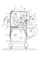
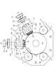
図1は、この発明に係る作業装置の適用形態を示す略線正面図であり、図2は、その作業装置の実施形態を、手前側の支持フレームを取り外して示す拡大図である。
図1に示すところにおいて、1は作業装置の駆動系その他を収納するハウジングを示し、2、3および4はそれぞれ、ハウジング1に突設した、たとえばブレーキ付きの繰出軸を示す。
FIG. 1 is a schematic front view showing an application mode of a working device according to the present invention, and FIG. 2 is an enlarged view showing an embodiment of the working device with a support frame on the near side removed.
In FIG. 1,
ここで、これらの繰出軸2、3、4のそれぞれは、たとえば、裏面に粘着層を有するラベル用紙と、このラベル用紙の裏面に貼着させた剥離紙との積層構造になる原反5、保護紙6およびカバーフィルム7のそれぞれの繰出軸として機能させることができる。
Here, each of these
また図中8は、ハウジング1の外側へ迫出し配置した巻取軸を示し、図示のこの巻取軸8は、ブラケット9を介して、ハウジング1に突設した巻取軸10の基部に連結されて、たとえば、打ち抜き加工後に剥離紙から分離等された不要部分を巻き取るべく回転駆動させることができる。
そして11は、打ち抜き等の所要の加工を施された製品シートを、スリッター装置を経て、または経ることなく巻き取り巻回することができる巻取軸を示す。
Reference numeral 11 denotes a take-up shaft that can take up and wind a product sheet that has undergone required processing such as punching through or without going through a slitter device.
ここで、この発明に係る作業装置は、手前側の支持フレーム13を取り除いて図2に拡大して示すように、後方側の支持フレーム14の中央部に大径の剛性支持ロール15を突設形成するとともに、この支持ロール15の周りで、その円周方向に間隔をおいて、図では45°の間隔をおいた二個所に、支持ロール周面に対して進退可能にそれぞれの作業ロール16、17、たとえば、フレキシブルエッチング刃からなる、作業手段としての、ともに同一の前記ハーフカット加工を施すそれぞれの打抜刃18、19を磁気吸着させてなる作業ロール16、17を配設して、一本の共通の支持ロール15の円周上に、相互に間隔をおく二個所の作業ステーションS1、S2を構成してなり、これらのそれぞれの作業ステーションS1、S2で、支持ロール15と作業ロール16、17との間を連続的に走行する一枚のシート状ワークWの相互に異なる位置に、互いに異なるタイミングで間欠的に回動作動されるそれぞれの作業ロール16、17の作用下で、形状および寸法等が全く同一のまたは、それらの少なくとも一つが相互に異なる打抜き加工を、予め定めた一定のピッチで順次に施す。
Here, the working device according to the present invention is provided with a large-diameter
これがために、ここでは各作業ロール16、17から打抜刃18、19を取外した各作業ロール本体20、21の周長を、各種寸法の打抜刃の円周方向長さよりも十分大きい長さとし、好ましくは、両ロール本体20、21の周長をともに同一とする。
For this reason, the circumferential length of each
なおここでは、作業手段を打抜刃18、19としているも、それを、印刷用の刷版その他とすることも可能であり、また、作業ステーションの数は、二個を最小単位として適宜増加させることも可能である。
Here, although the working means is the
ところで、図に示すところにおいて、それぞれの作業ロール本体20、21に、各一枚づつの打抜刃18、19を設けた場合において、支持ロール15を図2の矢印方向に回転駆動させ、ワークWを矢印A方向へその周速と等しい速度で連続走行させて、はじめに、作業ステーションS1の作業ロール16で、そのシート状ワークWに、一定ピッチの二倍のピッチで打抜き加工を施して、ワークWに対する加工部分間に、一ピッチ相当分の未加工部分を残留させ、次いで、作業ステーションS2の作業ロール17で、上記の残留未加工部分に打抜き抜きを施すときは、たとえば、間欠的な回動運動によって、シート状ワークWに対して一回の加工を施した後の作業ロール16を、ワークWのその後の一ピッチ分の長さが作業ロール16を通過するまでは、次回の加工開始位置に停止させて待機させ、また、後段側の作業ロール17は、前段側の作業ロール16によって加工を施された一ピッチ分のワーク部分がそのロール17を通過するまでは、それの作動を待機させ、この一方で、作業ロール16によって加工が行われなかったピッチ部分が作業ロール17に到達したときに、その作業ロール17を間欠的に作動させて、ワークWの、一ピッチ相当分の残留未加工部分に加工を行わせ、これらのことをシート状ワークWの全長にわたって繰り返すことで、全ての加工を終えた製品シートには、所定の一定ピッチ毎の同一の打抜き加工、たとえば、全てが同一の輪郭形状を有する、または、輪郭形状が一ピッチ毎に交互に変化する等の打ち抜き加工が施されることになる。
By the way, as shown in the figure, when the work roll
このようにここでは、作業ステーションS1での、ワークWに対する一の打抜き加工の終了後は、ワークWの、その後に続く一ピッチ分を、作業ステーションS1での加工を行なうことなくそこを通過させることで、打抜刃18の後端によるワークWの損傷のおそれを十分に取り除くことができ、この一方で、作業ステーションS2では、シート状ワークWの残留未加工部分に対して作業ステーションS1での加工と同一の加工を施し、ワークWの既加工部分は、ステーションS2での加工を行なうことなく通過させることで、ワークWの走行の停止、それの引き戻し変位等の必要なしに、シート状ワークWに、すぐれた作業能率をもって、一定ピッチ毎の所定の同一の加工を、その全長にわたって所期した通りに正確に行なうことができる。
As described above, after one punching process for the workpiece W at the work station S1 is completed, the subsequent pitch of the workpiece W is passed therethrough without being worked at the work station S1. Thus, the possibility of damage to the workpiece W due to the rear end of the
ここで、好ましくは、それぞれの作業ロール本体20、21の周長を、図示のようにともに同一とし、また、それぞれの作業ロール16、17の周面にはともに同数の打抜刃を設けることが好ましい。
Here, preferably, the circumferential lengths of the respective
なお、作業ロール本体の周長を十分長くして、それぞれの周面上に、二枚以上の、好ましくは相互に周数の打抜刃を、所定の加工ピッチの整数倍の間隔をおいて配設したときは、各作業ロールの一回の間欠作動は、周面上の打抜刃の全てが一回の仕事を終えた後に停止されることになる。 It should be noted that the work roll main body has a sufficiently long peripheral length, and two or more, preferably mutual punching blades, are spaced apart by an integral multiple of a predetermined processing pitch on each peripheral surface. When arranged, one intermittent operation of each work roll is stopped after all the punching blades on the peripheral surface have finished one work.
これをたとえば、周長が十分長い三本の作業ロール本体を一組として、それらのそれぞれ周面に、二ピッチ相当分の間隔をおいて三枚づつの打抜刃を配設して、第1ピッチから第9ピッチまでのそれぞれのピッチ加工を施す場合にあって、最初の作業ステーションで第1、第4および第7ピッチの、中段の作業ステーションで第2、第5および第8ピッチの、そして終段の作業ステーションで第3、第6および第9ピッチのそれぞれの加工を施す場合についてみると、それぞれの作業ロールは、相互に異なるタイミングで間欠的に作動されて、周面上の全ての打抜刃が一回の仕事を終えた後、シート状ワークWの二ピッチに相当する長さが通過するまでの間、次の作動を待機して停止されることになる。 For example, a set of three work roll bodies having a sufficiently long circumference is provided as a set, and three punching blades are arranged on each of the circumferential surfaces with an interval corresponding to two pitches. When each pitch machining from 1 pitch to 9th pitch is performed, the first, fourth, and seventh pitches are performed at the first work station, and the second, fifth, and eighth pitches are performed at the middle work station. In the case where the third, sixth, and ninth pitches are processed at the final stage work station, the respective work rolls are intermittently operated at different timings and After all the punching blades have completed one work, they are stopped after waiting for the next operation until a length corresponding to two pitches of the sheet-like workpiece W passes.
ところで、図面に示すそれぞれの作業ロール16、17は、それらの両端部に嵌合させたそれぞれの軸受ブロック22、23を、図2の拡大正面図および、図3の斜視図に示すように、前後の両支持フレーム13、14に形成されて、支持ロール15の半径方向に延びるそれぞれの切欠き24、25内へ、その半径方向に摺動変位可能に嵌め込むとともに、それらのそれぞれの軸受ブロック22、23を、切欠き24、25の底部に着座させたそれぞれのスプリング26、27によって半径方向外方へ付勢する一方で、切欠き24、25の開口を塞ぐように支持フレーム13、14に固定した架橋部材28、29に螺合する雄ねじ部材30、31で、半径方向内方へ押込むことによって支持フレーム13、14に取付けることができる。
By the way, as shown in the enlarged front view of FIG. 2 and the perspective view of FIG. The front and rear support frames 13 and 14 are fitted into the
このような作業ロール16、17は、雄ねじ部材30、31の締め込み操作により、中心軸線を支持ロール15のそれとほぼ平行に維持しつつ、打抜刃18、19が支持ロール周面から所定の距離に至るまでその周面に近接させることができ、逆に雄ねじ部材30、31を緩めることで、スプリング26、27の作用下で、支持ロール周面から離隔変位させることができる。
Such work rolls 16, 17 maintain the center axis substantially parallel to that of the
なお図中32、33は、それぞれの雄ねじ部材30、31に螺合させたそれぞれのロックナットを示す。
また、図2中、34、35および36はそれぞれ、シート状ワークWを支持ロール15の周面に弾性的に押圧するニップロールを示し、このようなニップロールは、シート状ワークWの適正なる走行をもたらすべく適宜に増減することができる。
In the figure,
In FIG. 2, 34, 35, and 36 indicate nip rolls that elastically press the sheet-like work W against the peripheral surface of the
図面に示すこのような装置を用いた、この発明に係る作業方法の実施に当っては、たとえば図2に示すように、シート状ワークWを一本の大径の剛性支持ロール15の周りに巻き掛けるとともに、それを支持ロール15の周面に、それぞれのニップロール34、35、36によって弾性的に押圧し、また、支持ロール15の円周方向に間隔をおくそれぞれの作業ステーションS1、S2で、それぞれの作業ロール16、17の各一枚の打抜刃18、19が、ワークW内へ所定の深さに食い込む位置まで、両ロール16、17を支持ロール15の周面に近接変位させた状態で、支持ロール15を図の矢印方向に連続的に回転させ、これによって連続走行されるシート状ワークWに対し、はじめに作業ステーションS1の作業ロール16を間欠的に回動させてシート状ワークに、図4(a)に例示するように、所定の加工ピッチPの二ピッチに一回の打抜き加工L1、いいかえれば、一ピッチ分の間隔をおいた打抜き加工L1を施す。
この場合、作業ロール16は、1回の加工を終えた後、ワークWが一ピッチ分に相当する長さ分だけをその作業ロール16を通過するまでの間作動を停止されて、次の作動を待機する。
In carrying out the working method according to the present invention using such an apparatus shown in the drawings, for example, as shown in FIG. 2, a sheet-like workpiece W is placed around one large-diameter
In this case, the operation of the
その後は、作業ステーションS2の作業ロール17で、そのワークWの、残りの未加工部分の全てに、これも一ピッチ分の間隔をおいた打抜き加工L2を施す。
作業ロール17のこの作動は、前段の作業ロール16によって加工を施されたワーク部分がそのロール17を通過した後に間欠的に行われることになり、1回の加工を終えた作業ロール17は、その後再び作動を停止されて、前段のロール16による一ピッチ分の加工部分がそこを通過するまで作動を待機することになる。
それぞれの作業ステーションS1、S2でこのようにしてともに同一の加工L1、L2を、順次に繰返し施した後のシート状ワーク、ひいては、製品シートには、図4(b)に例示するように、所定の加工部分間隔SPとしての余白部分を含む一定ピッチP毎の加工が行なわれることになる。
Thereafter, the
This operation of the
In each of the work stations S1 and S2, in this way, the same processing L1 and L2 are sequentially repeated in sequence, and the sheet-like workpiece and the product sheet, as shown in FIG. 4B, Processing at a constant pitch P including a margin portion as a predetermined processing portion interval SP is performed.
なおここで、一定ピッチPはそのままに、それぞれの打抜刃18、19の打抜き輪郭形状等を相互に変化させた場合には、製品シートに、たとえば図4(c)に示すように、輪郭形状が方形をなす打抜部と、円形をなす打抜部とを交互に形成することもできる。
Here, when the punching contour shapes of the
図5は、以上のことを、それぞれの作業ロールの作動態様との関連の下に示す加工工程度図であり、ここでははじめに、シート状ワークWの連続走行に伴って、そのワークW上の、前段側作業ロール16による加工予定部分PL1が、そのロール16に対して所定位置まで近接したのをセンサ41で検知することに基いてその作業ロール16を、図5(a)に示すように回動作動させ、この作動を、図5(b)に示すように一回の打抜き加工L1が終了するまで、または、打抜刃18が、図5(a)に示すような、次回の作業の開始位置に達するまで継続する。
FIG. 5 is a processing step diagram showing the above in relation to the operation mode of each work roll. Here, first, as the sheet-like workpiece W continuously travels, on the workpiece W, FIG. As shown in FIG. 5A, the
このようにして、ワークWに対する一回の打抜き加工L1を終えた作業ロール16は、ワークW上の、後段階作業ロール17による加工予定部分PL2がそのロール16を通過するまでは回動を停止されて次回の作動を待機する。
In this way, the
これに対し、後段側の作業ロール17は、図5(b)に示すように、前段側での加工部分がそのロール17を通過するまでは停止状態に維持される一方で、その作業ロール17による加工予定部分PL2の所定位置への到達をセンサ42で検知することで、図5(c)に示すように回動作動される。
なお、この図5(c)に示すところでは、センサ41の、加工予定部分PL1の検知に基いて、前段側の作業ロール16もまた間欠作動を開始されることになる。
On the other hand, as shown in FIG. 5B, the
As shown in FIG. 5C, the
そして後段側作業ロール17のこのような作動は、図5(d)に示すように、一の打抜き加工L2が終了した後、または、打抜刃19が次回の作業の開始位置に達したときに停止されることになり、これらのことを繰返すことで、シート状ワークWは、図4(b)、(c)に示すような、一定ピッチP毎の、予め定めた余白部分を含む所期した通りの加工L1、L2を施された製品シートとされる。
Then, as shown in FIG. 5D, such an operation of the rear-
なおこの例に倣って三本の作業ロールのそれぞれをもって、一定ピッチの加工を施す場合には、先にも述べたように、連続走行するシート状ワークWに対し、各作業ロールの、相互に独立した、タイミングの異なる間欠的な回動運動によって、一定ピッチの二倍の間隔をおいて、すなわち、二ピッチ分の間隔を隔てて打抜き加工を施すことで、所期した通りの加工を行なうことができる。 According to this example, when processing with a constant pitch is performed with each of the three work rolls, as described above, each work roll is mutually connected to the sheet-like work W that continuously runs. Independent and intermittent rotating motions with different timings are performed at intervals twice as large as a certain pitch, that is, by performing punching at intervals of two pitches, the processing is performed as expected. be able to.
このようにここでは、シート状ワークWを連続走行させながら、それの全長にわたって、所定の同一の加工を、余白部分を含む一定ピッチで施すことができるので、従来技術に比して、作業能率および作業精度のそれぞれをともに大きく高めることができる。 As described above, since the sheet-like workpiece W can be continuously run while the same predetermined processing can be performed over the entire length thereof at a constant pitch including the blank portion, the work efficiency is higher than that of the conventional technique. In addition, both work accuracy can be greatly increased.
以上この発明に係る装置を図面に示すところに基いて説明したが、支持ロールの周りに三個以上の作業ステーションを配設することもできる他、それぞれの作業ロール本体の周長を相互に相違させることもでき、また、作業ロールの周面に設けた作業手段の数を相互に相違させることもできる。
さらにまた、作業ロールと対をなす独立した支持ロールを、所要の作業ステーションの数だけ配設することもできる。
Although the apparatus according to the present invention has been described with reference to the drawings, it is possible to dispose three or more work stations around the support roll, and the circumferences of the respective work roll bodies are different from each other. In addition, the number of working means provided on the peripheral surface of the work roll can be made different from each other.
Furthermore, it is possible to dispose as many independent support rolls as a pair with the work rolls as many work stations as necessary.
ところで、作業ロールの作業手段を、オフセット印刷、グラビア印刷等の刷版としたときは、たとえば、十個の作業ステーションを設けることで五色印刷を、また、八個の作業ステーションを設けることで四色印刷を、いずれも、シート状ワークの連続走行下で能率良く、かつ高精度に行なうことができる。 By the way, when the working means of the work roll is a printing plate such as offset printing or gravure printing, for example, five color printing can be performed by providing ten working stations, and four working stations can be provided by providing eight working stations. In any case, color printing can be performed efficiently and with high accuracy under continuous running of a sheet-like workpiece.
15 支持ロール
16、17 作業ロール
18、19 打抜刃
20、21 作業ロール本体
22、23 軸受ブロック
24、25 切欠き
26、27 スプリング
28、29 架橋部材
30、31 雄ねじ部材
32、33 ロックナット
34、35、36 ニップロール
S1,S2 作業ステーション
W シート状ワーク
15 Support rolls 16 and 17 Work rolls 18 and 19
Claims (6)
それぞれの作業ステーションの各作業ロールで、連続走行するシート状ワークに、前記ピッチの整数倍の間隔をおいて加工を施すとともに、それぞれの作業ロールにより、シート状ワークの未加工部分の全てに一定ピッチの加工を施す、シート状ワークに対する作業方法。 The sheet-like work is passed through a plurality of work stations including a supporting roll that cooperates with each other and a work roll having a working means on the peripheral surface, and each work roll is held on the sheet-like work. A method of performing predetermined identical processing at a constant pitch,
With each work roll of each work station, the continuously running sheet-like work is processed with an interval that is an integer multiple of the pitch, and each work roll makes a constant on all unprocessed portions of the sheet-like work. A work method for sheet-like workpieces that is processed with pitch.
6. The working device for a sheet-like workpiece according to claim 4, wherein the same number of working means are provided on the peripheral surface of each work roll.
Priority Applications (1)
| Application Number | Priority Date | Filing Date | Title |
|---|---|---|---|
| JP2004103964A JP2005288570A (en) | 2004-03-31 | 2004-03-31 | Working method and device for sheet-shaped workpiece |
Applications Claiming Priority (1)
| Application Number | Priority Date | Filing Date | Title |
|---|---|---|---|
| JP2004103964A JP2005288570A (en) | 2004-03-31 | 2004-03-31 | Working method and device for sheet-shaped workpiece |
Related Child Applications (1)
| Application Number | Title | Priority Date | Filing Date |
|---|---|---|---|
| JP2008095882A Division JP4731581B2 (en) | 2008-04-02 | 2008-04-02 | Printing method and apparatus for sheet-like workpiece |
Publications (1)
| Publication Number | Publication Date |
|---|---|
| JP2005288570A true JP2005288570A (en) | 2005-10-20 |
Family
ID=35322104
Family Applications (1)
| Application Number | Title | Priority Date | Filing Date |
|---|---|---|---|
| JP2004103964A Pending JP2005288570A (en) | 2004-03-31 | 2004-03-31 | Working method and device for sheet-shaped workpiece |
Country Status (1)
| Country | Link |
|---|---|
| JP (1) | JP2005288570A (en) |
Cited By (1)
| Publication number | Priority date | Publication date | Assignee | Title |
|---|---|---|---|---|
| JP2008183906A (en) * | 2008-04-02 | 2008-08-14 | ▲高▼塩技研工業株式会社 | Printing method and device for sheetlike workpiece |
Citations (5)
| Publication number | Priority date | Publication date | Assignee | Title |
|---|---|---|---|---|
| JPS63117863A (en) * | 1986-10-31 | 1988-05-21 | Fuji Photo Film Co Ltd | Conveying mechanism for image record carrying body |
| JPH04226899A (en) * | 1990-05-01 | 1992-08-17 | Nippon Petrochem Co Ltd | Slit forming device and method |
| JPH06143197A (en) * | 1992-11-04 | 1994-05-24 | Fuji Xerox Co Ltd | Perforation forming device and perforation forming method |
| JPH06182700A (en) * | 1992-12-18 | 1994-07-05 | Sanjiyou Kikai Seisakusho:Kk | Punching device for strip material |
| JPH11508830A (en) * | 1996-04-16 | 1999-08-03 | ノルデニア フェアパックングスヴェルケ ゲゼルシャフト ミット ベシュレンクテル ハフツング | Apparatus for perforating strip-shaped sheets, especially plastic sheets |
-
2004
- 2004-03-31 JP JP2004103964A patent/JP2005288570A/en active Pending
Patent Citations (5)
| Publication number | Priority date | Publication date | Assignee | Title |
|---|---|---|---|---|
| JPS63117863A (en) * | 1986-10-31 | 1988-05-21 | Fuji Photo Film Co Ltd | Conveying mechanism for image record carrying body |
| JPH04226899A (en) * | 1990-05-01 | 1992-08-17 | Nippon Petrochem Co Ltd | Slit forming device and method |
| JPH06143197A (en) * | 1992-11-04 | 1994-05-24 | Fuji Xerox Co Ltd | Perforation forming device and perforation forming method |
| JPH06182700A (en) * | 1992-12-18 | 1994-07-05 | Sanjiyou Kikai Seisakusho:Kk | Punching device for strip material |
| JPH11508830A (en) * | 1996-04-16 | 1999-08-03 | ノルデニア フェアパックングスヴェルケ ゲゼルシャフト ミット ベシュレンクテル ハフツング | Apparatus for perforating strip-shaped sheets, especially plastic sheets |
Cited By (2)
| Publication number | Priority date | Publication date | Assignee | Title |
|---|---|---|---|---|
| JP2008183906A (en) * | 2008-04-02 | 2008-08-14 | ▲高▼塩技研工業株式会社 | Printing method and device for sheetlike workpiece |
| JP4731581B2 (en) * | 2008-04-02 | 2011-07-27 | ▲高▼塩技研工業株式会社 | Printing method and apparatus for sheet-like workpiece |
Similar Documents
| Publication | Publication Date | Title |
|---|---|---|
| EP3302975B1 (en) | Apparatus and method for cutting, printing or embossing | |
| JP6702973B2 (en) | Mounting and release device | |
| US10532387B2 (en) | Progressive processing method | |
| JP2008200805A (en) | Work roll device | |
| JP2005288570A (en) | Working method and device for sheet-shaped workpiece | |
| JP4047052B2 (en) | Anvil roller, working device using the same, and method of using the device | |
| JP2009255183A (en) | Method of half-cutting sheet to be worked, flexible die, and rotary working apparatus | |
| JP4731581B2 (en) | Printing method and apparatus for sheet-like workpiece | |
| EP1026111A2 (en) | Injector for rotary web processing device with fixed diameter base | |
| JP2005047015A (en) | Label manufacturing apparatus and label manufacturing method | |
| JP2018052095A (en) | Roll-shaped stamp and foil transfer apparatus and foil transfer method using the same | |
| JP2010000577A (en) | Sheet material working method and flexible die | |
| KR101685316B1 (en) | Molding assembly, molding assembly manufacturing device, and method for manufacturing molding assembly | |
| JP5604187B2 (en) | Sheet sticking device and sticking method | |
| JP2010099882A (en) | Embossing device | |
| JP2006255858A (en) | Anvil roll mechanism, working device using it and usage of the device | |
| JP2008300760A (en) | Sheet pasting device | |
| KR101952653B1 (en) | Cylindrical direction taping | |
| JP2002210845A (en) | Method and apparatus for manufacturing label continuous body | |
| CN113474095A (en) | Foreign matter removing device | |
| JP2005161484A (en) | Die roller | |
| JP4400974B2 (en) | Feeding hole machining method and apparatus for continuous label | |
| JP4030541B2 (en) | Printing device | |
| JP4697955B2 (en) | Punching device | |
| JP2017094452A (en) | Processing device |
Legal Events
| Date | Code | Title | Description |
|---|---|---|---|
| A977 | Report on retrieval |
Free format text: JAPANESE INTERMEDIATE CODE: A971007 Effective date: 20070226 |
|
| A131 | Notification of reasons for refusal |
Free format text: JAPANESE INTERMEDIATE CODE: A131 Effective date: 20070515 |
|
| A521 | Written amendment |
Effective date: 20070711 Free format text: JAPANESE INTERMEDIATE CODE: A523 |
|
| RD03 | Notification of appointment of power of attorney |
Free format text: JAPANESE INTERMEDIATE CODE: A7423 Effective date: 20070711 |
|
| A131 | Notification of reasons for refusal |
Free format text: JAPANESE INTERMEDIATE CODE: A131 Effective date: 20080205 |
|
| A521 | Written amendment |
Free format text: JAPANESE INTERMEDIATE CODE: A523 Effective date: 20080402 |
|
| A131 | Notification of reasons for refusal |
Free format text: JAPANESE INTERMEDIATE CODE: A131 Effective date: 20090303 |
|
| A521 | Written amendment |
Free format text: JAPANESE INTERMEDIATE CODE: A523 Effective date: 20090501 |
|
| RD03 | Notification of appointment of power of attorney |
Free format text: JAPANESE INTERMEDIATE CODE: A7423 Effective date: 20090501 |
|
| RD04 | Notification of resignation of power of attorney |
Effective date: 20090501 Free format text: JAPANESE INTERMEDIATE CODE: A7424 |
|
| A02 | Decision of refusal |
Free format text: JAPANESE INTERMEDIATE CODE: A02 Effective date: 20100202 |
|
| A521 | Written amendment |
Free format text: JAPANESE INTERMEDIATE CODE: A523 Effective date: 20100426 |
|
| A911 | Transfer of reconsideration by examiner before appeal (zenchi) |
Free format text: JAPANESE INTERMEDIATE CODE: A911 Effective date: 20100510 |
|
| A912 | Removal of reconsideration by examiner before appeal (zenchi) |
Free format text: JAPANESE INTERMEDIATE CODE: A912 Effective date: 20100618 |