JP2005288288A - Contaminated water purification system - Google Patents
Contaminated water purification system Download PDFInfo
- Publication number
- JP2005288288A JP2005288288A JP2004105981A JP2004105981A JP2005288288A JP 2005288288 A JP2005288288 A JP 2005288288A JP 2004105981 A JP2004105981 A JP 2004105981A JP 2004105981 A JP2004105981 A JP 2004105981A JP 2005288288 A JP2005288288 A JP 2005288288A
- Authority
- JP
- Japan
- Prior art keywords
- water
- oil
- treated
- light emitting
- treatment
- Prior art date
- Legal status (The legal status is an assumption and is not a legal conclusion. Google has not performed a legal analysis and makes no representation as to the accuracy of the status listed.)
- Pending
Links
- XLYOFNOQVPJJNP-UHFFFAOYSA-N water Substances O XLYOFNOQVPJJNP-UHFFFAOYSA-N 0.000 title claims abstract description 98
- 238000000746 purification Methods 0.000 title claims abstract description 29
- 238000011282 treatment Methods 0.000 claims abstract description 32
- 239000011941 photocatalyst Substances 0.000 claims abstract description 24
- 150000002894 organic compounds Chemical class 0.000 claims abstract description 20
- 230000001699 photocatalysis Effects 0.000 claims abstract description 16
- 238000000034 method Methods 0.000 claims abstract description 15
- 239000000758 substrate Substances 0.000 claims abstract description 15
- 238000011221 initial treatment Methods 0.000 claims abstract description 9
- 238000005192 partition Methods 0.000 claims description 24
- 238000000108 ultra-filtration Methods 0.000 claims description 21
- 238000001816 cooling Methods 0.000 claims description 13
- 239000000126 substance Substances 0.000 claims description 8
- IJKVHSBPTUYDLN-UHFFFAOYSA-N dihydroxy(oxo)silane Chemical compound O[Si](O)=O IJKVHSBPTUYDLN-UHFFFAOYSA-N 0.000 abstract description 10
- CBENFWSGALASAD-UHFFFAOYSA-N Ozone Chemical compound [O-][O+]=O CBENFWSGALASAD-UHFFFAOYSA-N 0.000 abstract description 9
- 238000001784 detoxification Methods 0.000 abstract description 6
- 238000012423 maintenance Methods 0.000 abstract description 4
- 231100000331 toxic Toxicity 0.000 abstract description 3
- 230000002588 toxic effect Effects 0.000 abstract description 3
- 230000004931 aggregating effect Effects 0.000 abstract description 2
- 239000003795 chemical substances by application Substances 0.000 abstract description 2
- 150000002013 dioxins Chemical class 0.000 description 12
- VYPSYNLAJGMNEJ-UHFFFAOYSA-N Silicium dioxide Chemical compound O=[Si]=O VYPSYNLAJGMNEJ-UHFFFAOYSA-N 0.000 description 8
- 239000012528 membrane Substances 0.000 description 8
- 239000000741 silica gel Substances 0.000 description 6
- 229910002027 silica gel Inorganic materials 0.000 description 6
- 229910052751 metal Inorganic materials 0.000 description 5
- 239000002184 metal Substances 0.000 description 5
- KVGZZAHHUNAVKZ-UHFFFAOYSA-N 1,4-Dioxin Chemical compound O1C=COC=C1 KVGZZAHHUNAVKZ-UHFFFAOYSA-N 0.000 description 4
- 238000011109 contamination Methods 0.000 description 4
- 238000001704 evaporation Methods 0.000 description 4
- 239000002245 particle Substances 0.000 description 3
- 229910052782 aluminium Inorganic materials 0.000 description 2
- XAGFODPZIPBFFR-UHFFFAOYSA-N aluminium Chemical compound [Al] XAGFODPZIPBFFR-UHFFFAOYSA-N 0.000 description 2
- 238000004140 cleaning Methods 0.000 description 2
- 238000010586 diagram Methods 0.000 description 2
- 230000008020 evaporation Effects 0.000 description 2
- 238000001914 filtration Methods 0.000 description 2
- 239000011521 glass Substances 0.000 description 2
- TUJKJAMUKRIRHC-UHFFFAOYSA-N hydroxyl Chemical compound [OH] TUJKJAMUKRIRHC-UHFFFAOYSA-N 0.000 description 2
- 239000007788 liquid Substances 0.000 description 2
- 238000004062 sedimentation Methods 0.000 description 2
- 239000006228 supernatant Substances 0.000 description 2
- 239000011324 bead Substances 0.000 description 1
- 238000009835 boiling Methods 0.000 description 1
- 230000007423 decrease Effects 0.000 description 1
- 230000007613 environmental effect Effects 0.000 description 1
- 239000003822 epoxy resin Substances 0.000 description 1
- 238000002474 experimental method Methods 0.000 description 1
- 239000012530 fluid Substances 0.000 description 1
- 239000000499 gel Substances 0.000 description 1
- 230000020169 heat generation Effects 0.000 description 1
- 238000005374 membrane filtration Methods 0.000 description 1
- -1 or the like Substances 0.000 description 1
- 230000001590 oxidative effect Effects 0.000 description 1
- 238000013032 photocatalytic reaction Methods 0.000 description 1
- 229920000647 polyepoxide Polymers 0.000 description 1
- 239000002244 precipitate Substances 0.000 description 1
- 239000008213 purified water Substances 0.000 description 1
- 230000005855 radiation Effects 0.000 description 1
- 239000003507 refrigerant Substances 0.000 description 1
- 239000000377 silicon dioxide Substances 0.000 description 1
- 239000002689 soil Substances 0.000 description 1
- 239000007787 solid Substances 0.000 description 1
- 239000008399 tap water Substances 0.000 description 1
- 235000020679 tap water Nutrition 0.000 description 1
Images
Landscapes
- Physical Water Treatments (AREA)
- Removal Of Specific Substances (AREA)
- Treatment Of Water By Oxidation Or Reduction (AREA)
- Separation Using Semi-Permeable Membranes (AREA)
- Separation Of Suspended Particles By Flocculating Agents (AREA)
Abstract
【課題】 有毒なオゾンガスが発生せず、寿命が長く維持管理負担が少ない上に、コンパクトかつ低コストな汚染水無害化システムを提供する。
【解決手段】 汚染水の原水に凝集剤を添加して無機物の除去処理を行って一次処理水を得る一次処理部12と、一次処理水30に対し油分の除去処理を行う油分除去処理部14と、油分除去処理部14で油分の除去された被処理水に対し光触媒浄化装置38を用いて有機化合物の除去処理を行う有機化合物除去処理部18とを有し、光触媒浄化装置18は、前記被処理水を通過させる処理槽46内に光触媒シリカゲル60を収容した複数の区画通路48を形成し、発光ダイオード基板に搭載された複数の紫色発光ダイオードを各区画通路48の両側に前記区画通路に向けて紫外線を照射可能に配設し、前記発光ダイオード基板にヒートパイプ52の一部を接触させてヒートパイプ52の他部を前記被処理水によって冷却可能とされている。
【選択図】 図1
PROBLEM TO BE SOLVED: To provide a compact and low-cost polluted water detoxification system that does not generate toxic ozone gas, has a long life and a low maintenance burden.
[MEANS FOR SOLVING PROBLEMS] A primary treatment unit (12) for obtaining a primary treated water by adding an aggregating agent to a raw water of contaminated water to perform an inorganic removal treatment, and an oil removal processing unit (14) for removing an oil from the primary treated water (30). And an organic compound removal processing unit 18 that performs an organic compound removal process on the treated water from which oil has been removed by the oil removal processing unit 14, using the photocatalyst purification device 38, A plurality of compartment passages 48 containing the photocatalytic silica gel 60 are formed in the treatment tank 46 through which the water to be treated is passed, and a plurality of purple light emitting diodes mounted on the light emitting diode substrate are placed on the compartment passages on both sides of each compartment passage 48. It arrange | positions so that an ultraviolet-ray can be irradiated toward, and makes a part of heat pipe 52 contact the said light emitting diode board | substrate, and can cool the other part of the heat pipe 52 with the said to-be-processed water.
[Selection] Figure 1
Description
本発明は、汚染水浄化システムに関し、特に、ダイオキシン類等に汚染された汚染水の現地無害化処理を行うための汚染水浄化システムに関する。 The present invention relates to a contaminated water purification system, and more particularly to a contaminated water purification system for performing on-site detoxification treatment of contaminated water contaminated with dioxins or the like.
一般に、土壌汚染、河川の底質汚染、清掃工場解体等においてダイオキシン類等による汚染水が問題となっている。 In general, contaminated water due to dioxins or the like has become a problem in soil contamination, river bottom contamination, dismantling of a cleaning plant, and the like.
ダイオキシン類等の汚染水の処理方法としては、場外搬出処理方法と現地無害化処理方法に分けられる。 Dioxins and other contaminated water treatment methods can be divided into off-site export treatment methods and local detoxification treatment methods.
場外搬出処理方法としては、最終処分場に持ち込む方法と、既設清掃工場にて焼却をする方法があるが、いずれも処理費用が高額となってしまうという問題がある。 There are two methods for carrying out off-site treatment methods: bringing them into a final disposal site and incineration at an existing cleaning plant, both of which have the problem of high processing costs.
現地無害化処理方法としては、金属製の網からなる濾過膜と限外濾過膜を用いたものや、オゾンと紫外線(UVランプ)を用いたものが知られている。 Known local detoxification methods include those using a filtration membrane and ultrafiltration membrane made of a metal net, and those using ozone and ultraviolet rays (UV lamps).
金属製の網からなる濾過膜と限外濾過膜を用いたものは、金属製の網からなる濾過膜により数十ミクロンまでのSS(Suspended Solid、浮遊物質量)分を捕獲し、透過水は限外濾過膜に送り、ダイオキシン類をSS分とともに捕獲するようにしているが、透過水中に油分があると、限外濾過膜が目詰まりし処理量が低下するとともにダイオキシン類が数十ミクロン以内のSS分に付着していた場合、処理ができないという問題がある。 A filter made of a metal mesh and an ultrafiltration membrane captures SS (Suspended Solid) up to several tens of microns with a filter made of a metal mesh, It is sent to the ultrafiltration membrane, and the dioxins are captured together with the SS component. However, if there is oil in the permeated water, the ultrafiltration membrane is clogged and the processing amount is reduced, and the dioxins are within several tens of microns. If it is attached to the SS portion, there is a problem that it cannot be processed.
また、オゾンと紫外線(UVランプ)を用いたものは、特許文献1に示すように、被処理水に対し紫外線の照射下にオゾンを供給してオゾン処理することで、紫外線とオゾンとの併用で酸化力の強いヒドロキシラジカルを生じさせ、このヒドロキシラジカルによってダイオキシン類を酸化分解するようにしている。
特許文献1に示すようなダイオキシン類除去方法にあっては、装置が大がかりになり、装置費も高額になる上に、紫外線の光源としてUVランプと短波長の光源を使った場合、波長によっては有毒なオゾンガスが多く発生し、しかも、UVランプなどの寿命が短く、ランプの取り替えなどの維持管理費が高くなってしまい、さらには、処理時間も長くかかり、ダイオキシン類濃度が変化した場合、オゾン供給量を調整する必要があるという問題がある。 In the method for removing dioxins as shown in Patent Document 1, the apparatus becomes large and the cost of the apparatus becomes high, and when a UV lamp and a short wavelength light source are used as the ultraviolet light source, depending on the wavelength, If a lot of toxic ozone gas is generated, the life of UV lamps is short, maintenance costs such as lamp replacement are high, and the processing time is long and the dioxin concentration changes, There is a problem that the supply amount needs to be adjusted.
本発明の目的は、有毒なオゾンガスが発生せず、寿命が長く維持管理負担が少ない上に、コンパクトかつ低コストな汚染水無害化システムを提供することにある。 An object of the present invention is to provide a polluted water detoxification system that does not generate toxic ozone gas, has a long life, has a low maintenance burden, and is compact and low-cost.
前記目的を達成するため、本発明の汚染水無害化システムは、汚染水の原水に凝集剤を添加して無機物の除去処理を行って一次処理水を得る一次処理部と、
前記一次処理水に対し油分の除去処理を行う油分除去処理部と、
前記油分除去処理部で油分の除去された被処理水に対し光触媒浄化装置を用いて有機化合物の除去処理を行う有機化合物除去処理部とを有し、
前記光触媒浄化装置は、前記被処理水を通過させる処理槽内に光触媒体を収容した複数の区画通路を形成し、発光ダイオード基板に搭載された複数の発光ダイオードを各区画通路の両側に前記区画通路に向けて光を照射可能に配設し、前記発光ダイオード基板に冷却部材の一部を接触させて前記冷却部材の他部を前記被処理水によって冷却可能とされていることを特徴とする。
In order to achieve the above object, the contaminated water detoxification system of the present invention includes a primary treatment unit that obtains primary treated water by adding a flocculant to the raw water of the contaminated water to remove inorganic substances,
An oil removal processing unit that performs an oil removal process on the primary treated water;
An organic compound removal treatment unit that performs an organic compound removal treatment on the treated water from which oil has been removed in the oil removal treatment unit, using a photocatalytic purification device;
The photocatalyst purification apparatus forms a plurality of partition passages containing a photocatalyst body in a treatment tank through which the water to be treated passes, and the plurality of light emitting diodes mounted on a light emitting diode substrate are disposed on both sides of each partition passage. It is arranged to be able to irradiate light toward the passage, and a part of the cooling member is brought into contact with the light emitting diode substrate so that the other part of the cooling member can be cooled by the water to be treated. .
本発明によれば、一次処理部にて汚染水に凝集剤を添加して無機物の除去処理を行い、この無機物の除去された一次処理水に対し油分除去処理部で油分の除去処理を行い、無機物及び油分の除去された処理水に対し、有機化合物除去処理部にて光触媒浄化装置を用いて有機化合物の除去処理を行うことで、短時間で効率よく汚染水の無害化処理を行うことができ、しかも、コンパクトかつ低コストの汚染水浄化システムを提供することができる。 According to the present invention, an inorganic substance is removed by adding a flocculant to the contaminated water in the primary treatment section, and an oil removal process is performed in the oil removal treatment section on the primary treated water from which the inorganic substances have been removed. By removing the organic compound using the photocatalyst purification device in the organic compound removal processing unit for the treated water from which the inorganic substances and oil have been removed, the contaminated water can be efficiently detoxified in a short time. In addition, it is possible to provide a polluted water purification system that is compact and low in cost.
また、光触媒浄化装置として、光源に発光ダイオードを用いることで、消費電力が小さく、有害なオゾンガスが発生せず、寿命が長く維持管理負担が少ないものとすることができる。 Further, by using a light emitting diode as a light source as a photocatalyst purification device, power consumption is small, no harmful ozone gas is generated, the life is long, and the maintenance burden is small.
さらに、発光ダイオード基板に冷却部材の一部を接触させて冷却部材の端部を被処理水によって冷却することで、発光ダイオードを冷却部材にて効率よく冷却し、発光ダイオードが発熱により照度が落ちるのを防止して、発光ダイオードを密に配置し、照度を向上させることができる。 Furthermore, by bringing a part of the cooling member into contact with the light emitting diode substrate and cooling the end of the cooling member with the water to be treated, the light emitting diode is efficiently cooled by the cooling member, and the illuminance of the light emitting diode decreases due to heat generation. Can be prevented, and the light emitting diodes can be densely arranged to improve the illuminance.
また、有機化合物除去処理部の前段階における油分除去処理部において油分が除去されているため、光触媒浄化装置における光触媒体に油分が付着して有機化合物の除去効率が落ちるのを確実に防止することができる。 In addition, since the oil component is removed in the oil component removal processing unit in the previous stage of the organic compound removal processing unit, it is possible to reliably prevent the oil component from adhering to the photocatalyst body in the photocatalyst purification device and reducing the removal efficiency of the organic compound. Can do.
使用する発光ダイオードは、光触媒反応を発生させる波長の光を発するものであれば良いが、例えば紫外光を発する紫色発光ダイオードなどがある。 The light-emitting diode to be used may be any light-emitting diode that emits light having a wavelength that generates a photocatalytic reaction.
ここで、冷却部材は、被処理水によって冷却できるものであれば良い。 Here, the cooling member should just be what can be cooled with to-be-processed water.
本発明においては、前記油分除去処理部と前記有機化合物除去処理部との間に限外濾過部が配設された状態とすることができる。 In this invention, it can be set as the state by which the ultrafiltration part was arrange | positioned between the said oil content removal process part and the said organic compound removal process part.
このような構成とすることにより、限外濾過部が油分除去処理部の後に配設されているため、限外濾過部が被処理水の油分によって目詰まりを起こす状態を防止することができ、効率よく有機化合物の除去処理を行うことができる。 By adopting such a configuration, since the ultrafiltration unit is disposed after the oil removal processing unit, it is possible to prevent the ultrafiltration unit from being clogged by the oil of the water to be treated, The removal process of an organic compound can be performed efficiently.
以下、本発明の実施の形態について図面を参照して詳細に説明する。 Hereinafter, embodiments of the present invention will be described in detail with reference to the drawings.
図1〜図3は、本発明の一実施の形態にかかる汚染水浄化システムを示す図である。 1 to 3 are diagrams showing a contaminated water purification system according to an embodiment of the present invention.
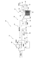
図1は、汚染水浄化システムの全体概略図で、この汚染水浄化システム10は、一次処理部12と、油分除去処理部14と、限外濾過部16と、有機化合物除去処理部18とを有する。
FIG. 1 is an overall schematic view of a contaminated water purification system. This contaminated
一次処理部12は、ダイオキシン類の汚染水の原水に対して無機物の除去処理を行うもので、遠心分離装置20または沈殿槽22を有している。
The
遠心分離装置20は、遠心力により無機物の除去を行った後凝集剤を添加して沈殿させ、その上澄み水を一次処理水槽24に貯留するようになっている。
The
沈殿槽22は、ダイオキシン類の汚染水の原水に凝集剤を添加し、無機物類を沈殿させ、その上澄み水をポンプ26にて一次処理水槽24に貯留するようになっている。
The
油分除去処理部14は、一次処理水に対し油分の除去処理を行うもので、一次処理水槽24からポンプ28にて一次処理水30をオイルフィルター32に送り、一次処理水30がオイルフィルター32を通過する際に、一次処理水30から油分を除去するようになっている。
The oil
限外濾過部16は、オイルフィルター32を通過した無機物及び油分の除去された被処理水を流量計34を通して限外濾過装置36に送り、この限外濾過装置36を通過する際に、限外濾過膜にて0.01μmまでのダイオキシン類が付着したSS分を回収するようになっている。
The
また、この限外濾過装置36は、オイルフィルター32を通過した油分の除去された被処理水を通過させるため、限外濾過膜の目詰まりを防止することができ、わずかに油分が被処理水に含まれていて目詰まりが生じた場合には、水道水等を限外濾過装置36に注入して限外濾過膜の洗浄を行い、この逆洗浄水を破線で示すように一次処理部12に戻すようにしている。
In addition, since the
有機化合物除去処理部18は、オイルフィルター32で油分が除去され、限外濾過装置36で0.01μmまでのダイオキシン類が付着したSS分の回収された被処理水に対し光触媒浄化装置38を用いて有機化合物の分解処理を行い、浄化された処理水を処理水槽40に貯留し、この処理水槽40からポンプ42にて濁度計44を通し放流するようになっている。
The organic compound
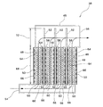
光触媒浄化装置38は、図2に示すように、処理槽46と、区画通路48と、紫色発光ダイオード50と、冷却部材としてのヒートパイプ52とを有している。
As shown in FIG. 2, the
処理槽46は、ダイオキシン類等の有機化合物に汚染された被処理水を通過させるもので、下部左側に被処理水の入口54、上部右側に出口56を有する縦長のものとされている。
The
また、この処理槽46は、全体が透明部材で形成された状態となっている。
Further, the
区画通路48は、処理槽46内における被処理水の流路を複数に分割するもので、隔壁58と、光触媒体としての光触媒を担持したシリカゲル(以下、光触媒シリカゲルと称す。)60とを有している。
The
隔壁58は、内部中空の透明な箱体からなり、処理槽46の下部側に複数、例えば3個所定間隔で縦型に配設され、処理槽46の両側壁と隔壁58との間及び隔壁58同士の間に処理水の通過領域を形成するようになっている。
The
光触媒シリカゲル60は、各区画通路48の下部側に多数充填され、その上下に金網62が配設され、この金網62によって光触媒シリカゲル60をおさえることで、処理槽46内で光触媒シリカゲル60が移動するのを防止するようにしている。
A large number of
なお、この光触媒シリカゲル60は、油分の除去された被処理水と接触するので、油分が付着して効率が低下されるのを防止できる。
In addition, since this
この光触媒シリカゲル60は、粒径が1.7〜4.0mmのものが用いられている。
As this
紫色発光ダイオード50は、例えばガラス入りエポキシ樹脂からなるリフレクター基板64を取り付けたアルミニウム製の発光ダイオード基板66に所定ピッチで複数搭載された状態となっている。
A plurality of purple
そして、光触媒シリカゲル60の充填範囲における処理槽46の外側位置及び隔壁58内に、区画通路48に向けて紫色発光ダイオード50搭載の発光ダイオード基板66が配設され、各区画通路48内の光触媒シリカゲル60に対して両側から光を照射するようになっている。
Then, a light
特に、各隔壁58内では、発光ダイオード基板66を背中合わせにして配設されるようになっている。
In particular, in each
ヒートパイプ52は、下部側が隔壁58内に挿入され、背中合わせに配設された発光ダイオード基板66間に挿入されて、発光ダイオード基板66と接触されると共に、上部側を隔壁58の上端より上方に突出させ、この上部側の突出部分を隔壁58外の被処理水と接触させて、被処理水により冷却可能にされている。
The lower side of the
このヒートパイプ52は、パイプ内に作動液として低沸点冷媒を真空封入した状態となっており、発光ダイオード基板66と接触している部分が熱により作動液が蒸発して蒸発熱を奪う蒸発部68とされ、隔壁58の上端より突出して被処理水と接触する部分が凝縮部72とされている。
The
そして、発光ダイオード基板66からの熱を吸収した作動液が蒸発部68で蒸発し、凝縮部72で凝縮されて流下し蒸発部68へと戻って循環することで冷却が行われるようになっている。
Then, the working fluid that has absorbed the heat from the light emitting
このように、ヒートパイプ52によって蒸発熱を利用した熱交換を行い、凝縮部72を被処理水自身で冷却して放熱する構造としたことで、放熱効率が向上し、紫色発光ダイオード50を密に配置して十分な照度を確保することができた。
In this way, heat exchange using the heat of evaporation is performed by the
また、処理槽46内に複数の区画通路48を形成し、区画通路48内の光触媒シリカゲル60の両側に配設した紫色発光ダイオード50によって両側から照射することで、紫外線を区画通路48の中央まで均一に照射することが可能となった。
Further, a plurality of
そして、紫色発光ダイオード50のスイッチをオンにして、紫外線を光触媒シリカゲル60に向けて照射した状態で、被処理水の入口54からダイオキシン類等の有機化合物に汚染された被処理水を処理槽46内に供給し、被処理水を光触媒シリカゲル60が充填された区画通路48内を通過させ、各区画通路48を通過した被処理水が各区画通路48で浄化された状態で上昇し、ヒートパイプ52を冷却しつつ被処理水の出口56より浄化された浄化水として被処理水が取り出されるようになっている。
Then, the water to be treated contaminated with an organic compound such as dioxins from the
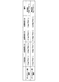
次に、この汚染水浄化システム10を用いて汚染水の浄化を行った実験結果を図4に示す。
Next, FIG. 4 shows the experimental results of purifying contaminated water using this contaminated
この実験では、汚染水の原水を1次処理を行ってダイオキシン類濃度11pg−TEQ/lの1次処理水と、ダイオキシン類濃度2.5pg−TEQ/lの1次処理水との2種類の1次処理水を準備して、それぞれ処理時間2分、処理時間8分、処理時間14分処理したものである。 In this experiment, the raw water of the contaminated water is subjected to a primary treatment, and two kinds of treatment water, a primary treatment water having a dioxin concentration of 11 pg-TEQ / l and a primary treatment water having a dioxin concentration of 2.5 pg-TEQ / l. Primary treated water is prepared and treated for a treatment time of 2 minutes, a treatment time of 8 minutes, and a treatment time of 14 minutes, respectively.
その結果、11pg−TEQ/lの1次処理水は、処理時間2分で4.3pg−TEQ/l、処理時間8分で2.7pg−TEQ/l、処理時間14分で2.3pg−TEQ/lという結果が得られ、排水基準である10pg−TEQ/lの値をいずれも下回った結果となっていた。 As a result, the primary treated water of 11 pg-TEQ / l was 4.3 pg-TEQ / l at a treatment time of 2 minutes, 2.7 pg-TEQ / l at a treatment time of 8 minutes, and 2.3 pg- at a treatment time of 14 minutes. The result of TEQ / l was obtained, and the result was lower than the value of 10 pg-TEQ / l, which is the drainage standard.
2.5pg−TEQ/lの1次処理水は、処理時間2分で0.9pg−TEQ/l、処理時間8分で2.1pg−TEQ/l、処理時間14分で1.4pg−TEQ/lという結果となり、処理時間8分及び14分の場合にいずれも環境基準1pg−TEQ/lの値を下回った結果となっている。 The primary treated water of 2.5 pg-TEQ / l is 0.9 pg-TEQ / l at a treatment time of 2 minutes, 2.1 pg-TEQ / l at a treatment time of 8 minutes, and 1.4 pg-TEQ at a treatment time of 14 minutes. As a result, the result was less than the value of the environmental standard 1 pg-TEQ / l when the processing time was 8 minutes and 14 minutes.
従って、この汚染水浄化システム10によれば、簡易な構成で、効率よくダイオキシン類等の浄化を行うことができることが判明した。
Therefore, according to this polluted
本発明は、前記実施の形態に限定されるものではなく、本発明の要旨の範囲内において種々の形態に変形可能である。 The present invention is not limited to the above-described embodiment, and can be modified into various forms within the scope of the gist of the present invention.
例えば、前記実施の形態では、油分除去処理部と有機化合物除去処理部との間に限外濾過部を設けているが、汚染の度合いによっては省略することも可能である。 For example, in the above-described embodiment, the ultrafiltration unit is provided between the oil component removal processing unit and the organic compound removal processing unit, but may be omitted depending on the degree of contamination.
また、光触媒浄化装置は、紫色発光ダイオードの冷却部材としてヒートパイプを用いたが、この例に限らず、アルミニウム製などの冷却プレートや液体や気体を媒体とした熱交換器を用いることも可能である。 The photocatalyst purification apparatus uses a heat pipe as a cooling member for the purple light emitting diode. However, the present invention is not limited to this example, and it is possible to use a cooling plate made of aluminum or a heat exchanger using a liquid or gas medium. is there.
さらに、光触媒浄化装置の処理槽は、全体が透明部材で形成されているが、この例に限らず、紫色発光ダイオードによって光触媒シリカゲルに紫外線を照射する部分が少なくとも透明部材とされていればよい。 Further, the processing tank of the photocatalyst purification apparatus is entirely formed of a transparent member. However, the present invention is not limited to this example, and it is sufficient that at least a portion that irradiates the photocatalytic silica gel with ultraviolet light by a violet light emitting diode is a transparent member.
また、光触媒体として光触媒シリカゲルを用いているが、この例に限らず、担持体として多孔質体、ガラスビーズ等を用いた光触媒体や光触媒粒等の種々の光触媒体を用いることが可能である。 Further, although photocatalytic silica gel is used as a photocatalyst, the present invention is not limited to this example, and various photocatalysts such as a photocatalyst using a porous body, glass beads, or the like, or photocatalyst particles can be used as a support. .
この光触媒体の粒径、形状は、汚染水の量、汚染の程度、区画通路の幅などによって適宜選択できる。 The particle size and shape of the photocatalyst can be appropriately selected depending on the amount of contaminated water, the degree of contamination, the width of the partition passage, and the like.
さらに、前記実施の形態では、紫色発光ダイオードを用いているが、この例に限定されるものではなく、他の波長の光を発生する発光ダイオードを用いることも可能である。 Furthermore, although the violet light-emitting diode is used in the above embodiment, the present invention is not limited to this example, and a light-emitting diode that generates light of other wavelengths can be used.
また、処理槽は、縦型に用いているが、横型に用いることも可能である。 Moreover, although the processing tank is used for the vertical type, it can also be used for the horizontal type.
さらに、被処理水の入口、出口は、上下逆にすることも可能である。 Furthermore, the inlet and outlet of the water to be treated can be turned upside down.
10 汚染水浄化システム
12 一次処理部
14 油分除去処理部
16 限外濾過部
18 有機化合物除去処理部
30 一次処理水
32 オイルフィルター
36 限外濾過装置
38 光触媒浄化装置
46 処理槽
48 区画通路
50 紫色発光ダイオード
52 ヒートパイプ
58 隔壁
60 光触媒シリカゲル
66 発光ダイオード
DESCRIPTION OF
Claims (2)
前記一次処理水に対し油分の除去処理を行う油分除去処理部と、
前記油分除去処理部で油分の除去された被処理水に対し光触媒浄化装置を用いて有機化合物の除去処理を行う有機化合物除去処理部とを有し、
前記光触媒浄化装置は、前記被処理水を通過させる処理槽内に光触媒体を収容した複数の区画通路を形成し、発光ダイオード基板に搭載された複数の発光ダイオードを各区画通路の両側に前記区画通路に向けて光を照射可能に配設し、前記発光ダイオード基板に冷却部材の一部を接触させて前記冷却部材の他部を前記被処理水によって冷却可能とされていることを特徴とする汚染水浄化システム。 A primary treatment unit that obtains primary treated water by adding a flocculant to the raw water of the contaminated water to remove inorganic substances;
An oil removal processing unit that performs an oil removal process on the primary treated water;
An organic compound removal treatment unit that performs an organic compound removal treatment on the treated water from which oil has been removed in the oil removal treatment unit, using a photocatalytic purification device;
The photocatalyst purification apparatus forms a plurality of partition passages containing a photocatalyst body in a treatment tank through which the water to be treated passes, and the plurality of light emitting diodes mounted on a light emitting diode substrate are disposed on both sides of each partition passage. It is arranged to be able to irradiate light toward the passage, and a part of the cooling member is brought into contact with the light emitting diode substrate so that the other part of the cooling member can be cooled by the water to be treated. Contaminated water purification system.
前記油分除去処理部と前記有機化合物除去処理部との間に限外濾過部が配設されていることを特徴とする汚染水浄化システム。
In claim 1,
A polluted water purification system, wherein an ultrafiltration unit is disposed between the oil removal unit and the organic compound removal unit.
Priority Applications (1)
| Application Number | Priority Date | Filing Date | Title |
|---|---|---|---|
| JP2004105981A JP2005288288A (en) | 2004-03-31 | 2004-03-31 | Contaminated water purification system |
Applications Claiming Priority (1)
| Application Number | Priority Date | Filing Date | Title |
|---|---|---|---|
| JP2004105981A JP2005288288A (en) | 2004-03-31 | 2004-03-31 | Contaminated water purification system |
Publications (1)
| Publication Number | Publication Date |
|---|---|
| JP2005288288A true JP2005288288A (en) | 2005-10-20 |
Family
ID=35321845
Family Applications (1)
| Application Number | Title | Priority Date | Filing Date |
|---|---|---|---|
| JP2004105981A Pending JP2005288288A (en) | 2004-03-31 | 2004-03-31 | Contaminated water purification system |
Country Status (1)
| Country | Link |
|---|---|
| JP (1) | JP2005288288A (en) |
Cited By (4)
| Publication number | Priority date | Publication date | Assignee | Title |
|---|---|---|---|---|
| CN102701536A (en) * | 2012-06-28 | 2012-10-03 | 苏州科博思流体科技有限公司 | Restaurant waste water processing device |
| CN104528988A (en) * | 2014-12-15 | 2015-04-22 | 中国石油天然气股份有限公司 | A gas field oil-containing alcohol-containing sewage pretreatment system and method thereof |
| WO2016056370A1 (en) * | 2014-10-09 | 2016-04-14 | 東レ株式会社 | Photoirradiation device, photoreaction method using same, and method for producing lactam |
| WO2016056371A1 (en) * | 2014-10-09 | 2016-04-14 | 東レ株式会社 | Photochemical reaction device, photochemical reaction method using same, and lactone production method using said method |
-
2004
- 2004-03-31 JP JP2004105981A patent/JP2005288288A/en active Pending
Cited By (5)
| Publication number | Priority date | Publication date | Assignee | Title |
|---|---|---|---|---|
| CN102701536A (en) * | 2012-06-28 | 2012-10-03 | 苏州科博思流体科技有限公司 | Restaurant waste water processing device |
| WO2016056370A1 (en) * | 2014-10-09 | 2016-04-14 | 東レ株式会社 | Photoirradiation device, photoreaction method using same, and method for producing lactam |
| WO2016056371A1 (en) * | 2014-10-09 | 2016-04-14 | 東レ株式会社 | Photochemical reaction device, photochemical reaction method using same, and lactone production method using said method |
| US10414724B2 (en) | 2014-10-09 | 2019-09-17 | Toray Industries, Inc. | Photochemical reaction device, photochemical reaction method using same, and lactam production method using said method |
| CN104528988A (en) * | 2014-12-15 | 2015-04-22 | 中国石油天然气股份有限公司 | A gas field oil-containing alcohol-containing sewage pretreatment system and method thereof |
Similar Documents
| Publication | Publication Date | Title |
|---|---|---|
| US10519051B2 (en) | Systems and methods for the treatment of ballast water | |
| US6136203A (en) | System and method for photocatalytic treatment of contaminated media | |
| CN102351282B (en) | Device and method for treating difficultly degraded organic waste water by plasma technology | |
| US20020096479A1 (en) | System and method for photocatalytic treatment of contaminated media | |
| KR102241219B1 (en) | Air purifier | |
| JP2005288288A (en) | Contaminated water purification system | |
| KR20240137917A (en) | Green tide removal apparatus of circulation type | |
| JP3858734B2 (en) | Water treatment equipment | |
| JP4371311B2 (en) | Organic compound contaminated water purification equipment | |
| JP3612150B2 (en) | Water treatment equipment | |
| JP2005296859A (en) | Harmful substance decomposition method and harmful substance decomposition apparatus | |
| KR20230170610A (en) | Apparatus and Method for Preventing Biofilm Formation of Membrane Filter Surface Using Effluent Water | |
| JP2005152815A (en) | Sewage treatment apparatus | |
| TWM648009U (en) | Waste water treating equipment | |
| KR101436032B1 (en) | a contaminated water treatment device and the water treatment using thereof | |
| CN1895751A (en) | Air light catalytic purifier of moderate chemical pollution | |
| JP2011177691A (en) | Air cleaner | |
| DE3907670C2 (en) | ||
| JP6882076B2 (en) | Carbon dioxide capture system and carbon dioxide capture method | |
| JP4903323B2 (en) | Hazardous substance treatment equipment and wastewater treatment system | |
| KR200407311Y1 (en) | Contaminated Water Circulation Filtration Device | |
| KR20210043122A (en) | Non-degradable Waste Water Treatment Apparatus | |
| RU2820677C1 (en) | Plant for adsorption co2 from atmospheric air using technology of thermal regeneration of sorbent | |
| JP2025176850A (en) | Hydrogen generation system and hydrogen generation method | |
| CN223936376U (en) | Integrated integrated equipment for advanced treatment of perfluorooctanoic acid wastewater |
Legal Events
| Date | Code | Title | Description |
|---|---|---|---|
| A621 | Written request for application examination |
Free format text: JAPANESE INTERMEDIATE CODE: A621 Effective date: 20070130 |
|
| A977 | Report on retrieval |
Free format text: JAPANESE INTERMEDIATE CODE: A971007 Effective date: 20090323 |
|
| A131 | Notification of reasons for refusal |
Free format text: JAPANESE INTERMEDIATE CODE: A131 Effective date: 20090401 |
|
| A02 | Decision of refusal |
Free format text: JAPANESE INTERMEDIATE CODE: A02 Effective date: 20090722 |