JP2005288266A - Separation membrane, its manufacturing method and water-treating apparatus - Google Patents
Separation membrane, its manufacturing method and water-treating apparatus Download PDFInfo
- Publication number
- JP2005288266A JP2005288266A JP2004105172A JP2004105172A JP2005288266A JP 2005288266 A JP2005288266 A JP 2005288266A JP 2004105172 A JP2004105172 A JP 2004105172A JP 2004105172 A JP2004105172 A JP 2004105172A JP 2005288266 A JP2005288266 A JP 2005288266A
- Authority
- JP
- Japan
- Prior art keywords
- polymer
- water
- separation membrane
- membrane
- adsorbed
- Prior art date
- Legal status (The legal status is an assumption and is not a legal conclusion. Google has not performed a legal analysis and makes no representation as to the accuracy of the status listed.)
- Pending
Links
Images

Landscapes
- Separation Using Semi-Permeable Membranes (AREA)
Abstract
Description
本発明は、分離膜、その製造方法及び水処理装置に関する。さらに詳しくは、本発明は、流束が大きく、優れた分離機能を有する分離膜、その製造方法及び水処理装置に関する。 The present invention relates to a separation membrane, a manufacturing method thereof, and a water treatment apparatus. More specifically, the present invention relates to a separation membrane having a large flux and an excellent separation function, a method for producing the same, and a water treatment apparatus.
現在、水処理分野においてはさまざまな処理技術による処理が行われているが、中でも膜処理は超純水製造や排水回収などの処理に欠かせない技術である。膜を透過する速度が物質により異なると、混合物を分離することができ、この性質は膜の選択透過性又は分離機能と呼ばれる。このような選択透過性は、膜と透過する物質との相互作用によって決まる。相互作用には、細孔による篩い分け作用と、物質の膜内への溶解、拡散などの物理化学的な作用とがある。
膜処理に用いられる分離膜としては、精密ろ過膜、限外ろ過膜、逆浸透膜などが用いられている。一般的に、膜分離では、圧力をかけて膜を透過した水を押し出すことにより、水中の分離対象物を膜面で排除して処理水を得るが、分離対象物が小さくなるほど、膜の細孔径を小さくする必要があり、水を押し出すためには高い圧力が必要となる。このために、他の物理化学的な作用を利用して、低い圧力で水を押し出し、流束を低下させることなく、高い分離機能が発現する分離膜が求められている。
空気清浄機などに利用できる集塵、集煙機能をもち、特に、煙や匂いの素となる粒子、分子又はイオンが侵入可能な空洞構造をなし、正の電荷をもった第1の帯電膜と、負の電荷をもった第2の帯電膜とを、基材上に交互に吸着させてなる交互吸着膜を用いたフィルターと、該フィルターとフィルターに水を通すためのろ過機構とを有する水処理装置が提案され、食塩水から純水を得るための装置が開示されている(特許文献1)。しかし、このフィルターでは、正電荷を帯びた粒子が負の帯電膜中に吸着され、負電荷を帯びた粒子が正の帯電膜中に吸着され、吸着はクーロン力に基く物理的な作用によるので、飽和状態に達すると、それ以上の粒子を吸着することは不可能である。煙の粒子で飽和に達したフィルターを90℃の温水で3分間洗浄すると、吸着されていた煙の粒子はほとんど離脱し、吸着効率は著しく回復することが報告されているが、このフィルターを分離膜として長期的に使用することは不可能である。
As a separation membrane used for membrane treatment, a microfiltration membrane, an ultrafiltration membrane, a reverse osmosis membrane, or the like is used. In general, in membrane separation, water that has permeated through the membrane is pushed out by applying pressure to remove the separation target in water at the membrane surface to obtain treated water. However, the smaller the separation target, the smaller the membrane. It is necessary to reduce the pore diameter, and high pressure is required to extrude water. For this reason, there is a need for a separation membrane that exhibits a high separation function without extruding water at a low pressure by using another physicochemical action and reducing the flux.
A first charged film having a positive charge that has a dust collection and smoke collection function that can be used in an air cleaner, etc., and that has a hollow structure in which particles, molecules, or ions that can be a source of smoke and odors can enter. And a filter using an alternately adsorbing film formed by alternately adsorbing a second charged film having a negative charge on a substrate, and a filter mechanism for passing water through the filter and the filter A water treatment apparatus has been proposed, and an apparatus for obtaining pure water from saline is disclosed (Patent Document 1). However, in this filter, positively charged particles are adsorbed in the negatively charged film, negatively charged particles are adsorbed in the positively charged film, and the adsorption is due to physical action based on Coulomb force. Once saturated, it is impossible to adsorb any more particles. It has been reported that when a filter that has reached saturation with smoke particles is washed with warm water at 90 ° C for 3 minutes, most of the adsorbed smoke particles are released and the adsorption efficiency is significantly recovered. Long-term use as a membrane is impossible.
本発明は、流束が大きく、優れた分離機能を有する分離膜、その製造方法及び水処理装置を提供することを目的としてなされたものである。 An object of the present invention is to provide a separation membrane having a large flux and an excellent separation function, a method for producing the same, and a water treatment apparatus.
本発明者らは、上記の課題を解決すべく鋭意研究を重ねた結果、カチオンポリマーとアニオンポリマーとが結合して形成されるポリイオンコンプレックスを透水性支持材上に層状に保持してなる分離膜において、カチオンポリマーとアニオンポリマーの少なくとも一方を剛直鎖構造を有する高分子とすることにより、流束を低下させることなく、分離機能を向上し得ることを見いだし、この知見に基づいて本発明を完成するに至った。
すなわち、本発明は、
(1)カチオンポリマーとアニオンポリマーとが結合して形成されるポリイオンコンプレックスを透水性支持材上に層状に保持してなる分離膜であって、カチオンポリマーとアニオンポリマーの少なくとも一方が剛直鎖構造を有する高分子であることを特徴とする分離膜、
(2)剛直鎖構造を有する高分子が、DNAである(1)記載の分離膜、
(3)透水性支持材の平均細孔径が、0.1〜10μmである(1)記載の分離膜、
(4)透水性支持材上に、カチオンポリマーとアニオンポリマーとを交互に吸着させることにより、透水性支持材上にカチオンポリマーとアニオンポリマーとが結合して形成されるポリイオンコンプレックスを層状に保持してなり、カチオンポリマーとアニオンポリマーの少なくとも一方が剛直鎖構造を有する高分子である分離膜を製造する方法であって、一方の電荷を有する高分子を吸着させる工程と、他方の電荷を有する高分子を吸着させる工程との間に、吸着された高分子膜層を乾燥させる工程を有することを特徴とする分離膜の製造方法、
(5)(1)〜(3)のいずれか1項に記載の分離膜と、該分離膜の一方の側に原水を供給する手段と、該分離膜の他方の側から処理水を取り出す手段とを備えてなることを特徴とする水処理装置、及び、
(6)(5)において、該分離膜の静電的反発作用により原水中の溶解性物質の透過を排除することにより脱塩処理する水処理装置であって、該分離膜に吸着されたポリイオンコンプレックスがイオンを飽和吸着した後も連続通水により脱塩率10%以上の処理水を得ることを特徴とする水処理装置、
を提供するものである。
As a result of intensive studies to solve the above-mentioned problems, the present inventors have obtained a separation membrane in which a polyion complex formed by combining a cationic polymer and an anionic polymer is held in a layer on a water-permeable support material. In the present invention, it has been found that the separation function can be improved without lowering the flux by making at least one of the cationic polymer and the anionic polymer a polymer having a rigid linear structure, and the present invention has been completed based on this finding. It came to do.
That is, the present invention
(1) A separation membrane in which a polyion complex formed by combining a cationic polymer and an anionic polymer is held in a layer on a water-permeable support material, and at least one of the cationic polymer and the anionic polymer has a rigid linear structure A separation membrane characterized by being a polymer having,
(2) The separation membrane according to (1), wherein the polymer having a rigid linear structure is DNA,
(3) The separation membrane according to (1), wherein the water-permeable support material has an average pore diameter of 0.1 to 10 μm,
(4) By alternately adsorbing the cationic polymer and the anionic polymer on the water-permeable support material, the polyion complex formed by combining the cationic polymer and the anionic polymer on the water-permeable support material is held in a layered form. A method for producing a separation membrane in which at least one of a cationic polymer and an anionic polymer is a polymer having a rigid linear structure, comprising a step of adsorbing a polymer having one charge and a high charge having the other charge. A method for producing a separation membrane, comprising a step of drying the adsorbed polymer membrane layer between the step of adsorbing molecules,
(5) The separation membrane according to any one of (1) to (3), means for supplying raw water to one side of the separation membrane, and means for taking out treated water from the other side of the separation membrane And a water treatment device characterized by comprising:
(6) In (5), a water treatment apparatus for desalinating by eliminating permeation of soluble substances in raw water by electrostatic repulsion of the separation membrane, wherein the polyion adsorbed on the separation membrane A water treatment apparatus characterized in that after the complex has saturatedly adsorbed ions, treated water having a desalination rate of 10% or more is obtained by continuous water flow;
Is to provide.
本発明の分離膜は、選択透過性に優れ、本発明の分離膜又は水処理装置を用いることにより、従来の逆浸透膜などを用いる膜分離及び水処理装置に比べて、低い圧力で、大きい流束と高い脱塩率を得ることができる。 The separation membrane of the present invention is excellent in permselectivity, and by using the separation membrane or water treatment device of the present invention, it is large at a lower pressure than a conventional membrane separation and water treatment device using a reverse osmosis membrane or the like. Flux and high desalination rate can be obtained.
本発明の分離膜は、カチオンポリマーとアニオンポリマーとが結合して形成されるポリイオンコンプレックスを透水性支持材上に層状に保持してなる分離膜であって、カチオンポリマーとアニオンポリマーの少なくとも一方が剛直鎖構造を有する高分子である分離膜である。
本発明に用いるカチオンポリマーには、ハロゲン化物イオンなどを対イオンとして正の電荷を有する高分子のみならず、ハロゲン化水素などと反応して塩を形成し、正の電荷を有する状態となる得る高分子も含まれる。本発明に用いるカチオンポリマーとしては、例えば、ポリエチレンイミン、ポリビニルアミン、ポリアリルアミン又はこれらのハロゲン化水素塩、硫酸塩、硝酸塩、ポリオルニチン、ポリリジンなどのポリアミノ酸又はこれらの塩、ポリ(ハロゲン化ジアリルジアルキルアンモニウム)、ジアルキルアミンとエピハロヒドリンとの縮合物、N,N,N',N'−テトラアルキルジアミンとジハロゲン化物との付加反応により生成する高分子などを挙げることができる。
本発明に用いるアニオンポリマーには、アルカリ金属イオンなどを対イオンとして負の電荷を有する高分子のみならず、アルカリ金属の水酸化物などと反応して塩を形成し、負の電荷を有する状態となる得る高分子も含まれる。本発明に用いるアニオンポリマーとしては、例えば、ポリアクリル酸、ポリメタクリル酸、ポリスチレンスルホン酸、ポリ(2−アクリルアミド−2−メチルプロパンスルホン酸)、DNA(デオキシリボ核酸)又はこれらのアルカリ金属塩などを挙げることができる。
The separation membrane of the present invention is a separation membrane in which a polyion complex formed by combining a cationic polymer and an anionic polymer is held in a layer on a water-permeable support material, and at least one of the cationic polymer and the anionic polymer is It is a separation membrane which is a polymer having a rigid linear structure.
The cationic polymer used in the present invention is not only a polymer having a positive charge with a halide ion or the like as a counter ion, but also reacts with hydrogen halide or the like to form a salt, and can have a positive charge. Polymers are also included. Examples of the cationic polymer used in the present invention include polyethyleneimine, polyvinylamine, polyallylamine, or hydrogen halides thereof, sulfates, nitrates, polyornithine, polylysine and other polyamino acids or salts thereof, and poly (diallyl halide). Dialkylammonium), a condensate of dialkylamine and epihalohydrin, and a polymer formed by addition reaction of N, N, N ′, N′-tetraalkyldiamine and dihalide.
The anionic polymer used in the present invention is not only a polymer having a negative charge with an alkali metal ion or the like as a counter ion, but also forms a salt by reacting with an alkali metal hydroxide or the like to have a negative charge. Also included are polymers that can be Examples of the anionic polymer used in the present invention include polyacrylic acid, polymethacrylic acid, polystyrene sulfonic acid, poly (2-acrylamido-2-methylpropane sulfonic acid), DNA (deoxyribonucleic acid), or alkali metal salts thereof. Can be mentioned.
本発明において、剛直鎖構造を有する高分子とは、溶液中でランダムコイルほど自由に屈曲することができない高分子をいう。剛直鎖構造を有する高分子としては、例えば、ポリイソシアネート、芳香族ポリアミド、二重螺旋DNA、セルロース誘導体などを挙げることができる。剛直鎖構造を有する高分子は、水素結合、共役二重結合などにより内部回転が極度に束縛された鎖、内部回転が自由でも180度に近い結合角で連結された鎖などから構成される。
本発明に用いる剛直鎖構造を有するカチオンポリマーとしては、例えば、式[1]で表されるN,N,N',N'−テトラメチル−p−フェニレンジアミンと1,2−ジクロロエタンの付加反応により生成する高分子などを挙げることができる。

Examples of the cationic polymer having a rigid linear structure used in the present invention include addition reaction of N, N, N ′, N′-tetramethyl-p-phenylenediamine represented by the formula [1] and 1,2-dichloroethane. And the like.
本発明に用いる透水性支持材は、平均細孔径が0.1〜10μmであることが好ましく、0.2〜5μmであることがより好ましい。平均細孔径が0.1μm未満であると、分離膜の流束が小さくなりすぎるおそれがある。平均細孔径が10μmを超えると、分離膜の分離機能が低下するおそれがある。本発明に用いる透水性支持材の厚さに特に制限はないが、0.01〜1mmであることが好ましく、0.05〜0.5mmであることがより好ましい。本発明に用いる透水性支持材の材質に特に制限はなく、例えば、酢酸セルロース、三酢酸セルロース、ニトロセルロース、再生セルロース、ゼラチン、芳香族ポリアミド、アクリロニトリル−塩化ビニル共重合体、ポリスルホン、ポリカーボネート、ポリエステル、ポリテトラフルオロエチレン、ポリフッ化ビニリデン、ポリプロピレンなどを挙げることができる。透水性支持材の形状に特に制限はなく、例えば、平面膜、スパイラル、管型、中空糸などを挙げることができる。管型、中空糸などは、それらの外側に高分子膜層を積層し、外圧型の分離膜として用いることが好ましい。 The water-permeable support material used in the present invention preferably has an average pore diameter of 0.1 to 10 μm, and more preferably 0.2 to 5 μm. If the average pore diameter is less than 0.1 μm, the flux of the separation membrane may be too small. When the average pore diameter exceeds 10 μm, the separation function of the separation membrane may be deteriorated. Although there is no restriction | limiting in particular in the thickness of the water-permeable support material used for this invention, It is preferable that it is 0.01-1 mm, and it is more preferable that it is 0.05-0.5 mm. The material of the water-permeable support material used in the present invention is not particularly limited. For example, cellulose acetate, cellulose triacetate, nitrocellulose, regenerated cellulose, gelatin, aromatic polyamide, acrylonitrile-vinyl chloride copolymer, polysulfone, polycarbonate, polyester , Polytetrafluoroethylene, polyvinylidene fluoride, polypropylene and the like. There is no restriction | limiting in particular in the shape of a water-permeable support material, For example, a plane membrane, a spiral, a pipe type, a hollow fiber etc. can be mentioned. The tube type, hollow fiber, etc. are preferably used as an external pressure type separation membrane by laminating a polymer membrane layer on the outside thereof.
本発明の分離膜の製造方法は、透水性支持材上に、カチオンポリマーとアニオンポリマーとを交互に吸着させることにより、透水性支持材上にカチオンポリマーとアニオンポリマーとが結合して形成されるポリイオンコンプレックスを層状に保持してなり、カチオンポリマーとアニオンポリマーの少なくとも一方が剛直鎖構造を有する高分子である分離膜を製造する方法であって、一方の電荷を有する高分子を吸着させる工程と、他方の電荷を有する高分子を吸着させる工程との間に、吸着された高分子膜層を乾燥させる工程を有する。
本発明方法において、透水性支持材上に、正の電荷又は負の電荷を有する高分子を吸着させる方法に特に制限はなく、例えば、透水性支持材の表面を正又は負に帯電させたのち、帯電した電荷と異符号の電荷を有する高分子水溶液と接触させることにより、負又は正の電荷を有する高分子を疎水性支持材の表面に吸着させ、第一の高分子膜層を形成することができる。負又は正の電荷を有する高分子膜層を形成したのち、純水などを用いて高分子膜層を洗浄することが好ましい。高分子膜層を洗浄しないと、緊密に高分子膜層に取り込まれていない高分子が高分子膜層の表面に残存し、乾燥により緻密な高分子膜層を形成する妨げになる。
In the method for producing a separation membrane of the present invention, the cationic polymer and the anionic polymer are alternately adsorbed on the water-permeable support material, whereby the cationic polymer and the anionic polymer are combined on the water-permeable support material. A method for producing a separation membrane in which a polyion complex is held in a layer and at least one of a cationic polymer and an anionic polymer is a polymer having a rigid linear structure, the method comprising the step of adsorbing one charged polymer And a step of drying the adsorbed polymer film layer between the step of adsorbing the other charged polymer.
In the method of the present invention, there is no particular limitation on the method of adsorbing a polymer having a positive charge or a negative charge on the water permeable support material. For example, after the surface of the water permeable support material is positively or negatively charged. The first polymer membrane layer is formed by adsorbing the polymer having a negative or positive charge on the surface of the hydrophobic support material by contacting with a polymer aqueous solution having a charge different from that of the charged charge. be able to. After forming a polymer film layer having a negative or positive charge, it is preferable to wash the polymer film layer using pure water or the like. If the polymer film layer is not washed, the polymer that has not been tightly taken into the polymer film layer remains on the surface of the polymer film layer, which hinders the formation of a dense polymer film layer by drying.
本発明方法においては、一方の電荷を有する高分子を吸着させる工程と、他方の電荷を有する高分子を吸着させる工程との間に、吸着された高分子膜層を乾燥させる工程を設ける。乾燥工程の実施の態様に特に制限はなく、例えば、50〜90℃の温風を1〜10分間当てることにより、高分子膜層を乾燥することができる。高分子膜層の厚さは薄いので、温和な条件で容易に乾燥することができる。吸着された高分子膜層を乾燥することなく、異符号の電荷を有する高分子を吸着させると、高分子膜層が水分を含んだまま積層され、最後に水分が抜けて乾燥するときに、水分の存在した場所が空隙となり、積層された高分子膜層が疎な構造となるおそれがある。また、水分を含んだ高分子膜層内の高分子は、乾燥した高分子膜層内の高分子に比べて動きやすいので、異符号の電荷を有する高分子からなる高分子膜層の境界において、正の電荷を有する高分子と負の電荷を有する高分子が絡み合い、イオン性が失われた高分子が形成されるおそれがある。吸着された高分子膜層を乾燥することにより、緻密な高分子膜層を形成する。
本発明方法において、積層するカチオンポリマーからなる高分子膜層と、アニオンポリマーからなる高分子膜層の層数に特に制限はないが、それぞれの高分子膜層数が各1〜30層、合計して2〜60層であることが好ましく、それぞれの高分子膜層数が各3〜20層、合計して6〜40層であることがより好ましい。それぞれの高分子膜層の厚さに特に制限はないが、0.1〜20nmであることが好ましく、3〜12nmであることがより好ましい。
本発明の分離膜は上記製造方法に特に限定されず、例えば透水性支持材に、カチオンポリマーとアニオンポリマーとを混合状態で吸着或いは保持させることにより、透水性支持材上にカチオンポリマーとアニオンポリマーとが均一に分散されたポリイオンコンプレックス層を層状に保持させてもよい。この場合は、例えば、カチオンポリマー水溶液とアニオンポリマー水溶液とを混合した溶液に透水性支持材を浸漬することによってポリイオンコンプレックス層が形成される。
このような方法によって得られた分離膜においても、ポリイオンコンプレックス層の厚さと層数に特に制限はないが、ポリイオンコンプレックス層の層数は10〜100層、総層厚100〜1,000nm程度であることが好ましい。
In the method of the present invention, a step of drying the adsorbed polymer film layer is provided between the step of adsorbing the polymer having one charge and the step of adsorbing the polymer having the other charge. There is no restriction | limiting in particular in the embodiment of a drying process, For example, a polymer film layer can be dried by applying 50-90 degreeC warm air for 1 to 10 minutes. Since the polymer film layer is thin, it can be easily dried under mild conditions. Without adsorbing the adsorbed polymer film layer, when adsorbing a polymer having a charge with a different sign, the polymer film layer is laminated while containing moisture, and finally when moisture is removed and dried, There is a possibility that a place where moisture exists becomes a void, and a laminated polymer film layer has a sparse structure. In addition, since the polymer in the polymer film layer containing moisture is easier to move than the polymer in the dried polymer film layer, at the boundary of the polymer film layer composed of polymers having different signs of charges. The polymer having a positive charge and the polymer having a negative charge may be entangled to form a polymer having lost ionicity. By drying the adsorbed polymer film layer, a dense polymer film layer is formed.
In the method of the present invention, there is no particular limitation on the number of polymer film layers composed of the cationic polymer and the polymer film layer composed of the anion polymer, but the number of each polymer film layer is 1 to 30 in total. The number of polymer film layers is preferably 3 to 20 layers, and more preferably 6 to 40 layers in total. Although there is no restriction | limiting in particular in the thickness of each polymer film layer, It is preferable that it is 0.1-20 nm, and it is more preferable that it is 3-12 nm.
The separation membrane of the present invention is not particularly limited to the above production method. For example, the cationic polymer and the anionic polymer are adsorbed or held on the water-permeable support material by adsorbing or holding the cationic polymer and the anion polymer in a mixed state. Alternatively, a polyion complex layer in which and are uniformly dispersed may be held in a layer shape. In this case, for example, the polyion complex layer is formed by immersing the water-permeable support material in a solution obtained by mixing a cationic polymer aqueous solution and an anionic polymer aqueous solution.
In the separation membrane obtained by such a method, the thickness and the number of layers of the polyion complex layer are not particularly limited, but the number of polyion complex layers is 10 to 100 layers, and the total layer thickness is about 100 to 1,000 nm. Preferably there is.
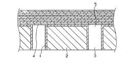
本発明においては、疎水性支持材上に層状に保持するポリイオンコンプレックスを形成させるカチオンポリマーとアニオンポリマーの少なくとも一方が、剛直鎖構造を有する高分子である。剛直鎖構造を有する高分子は、透水性支持材の細孔においては、細孔の開口部に橋を架けた状態で吸着又は保持される。細孔の開口部に剛直鎖構造を有する高分子の橋が形成されると、それ以降に吸着又は保持される高分子は剛直鎖構造を有する高分子の橋に引っかかり、細孔の内部へ侵入しない。図1は、本発明の分離膜の一態様の模式的断面図である。本態様においては、最初に疎水性支持材に吸着される高分子は剛直鎖構造を有しない高分子1であるために、疎水性支持材2の細孔3の内部に侵入し、細孔の内部の表面にも吸着される。次いで吸着される異符号の電荷を有する高分子は、剛直性構造を有する高分子4であるために、細孔の開口部5に橋を架け、細孔の内部に侵入しない。三番目に吸着される剛直性構造を有しない高分子も、橋を架けた剛直性構造を有する高分子に引っかかり、細孔の内部には侵入しない。細孔の内部に吸着された高分子は、分離機能に寄与しないので、本発明によれば、細孔の内部に吸着される正又は負の電荷を有する高分子の量を減らし、使用する高分子を有効に利用することができる。また、細孔の内部に高分子が吸着されると、細孔の実効径が小さくなって流束の低下を招くが、本発明方法によって細孔の内部に吸着される高分子の量を減らすことにより、透水性支持材が本来有する細孔径を保ち、流束の低下を防ぐことができる。
In the present invention, at least one of a cationic polymer and an anionic polymer that form a polyion complex held in a layered form on a hydrophobic support material is a polymer having a rigid linear structure. The polymer having a rigid linear structure is adsorbed or held in the pores of the water-permeable support material in a state where a bridge is bridged at the opening of the pore. When a polymer bridge having a rigid linear structure is formed at the opening of the pore, the polymer adsorbed or retained thereafter is caught by the polymer bridge having the rigid linear structure and enters the inside of the pore. do not do. FIG. 1 is a schematic cross-sectional view of one embodiment of the separation membrane of the present invention. In this embodiment, since the polymer that is first adsorbed on the hydrophobic support material is the polymer 1 that does not have a rigid linear structure, the polymer penetrates into the pores 3 of the
本発明においては、剛直鎖構造を有する高分子の疎水性支持材上への吸着又は保持を最初の数層のみにとどめ、透水性支持材に近い高分子膜層のみを剛直鎖構造を有する高分子からなる高分子膜層とし、以降は剛直鎖構造を有しない高分子からなる高分子膜層とすることもできる。
本発明の分離膜は、カチオンポリマーとアニオンポリマーとが結合して形成されるポリイオンコンプレックスが層状に積層されている。水中の正の電荷を有する粒子又は負の電荷を有する粒子は、本発明の分離膜のクーロン力により反発され、分離膜の透過を阻止されるので、高い脱塩率を発現することができる。また、高分子膜層の組織が緻密なので、帯電していない微粒子に対しても高い阻止効果を得ることができる。
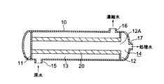
次に本発明の分離膜を用いた水処理装置について図3を参照して説明する。
図3は本発明の水処理装置の実施の形態を示す概略的な断面図である。
この水処理装置では、容器(ベッセル)10内の両端部に仕切板11、12が設けられ、原水室13と処理水室14とが形成されている。原水室13には、仕切板11、12間に中空管状の分離膜エレメント20が懸架されている。一方の仕切板12には、開口12Aが設けられ、分離膜エレメント20の一端側は、この開口12A部に取り付けられ、分離膜エレメント20の中空管内が処理水室14に連通している。15は原水の導入口、16は濃縮水の取出口、17は処理水の取出口である。
導入口15からこの水処理装置に導入された原水は、例えば図1に記載の分離膜の高分子膜層上をクロスフロー方式で流れ、この分離膜エレメント20の高分子膜の積層方向に通過し、その間にイオン及びSSが除去される。高分子膜層を通過した処理水は、分離膜エレメント20の中空部から処理水室14を経て処理水取出口17から取り出される。一方、膜で排除されたイオンやSSが濃縮された濃縮水は濃縮水取出口16から取り出される。この濃縮水は、必要に応じて一部を原水導入側に戻して循環処理し、残部を系外へ取り出すようにしても良い。
図3には、中空管状の分離膜エレメント20を設けた水処理装置を示したが、本発明の水処理装置の分離膜の型式には特に制限はなく、中空糸膜であっても平膜であっても良い。単位体積当たりの膜の表面積を大きく確保する点では中空糸膜が好ましい。いずれの形式の膜も容器内に収容し、原水を加圧して容器に供給する加圧給水型とすることが好ましいが、開放系の水中に分離膜を浸漬し、処理水側を減圧して処理水を得る浸漬型であっても良い。このときの給水圧力や減圧の程度についても特に制限はなく、膜を通して所望の処理水量が得られるように適宜決定される。また、平膜は、プレートアンドフレーム型で使用しても、スパイラル型で使用しても良い。それらの膜形式、装置形式は、精密濾過膜装置、限外濾過膜装置、逆浸透膜装置におけるものと同様であり、それらの既知の技術を転用して本発明の水処理装置を組み立てることができる。
分離膜への通水方式についても特に制限はなく、クロスフロー(平行流濾過)方式でもデッドエンド方式でも、いずれも適用可能であるが、デッドエンド方式では膜が目詰まりする可能性があるため、クロスフロー方式を採用することが好ましい。
本発明の水処理装置では、クーロン力による反発作用で脱イオンを行うので、原水を連続的に供給すると共に、処理水を連続して排出して処理を行うことが好ましい。しかして、長期間の連続通水により分離膜の表面がSS成分等で汚染され、通水抵抗が所定値以上に上昇するときには、膜面洗浄を実施することが望ましい。
本発明の水処理装置を脱塩装置として使用する場合、連続通水において脱塩率10%以上、好ましくは50%以上、より好ましくは70%以上が得られるように分離膜を設計する。そのために分離膜の高分子膜の積層数や厚さを変化させても良い。また、より緻密で細孔径の小さい分離膜を採用して脱塩率の高い装置とすることができる。
本発明の分離膜は、透水性支持材上に積層されたポリイオンコンプレックス層のクーロン力の反発作用により、水中のイオンの通過を阻止して脱イオン効果を得るものであるために、従来の逆浸透膜などに比べて、細孔径を大きくすること及び/又は膜厚を薄くすることができる。その結果、高い脱塩率を維持したまま処理圧力を低下させ、流束を向上させる分離膜及び水処理装置を提供することができる。
In the present invention, adsorption or retention of a polymer having a rigid linear structure on the hydrophobic support material is limited to only the first few layers, and only the polymer membrane layer close to the water-permeable support material has a high linear structure. A polymer film layer made of molecules can be used, and thereafter, a polymer film layer made of a polymer having no rigid linear structure can be used.
In the separation membrane of the present invention, polyion complexes formed by combining a cationic polymer and an anionic polymer are laminated in layers. The positively charged particles or the negatively charged particles in water are repelled by the Coulomb force of the separation membrane of the present invention and are prevented from passing through the separation membrane, so that a high desalting rate can be expressed. Further, since the structure of the polymer film layer is dense, a high blocking effect can be obtained even for fine particles that are not charged.
Next, a water treatment apparatus using the separation membrane of the present invention will be described with reference to FIG.
FIG. 3 is a schematic sectional view showing an embodiment of the water treatment apparatus of the present invention.
In this water treatment apparatus,
The raw water introduced into the water treatment apparatus from the
FIG. 3 shows a water treatment apparatus provided with a hollow tubular
There is no particular restriction on the water flow method to the separation membrane, and both the cross flow (parallel flow filtration) method and the dead end method can be applied. However, the dead end method may clog the membrane. It is preferable to adopt a cross flow method.
In the water treatment apparatus of the present invention, since deionization is performed by a repulsive action by Coulomb force, it is preferable to perform the treatment by continuously supplying raw water and continuously discharging the treated water. Therefore, when the surface of the separation membrane is contaminated with SS components and the like due to long-term continuous water flow, and the water flow resistance rises to a predetermined value or more, it is desirable to perform membrane surface cleaning.
When the water treatment apparatus of the present invention is used as a desalination apparatus, the separation membrane is designed so that a desalination rate of 10% or more, preferably 50% or more, more preferably 70% or more is obtained in continuous water flow. Therefore, the number and thickness of the polymer membranes of the separation membrane may be changed. Further, a denser and smaller pore size separation membrane can be employed to provide a device with a high desalting rate.
The separation membrane of the present invention has a deionizing effect by preventing the passage of ions in water by the repulsive action of the Coulomb force of the polyion complex layer laminated on the water permeable support material. Compared to an osmotic membrane or the like, the pore diameter can be increased and / or the film thickness can be decreased. As a result, it is possible to provide a separation membrane and a water treatment apparatus that reduce the treatment pressure while maintaining a high desalination rate and improve the flux.
以下に、実施例を挙げて本発明をさらに詳細に説明するが、本発明はこれらの実施例によりなんら限定されるものではない。
実施例1
透水性支持材として精密ろ過膜[日本ミリポア(株)、メンブレンフィルター、HAWP047 00、平膜、細孔径0.45μm、直径47mm]、正の電荷を有する高分子としてポリ−N−ビニルホルムアミドの加水分解により得られた重量平均分子量370万のポリビニルアミンの塩酸塩、負の電荷を有する高分子として、剛直鎖構造を有するDNA[和光純薬工業(株)、サケ精液製]を用いて、分離膜を作製した。
図2に示す膜固定容器6の支持板7上に、精密ろ過膜8の片面のみに高分子が吸着されるように載置し、支持棒9で押さえた。ポリビニルアミンの塩酸塩の1.5g/L水溶液を容器に注入し、1分間静置してポリビニルアミンの塩酸塩を精密ろ過膜の表面に吸着させたのち排出し、膜面を純水で洗浄し、ドライヤーで温風を5分間送って乾燥させた。次いで、DNAの1g/L水溶液を容器に注入し、1分間静置してDNAを吸着させたのち排出し、膜面を純水で洗浄し、ドライヤーで温風を5分間送って乾燥させた。さらに、ポリビニルアミンの塩酸塩の吸着とDNAの吸着を4回ずつ交互に繰り返し、合計して10層の高分子膜層が積層された分離膜を得た。
得られた分離膜を平膜試験装置の小径平膜セルに取り付け、脱塩性能を評価した。硫酸マグネシウムの1g/L水溶液を試料水とし、流量1.4mL/min、圧力0.45MPaでセルに導入し、4時間通水した。
透過水の電気伝導率は511μS/cmであり、濃縮水の電気伝導率は852μS/cmであり、(1−(透過水の電気伝導率/濃縮水の電気伝導率))×100(%)として求めた脱塩率は40%であった。4時間後の流束は0.525m/dayであり、1.2MPaに換算した流束は1.40m/dayであった。
実施例2
実施例1と同様にして、ポリビニルアミンの塩酸塩の吸着とDNAの吸着を8回ずつ交互に繰り返し、合計して16層の高分子膜層が積層された分離膜を得た。
試験水の圧力を0.69MPaとした以外は、実施例1と同様にして、得られた分離膜の脱塩性能を評価した。透過水の電気伝導率は394μS/cmであり、濃縮水の電気伝導率は839μS/cmであり、脱塩率は53%であった。4時間後の1.2MPaに換算した流束は、1.22m/dayであった。
実施例3
実施例1と同様にして、ポリビニルアミンの塩酸塩の吸着とDNAの吸着を10回ずつ交互に繰り返し、合計して20層の高分子膜層が積層された分離膜を得た。
試験水の圧力を1.2MPaとした以外は、実施例1と同様にして、得られた分離膜の脱塩性能を評価した。透過水の電気伝導率は268μS/cmであり、濃縮水の電気伝導率は893μS/cmであり、脱塩率は70%であった。4時間後の流束は、0.78m/dayであった。
Hereinafter, the present invention will be described in more detail with reference to examples, but the present invention is not limited to these examples.
Example 1
Microfiltration membrane [Nippon Millipore Corporation, membrane filter, HAWP04700, flat membrane, pore diameter 0.45 μm, diameter 47 mm] as water-permeable support material, and water of poly-N-vinylformamide as a positively charged polymer Separation using polyvinylamine hydrochloride with a weight average molecular weight of 3.7 million obtained by decomposition, DNA having a rigid linear structure [manufactured by Wako Pure Chemical Industries, Ltd., salmon semen] as a negatively charged polymer A membrane was prepared.
The polymer was placed on the
The obtained separation membrane was attached to a small-diameter flat membrane cell of a flat membrane test apparatus, and the desalting performance was evaluated. A 1 g / L aqueous solution of magnesium sulfate was used as sample water, introduced into the cell at a flow rate of 1.4 mL / min and a pressure of 0.45 MPa, and allowed to pass through for 4 hours.
The electric conductivity of the permeated water is 511 μS / cm, the electric conductivity of the concentrated water is 852 μS / cm, and (1− (the electric conductivity of the permeated water / the electric conductivity of the concentrated water)) × 100 (%) The desalting rate determined as was 40%. The flux after 4 hours was 0.525 m / day, and the flux converted to 1.2 MPa was 1.40 m / day.
Example 2
In the same manner as in Example 1, the adsorption of polyvinylamine hydrochloride and the adsorption of DNA were alternately repeated 8 times each to obtain a separation membrane in which a total of 16 polymer membrane layers were laminated.
The desalting performance of the obtained separation membrane was evaluated in the same manner as in Example 1 except that the test water pressure was 0.69 MPa. The electric conductivity of the permeated water was 394 μS / cm, the electric conductivity of the concentrated water was 839 μS / cm, and the desalting rate was 53%. The flux converted to 1.2 MPa after 4 hours was 1.22 m / day.
Example 3
In the same manner as in Example 1, the adsorption of polyvinylamine hydrochloride and the adsorption of DNA were alternately repeated 10 times each to obtain a separation membrane in which a total of 20 polymer membrane layers were laminated.
The desalting performance of the obtained separation membrane was evaluated in the same manner as in Example 1, except that the test water pressure was 1.2 MPa. The electric conductivity of the permeated water was 268 μS / cm, the electric conductivity of the concentrated water was 893 μS / cm, and the desalting rate was 70%. The flux after 4 hours was 0.78 m / day.
比較例1
負の電荷を有する高分子として、DNAの代わりに、ポリスチレンスルホン酸ナトリウム[東ソー(株)、商品名PS−100、重量平均分子量100万]を用いた以外は、実施例1と同様にして、ポリビニルアミンの塩酸塩の吸着とDNAの吸着を5回ずつ交互に繰り返し、合計して10層の高分子膜層が積層された分離膜を得た。
得られた分離膜を平膜試験装置の小径平膜セルに取り付け、脱塩性能を評価した。硫酸マグネシウムの1g/L水溶液を試料水とし、流量1.4mL/min、圧力0.06MPaでセルに導入し、4時間通水した。
透過水の電気伝導率は784μS/cmであり、濃縮水の電気伝導率は792μS/cmであり、脱塩率は1%であった。4時間後の流束は0.54m/dayであり、1.2MPaに換算した流束は10.8m/dayであった。
比較例2
比較例1と同様にして、ポリビニルアミンの塩酸塩の吸着とポリスチレンスルホン酸ナトリウムの吸着を8回ずつ交互に繰り返し、合計して16層の高分子膜層が積層された分離膜を得た。
試験水の圧力を0.08MPaとした以外は、実施例1と同様にして、得られた分離膜の脱塩性能を評価した。透過水の電気伝導率は732μS/cmであり、濃縮水の電気伝導率は755μS/cmであり、脱塩率は3%であった。4時間後の1.2MPaに換算した流束は、12.6m/dayであった。
比較例3
比較例1と同様にして、ポリビニルアミンの塩酸塩の吸着とポリスチレンスルホン酸ナトリウムの吸着を10回ずつ交互に繰り返し、合計して20層の高分子膜層が積層された分離膜を得た。
試験水の圧力を0.1MPaとした以外は、実施例1と同様にして、得られた分離膜の脱塩性能を評価した。透過水の電気伝導率は755μS/cmであり、濃縮水の電気伝導率は763μS/cmであり、脱塩率は3%であった。4時間後の1.2MPaに換算した流束は、8.5m/dayであった。
実施例1〜3及び比較例1〜3の結果を、第1表に示す。
Comparative Example 1
In the same manner as in Example 1 except that sodium polystyrene sulfonate [Tosoh Corporation, trade name: PS-100, weight average molecular weight: 1 million] was used instead of DNA as a polymer having a negative charge. The adsorption of polyvinylamine hydrochloride and the adsorption of DNA were alternately repeated 5 times each to obtain a separation membrane in which 10 polymer membrane layers were laminated in total.
The obtained separation membrane was attached to a small-diameter flat membrane cell of a flat membrane test apparatus, and the desalting performance was evaluated. A 1 g / L aqueous solution of magnesium sulfate was used as sample water, introduced into the cell at a flow rate of 1.4 mL / min and a pressure of 0.06 MPa, and allowed to pass through for 4 hours.
The electric conductivity of the permeated water was 784 μS / cm, the electric conductivity of the concentrated water was 792 μS / cm, and the desalting rate was 1%. The flux after 4 hours was 0.54 m / day, and the flux converted to 1.2 MPa was 10.8 m / day.
Comparative Example 2
In the same manner as in Comparative Example 1, adsorption of polyvinylamine hydrochloride and adsorption of sodium polystyrene sulfonate were alternately repeated 8 times to obtain a separation membrane in which a total of 16 polymer membrane layers were laminated.
The desalting performance of the obtained separation membrane was evaluated in the same manner as in Example 1 except that the pressure of the test water was 0.08 MPa. The electric conductivity of the permeated water was 732 μS / cm, the electric conductivity of the concentrated water was 755 μS / cm, and the desalting rate was 3%. The flux converted to 1.2 MPa after 4 hours was 12.6 m / day.
Comparative Example 3
In the same manner as in Comparative Example 1, adsorption of polyvinylamine hydrochloride and adsorption of sodium polystyrene sulfonate were alternately repeated 10 times to obtain a separation membrane in which 20 polymer membrane layers were laminated in total.
The desalting performance of the obtained separation membrane was evaluated in the same manner as in Example 1 except that the test water pressure was 0.1 MPa. The electric conductivity of the permeated water was 755 μS / cm, the electric conductivity of the concentrated water was 763 μS / cm, and the desalting rate was 3%. The flux converted to 1.2 MPa after 4 hours was 8.5 m / day.
The results of Examples 1 to 3 and Comparative Examples 1 to 3 are shown in Table 1.
第1表に見られるように、正の電荷を有するポリビニルアミンの塩酸塩からなる高分子膜層と、負の電荷を有する剛直鎖構造のDNAからなる高分子膜層を交互に精密ろ過膜の上に積層してなる実施例1〜3の分離膜は、1.2MPa換算流束0.78〜1.40m/dayの透水性を有する。脱塩率は、正の電荷を有する高分子膜5層と負の電荷を有する高分子膜5層を交互に積層した実施例1の分離膜の40%から、正の電荷を有する高分子膜10層と負の電荷を有する高分子膜10層を交互に積層した実施例3の分離膜の70%まで、層数が増すにつれて脱塩率が向上している。
これに対して、負の電荷を有する高分子として、剛直鎖構造を有しないポリスチレンスルホン酸ナトリウムを用いた比較例1〜3の膜は、1.2MPa換算流束は8.5〜12.6m/dayと大きいが、脱塩率が1〜3%であり、ほとんど分離機能を示さない。
比較例1〜3の膜は孔径が大きいために、マグネシウムイオンと硫酸イオンに対する阻止効果を有しないと考えられる。実施例1〜3の分離膜は、剛直鎖構造を有するDNAによって精密ろ過膜の細孔上に橋が架けられ、その上に緻密な構造を有する高分子膜層が形成されるので、脱塩率と流束のバランスのよい分離膜になると推定される。
As can be seen in Table 1, a polymer membrane layer composed of polyvinylamine hydrochloride having a positive charge and a polymer membrane layer composed of DNA having a rigid linear structure having a negative charge alternately The separation membranes of Examples 1 to 3 laminated on top have water permeability of 1.2 MPa equivalent flux 0.78 to 1.40 m / day. The desalination rate is 40% of the separation membrane of Example 1 in which five layers of positively charged polymer membranes and five layers of negatively charged polymer membranes are alternately stacked, and the polymer membrane having positive charges. The desalination rate is improved as the number of layers increases up to 70% of the separation membrane of Example 3 in which 10 layers and 10 polymer membranes having negative charges are alternately laminated.
In contrast, the membranes of Comparative Examples 1 to 3 using sodium polystyrene sulfonate having no rigid linear structure as a negatively charged polymer have a 1.2 MPa equivalent flux of 8.5 to 12.6 m. Although it is large as / day, the desalting rate is 1 to 3% and hardly shows a separation function.
Since the membranes of Comparative Examples 1 to 3 have a large pore size, it is considered that they do not have a blocking effect on magnesium ions and sulfate ions. In the separation membranes of Examples 1 to 3, the DNA having a rigid linear structure is bridged on the pores of the microfiltration membrane, and a polymer membrane layer having a dense structure is formed thereon. It is estimated that the separation membrane has a good balance between rate and flux.
本発明の分離膜は、正の電荷を有する高分子からなる高分子膜層と、負の電荷を有する高分子からなる高分子膜層を交互に透水性支持材上に積層してなり、少なくとも一方の高分子が剛直鎖構造を有するので、細孔径が小さく緻密な構造を有する分離膜となり、流束と脱塩率のバランスがよく、優れた分離機能を有する。本発明方法によれば、このような構造を有する分離膜を容易に製造することができる。 The separation membrane of the present invention comprises a polymer membrane layer made of a polymer having a positive charge and a polymer membrane layer made of a polymer having a negative charge alternately laminated on a water-permeable support material. Since one polymer has a rigid linear structure, it becomes a separation membrane having a fine structure with a small pore size, a good balance between flux and desalination rate, and an excellent separation function. According to the method of the present invention, a separation membrane having such a structure can be easily produced.
1 剛直鎖構造を有しない高分子
2 疎水性支持材
3 細孔
4 剛直性構造を有する高分子
5 開口部
6 膜固定容器
7 支持板
8 精密ろ過膜
9 支持棒
10 容器(ベッセル)
11 仕切板
12 仕切板
12A 開口
13 原水室
14 処理水室
15 原水導入口
16 濃縮水取出口
17 処理水取出口
20 分離膜エレメント
DESCRIPTION OF SYMBOLS 1 Polymer which does not have rigid
DESCRIPTION OF
Claims (6)
Priority Applications (1)
| Application Number | Priority Date | Filing Date | Title |
|---|---|---|---|
| JP2004105172A JP2005288266A (en) | 2004-03-31 | 2004-03-31 | Separation membrane, its manufacturing method and water-treating apparatus |
Applications Claiming Priority (1)
| Application Number | Priority Date | Filing Date | Title |
|---|---|---|---|
| JP2004105172A JP2005288266A (en) | 2004-03-31 | 2004-03-31 | Separation membrane, its manufacturing method and water-treating apparatus |
Publications (2)
| Publication Number | Publication Date |
|---|---|
| JP2005288266A true JP2005288266A (en) | 2005-10-20 |
| JP2005288266A5 JP2005288266A5 (en) | 2007-04-05 |
Family
ID=35321824
Family Applications (1)
| Application Number | Title | Priority Date | Filing Date |
|---|---|---|---|
| JP2004105172A Pending JP2005288266A (en) | 2004-03-31 | 2004-03-31 | Separation membrane, its manufacturing method and water-treating apparatus |
Country Status (1)
| Country | Link |
|---|---|
| JP (1) | JP2005288266A (en) |
Cited By (4)
| Publication number | Priority date | Publication date | Assignee | Title |
|---|---|---|---|---|
| JP2008023415A (en) * | 2006-07-18 | 2008-02-07 | Kurita Water Ind Ltd | Spiral membrane module and water treatment method |
| JP2008188518A (en) * | 2007-02-02 | 2008-08-21 | Yamaguchi Univ | Ion barrier membrane and separator using ion barrier membrane of the same |
| JP2009000974A (en) * | 2007-06-25 | 2009-01-08 | Mitsubishi Heavy Ind Ltd | Moisture-permeable body and humidifier equipped with it |
| WO2017086084A1 (en) * | 2015-11-18 | 2017-05-26 | 日本碍子株式会社 | Repair method for separation membrane and method for manufacturing separation membrane structure |
-
2004
- 2004-03-31 JP JP2004105172A patent/JP2005288266A/en active Pending
Cited By (8)
| Publication number | Priority date | Publication date | Assignee | Title |
|---|---|---|---|---|
| JP2008023415A (en) * | 2006-07-18 | 2008-02-07 | Kurita Water Ind Ltd | Spiral membrane module and water treatment method |
| JP4730236B2 (en) * | 2006-07-18 | 2011-07-20 | 栗田工業株式会社 | Spiral membrane module and water treatment method |
| JP2008188518A (en) * | 2007-02-02 | 2008-08-21 | Yamaguchi Univ | Ion barrier membrane and separator using ion barrier membrane of the same |
| JP2009000974A (en) * | 2007-06-25 | 2009-01-08 | Mitsubishi Heavy Ind Ltd | Moisture-permeable body and humidifier equipped with it |
| WO2017086084A1 (en) * | 2015-11-18 | 2017-05-26 | 日本碍子株式会社 | Repair method for separation membrane and method for manufacturing separation membrane structure |
| CN108290123A (en) * | 2015-11-18 | 2018-07-17 | 日本碍子株式会社 | The manufacturing method of the method for repairing and mending and separation film structure of seperation film |
| CN108290123B (en) * | 2015-11-18 | 2021-03-26 | 日本碍子株式会社 | Method for repairing separation membrane and method for manufacturing separation membrane structure |
| US11471836B2 (en) | 2015-11-18 | 2022-10-18 | Ngk Insulators, Ltd. | Repair method for separation membrane and method for manufacturing separation membrane structure |
Similar Documents
| Publication | Publication Date | Title |
|---|---|---|
| Lee et al. | Fouling mitigation in forward osmosis and membrane distillation for desalination | |
| Wang et al. | Membranes and processes for forward osmosis-based desalination: Recent advances and future prospects | |
| Huang et al. | Layer-by-layer self-assembled chitosan/PAA nanofiltration membranes | |
| Purkait et al. | Introduction to membranes | |
| Mondal et al. | A novel ultrafiltration grade nickel iron oxide doped hollow fiber mixed matrix membrane: Spinning, characterization and application in heavy metal removal | |
| Shahmirzadi et al. | Nanocomposite membranes | |
| Subramanian et al. | New directions in nanofiltration applications—Are nanofibers the right materials as membranes in desalination? | |
| JP5696361B2 (en) | Composite semipermeable membrane and method for producing the same | |
| US6540915B2 (en) | Antimicrobial semi-permeable membranes | |
| US20210268447A1 (en) | Gravity-driven chitosan-enhanced melamine sponge for stable ultrafast filtration | |
| KR101487575B1 (en) | Reverse osmosis membrane having a high fouling resistance and manufacturing method thereof | |
| Ghiorghita et al. | Recent developments in layer-by-layer assembled systems application in water purification | |
| KR20160027196A (en) | Multiple channel membranes | |
| JP2006187731A (en) | Separation membrane and water treatment apparatus | |
| JP4736498B2 (en) | Separation membrane and water treatment device | |
| Teow et al. | Principles of nanofiltration membrane processes | |
| Cheng et al. | Electrospun nanofibers for water treatment | |
| US20050218068A1 (en) | Filter cartridge | |
| JP2005288266A (en) | Separation membrane, its manufacturing method and water-treating apparatus | |
| WO2020052679A1 (en) | Gravity-driven chitosan-enhanced melamine sponge for stable ultrafast filtration | |
| CN113926317A (en) | Positively charged composite membrane and preparation method and application thereof | |
| KR20120077997A (en) | Manufacturing method for polyamide-based reverse osmosis membrane and polyamide-based reverse osmosis membrane manufactured thereby | |
| JP4547932B2 (en) | Polyion complex membrane and water treatment device | |
| JP2005329334A (en) | Water treatment method and water treatment apparatus | |
| Arribas et al. | Novel and emerging membranes for water treatment by electric potential and concentration gradient membrane processes |
Legal Events
| Date | Code | Title | Description |
|---|---|---|---|
| A521 | Written amendment |
Free format text: JAPANESE INTERMEDIATE CODE: A523 Effective date: 20070220 |
|
| A621 | Written request for application examination |
Free format text: JAPANESE INTERMEDIATE CODE: A621 Effective date: 20070220 |
|
| A977 | Report on retrieval |
Effective date: 20090219 Free format text: JAPANESE INTERMEDIATE CODE: A971007 |
|
| A131 | Notification of reasons for refusal |
Free format text: JAPANESE INTERMEDIATE CODE: A131 Effective date: 20090227 |
|
| A02 | Decision of refusal |
Effective date: 20090707 Free format text: JAPANESE INTERMEDIATE CODE: A02 |