JP4736498B2 - Separation membrane and water treatment device - Google Patents
Separation membrane and water treatment device Download PDFInfo
- Publication number
- JP4736498B2 JP4736498B2 JP2005092009A JP2005092009A JP4736498B2 JP 4736498 B2 JP4736498 B2 JP 4736498B2 JP 2005092009 A JP2005092009 A JP 2005092009A JP 2005092009 A JP2005092009 A JP 2005092009A JP 4736498 B2 JP4736498 B2 JP 4736498B2
- Authority
- JP
- Japan
- Prior art keywords
- polymer
- layer
- membrane
- separation membrane
- water
- Prior art date
- Legal status (The legal status is an assumption and is not a legal conclusion. Google has not performed a legal analysis and makes no representation as to the accuracy of the status listed.)
- Expired - Fee Related
Links
Images
Landscapes
- Separation Using Semi-Permeable Membranes (AREA)
Description
本発明は、排水処理や超純水製造などに好適に使用される分離膜と、この分離膜を用いた水処理装置に関する。 The present invention relates to a separation membrane suitably used for wastewater treatment, ultrapure water production, and the like, and a water treatment apparatus using the separation membrane.
現在、水処理分野においては様々な処理技術が提案されているが、中でも膜処理技術は超純水製造や排水回収などの処理に欠かせない技術である。膜処理に用いられる膜は、その分離能に応じて精密濾過膜(MF膜)、限外濾過膜(UF膜)、逆浸透膜(RO膜)に分類される。一般的に膜処理では圧力をかけて膜を透過した水を押し出すことにより、水中の分離対象物を膜面で排除して処理水を得るが、この分離対象物が小さくなればなるほど、膜の細孔径も小さくする必要があり、この結果、水を押し出すためには高い圧力が必要となる。 Currently, various treatment technologies have been proposed in the field of water treatment. Among them, membrane treatment technology is indispensable for treatment such as ultrapure water production and wastewater recovery. Membranes used for membrane treatment are classified into microfiltration membranes (MF membranes), ultrafiltration membranes (UF membranes), and reverse osmosis membranes (RO membranes) according to their separation ability. Generally, in membrane treatment, pressure is applied to push out water that has permeated through the membrane, thereby removing the separation target in the water at the membrane surface to obtain treated water. The smaller the separation target, the more the membrane It is necessary to reduce the pore diameter, and as a result, a high pressure is required to extrude water.
従来、この分離膜として、多孔性支持体上に高分子膜を形成したものが知られており、この多孔性支持体として、強度、コストの面から不織布を用い、この上に高分子膜(分離活性層)を設けたものが提案されている(例えば、特開2001−17842号公報など)。 Conventionally, this separation membrane has been known in which a polymer membrane is formed on a porous support. As this porous support, a nonwoven fabric is used from the viewpoint of strength and cost, and a polymer membrane ( A layer provided with a separation active layer) has been proposed (for example, JP-A-2001-17842).
本出願人は、このような分離膜において、多孔性支持体上に形成する高分子膜として、カチオン性高分子電解質とアニオン性高分子電解質とのポリイオンコンプレックス膜を形成したものについて、種々の改良技術を提案してきた(特願2004−41682号、特願2004−43151号、特願2004−60894号)。
多孔性支持体上に高分子膜を形成した分離膜では、高分子膜自体の機械的強度は十分でないことから、多孔性支持体の孔径(不織布の場合には、孔径は繊維間距離に相当する。)が大きい(例えば、1μm以上)と、膜処理時の圧力に高分子膜が十分に耐えることができず、高分子膜が破損してしまう。従って、多孔性支持体の孔径は、高分子膜を十分に支持できる程度に小さいことが望まれるが、不織布は、繊維間距離が大きく、従って、孔径の大きい多孔性支持体であるため、高分子膜を十分に支持し得ないという問題がある。 In the separation membrane in which the polymer membrane is formed on the porous support, the mechanical strength of the polymer membrane itself is not sufficient, so the pore size of the porous support (in the case of nonwoven fabric, the pore size corresponds to the distance between fibers) ) Is large (for example, 1 μm or more), the polymer film cannot sufficiently withstand the pressure during film treatment, and the polymer film is damaged. Therefore, it is desirable that the pore size of the porous support is small enough to sufficiently support the polymer membrane, but the nonwoven fabric has a large interfiber distance and is therefore a porous support having a large pore size. There is a problem that the molecular film cannot be sufficiently supported.
本発明は上記従来の問題点を解決し、不織布のような比較的孔径の大きい多孔性支持体を用いて、高分子膜を十分に支持し得る耐圧性に優れた分離膜と、この分離膜を用いた水処理装置を提供することを目的とする。 The present invention solves the above-described conventional problems, and uses a porous support having a relatively large pore diameter such as a nonwoven fabric, and can provide a sufficient support for a polymer membrane. An object of the present invention is to provide a water treatment apparatus using water.
本発明(請求項1)の分離膜は、多孔性支持体と、該多孔性支持体上に形成された、直径1〜1000nmの繊維よりなるナノファイバー層と、該ナノファイバー層上に形成された高分子膜とを備えてなり、前記高分子膜が高分子電解質によるものであることを特徴とする。 The separation membrane of the present invention (Invention 1) is formed on a porous support, a nanofiber layer formed on the porous support and made of fibers having a diameter of 1 to 1000 nm, and the nanofiber layer. Ri Na and a polymer film, the polymer film, characterized in der Rukoto by polyelectrolytes.
請求項2の分離膜は、請求項1において、前記高分子膜がカチオン性高分子電解質とアニオン性高分子電解質とのポリイオンコンプレックスよりなることを特徴とする。 Separation membrane of claim 2, characterized in that Oite to claim 1, wherein the polymer film is formed of a polyion complex of a cationic polyelectrolyte and an anionic polyelectrolyte.
本発明(請求項3)の水処理装置は、このような本発明の分離膜を備えてなることを特徴とする。 The water treatment apparatus of the present invention (Claim 3 ) is characterized by comprising such a separation membrane of the present invention.
本発明で用いるナノファイバーは、直径が1〜1000nmの繊維からなるものであるため、ナノファイバー間の隙間も著しく小さくすることができ、孔径が著しく小さく、緻密なナノファイバー層を形成し得る。 Since the nanofibers used in the present invention are made of fibers having a diameter of 1 to 1000 nm, the gaps between the nanofibers can be remarkably reduced, and the pore diameter is remarkably small and a dense nanofiber layer can be formed.
本発明では、多孔質支持体上にこのような緻密なナノファイバー層を形成し、この上に高分子膜を形成する。即ち、本発明では、多孔性支持体上に、直径1〜1000nmの繊維よりなるナノファイバー層を形成し、多孔性支持体とこのナノファイバー層とからなる積層構造体を支持体(以下「積層支持体」と称す場合がある。)とし、この積層支持体上に高分子膜を形成するため、高分子膜は、この、孔径が著しく小さく、緻密なナノファイバー層に支持された状態となり、孔径の大きな多孔質支持体を用いた場合でも高分子膜を十分に支持し得る、耐圧性に優れた分離膜とすることができる。そして、この積層支持体上に形成した高分子膜により、低分子量溶解成分やイオン等をも除去可能な、高性能の分離膜を得ることができる。 In the present invention, such a dense nanofiber layer is formed on a porous support, and a polymer film is formed thereon. That is, in the present invention, a nanofiber layer composed of fibers having a diameter of 1 to 1000 nm is formed on a porous support, and a laminated structure composed of the porous support and the nanofiber layer is formed as a support (hereinafter referred to as “lamination”). In order to form a polymer film on this laminated support, the polymer film has a remarkably small pore diameter and is supported by a dense nanofiber layer, Even when a porous support having a large pore size is used, it is possible to provide a separation membrane with excellent pressure resistance that can sufficiently support the polymer membrane. A high performance separation membrane capable of removing low molecular weight dissolved components, ions and the like can be obtained by the polymer membrane formed on the laminated support.
しかも、用いるナノファイバーの大きさ(直径)やナノファイバー層の形成密度を調整することにより、MF膜として作用させることも可能となり、ウィルスや比較的高分子量の汚染物質、懸濁物質などを除去した上で高い透過流束を得ることができる。 In addition, by adjusting the size (diameter) of the nanofiber used and the density of the nanofiber layer, it can be used as an MF membrane, removing viruses, relatively high molecular weight contaminants, suspended substances, etc. In addition, a high permeation flux can be obtained.
本発明に係る高分子膜は、高分子電解質よりなるものであり、特に、カチオン性高分子電解質(正の電荷を持つポリマー:以下「カチオンポリマー」と称す場合がある。)と、アニオン性高分子電解質(負の電荷を持つポリマー:以下「アニオンポリマー」と称す場合がある。)とが結合して形成されるポリイオンコンプレックスよりなることが好ましい。 The polymer membrane according to the present invention comprises a polymer electrolyte , and in particular, a cationic polymer electrolyte (a polymer having a positive charge: hereinafter sometimes referred to as “cationic polymer”), an anionic high It is preferably made of a polyion complex formed by bonding with a molecular electrolyte (a polymer having a negative charge: hereinafter sometimes referred to as “anionic polymer”).
本発明の水処理装置は、このような本発明の分離膜を用いてなるものであり、強度、コスト面で工業的に有利な不織布を多孔性支持体として用いて、水処理性能に優れた高耐久性の水処理装置を低コストに提供することができる。 The water treatment apparatus of the present invention uses such a separation membrane of the present invention, and is excellent in water treatment performance using a non-woven fabric that is industrially advantageous in terms of strength and cost as a porous support. A highly durable water treatment apparatus can be provided at low cost.
以下に本発明の実施の形態を詳細に説明する。 Hereinafter, embodiments of the present invention will be described in detail.
本発明の分離膜は、多孔性支持体と、多孔性支持体上に形成されたナノファイバー層と、この積層支持体上に形成された高分子膜とを備えてなる。 The separation membrane of the present invention comprises a porous support, a nanofiber layer formed on the porous support, and a polymer membrane formed on the laminated support.
多孔性支持体としては、逆浸透圧をかけて通水しても十分な強度を持つものであれば良く、特に制限はない。その形態としては、例えば、不織布、織布、多孔質体等、いずれの形態であっても良く、また、材質としては、ポリエステル、ポリオレフィン、芳香族ポリアミド、脂肪族ポリアミド、ポリアミド、ポリアミドイミド、ポリスルホン、ポリスチレン、ポリアクリロニトリル、ポリカーボネート、ポリビニルアルコール、酢酸セルロース、PTFE(ポリテトラフルオロエチレン)、PVDF(ポリフッ化ビニリデン)、PFA(ポリフルオロアルコキシフッ素樹脂)、PEEK(ポリエーテルエーテルケトン)、フェノール樹脂、メラミン樹脂、PVC(ポリ塩化ビニル)等の合成高分子あるいは合成樹脂、ガラス(ガラスファイバー)、カーボン(カーボンファイバー)、金属(金属ファイバー)等各種のものを用いることができる。コスト、強度の面からは、多孔性支持体としては、不織布を用いるのが好ましい。 The porous support is not particularly limited as long as it has sufficient strength even when water is applied by applying reverse osmosis pressure. The form may be any form such as non-woven fabric, woven cloth, porous body, and the material is polyester, polyolefin, aromatic polyamide, aliphatic polyamide, polyamide, polyamideimide, polysulfone. , Polystyrene, polyacrylonitrile, polycarbonate, polyvinyl alcohol, cellulose acetate, PTFE (polytetrafluoroethylene), PVDF (polyvinylidene fluoride), PFA (polyfluoroalkoxy fluororesin), PEEK (polyetheretherketone), phenol resin, melamine Various materials such as resin, synthetic polymer such as PVC (polyvinyl chloride) or synthetic resin, glass (glass fiber), carbon (carbon fiber), metal (metal fiber) and the like can be used. From the viewpoint of cost and strength, it is preferable to use a nonwoven fabric as the porous support.
本発明においては、この多孔性支持体上に緻密なナノファイバー層を形成して孔径の小さな積層支持体とするため、用いる多孔性支持体の孔径は若干大きなものでも良く、例えば平均孔径0.1〜100μm、特に0.2〜50μm程度であることが好ましい。多孔性支持体の平均孔径が100μmを超えると、この上にナノファイバー層を安定に形成することが困難であり、0.1μm未満では、もはやナノファイバー層を形成する必要はなく、本発明の効果を十分に得ることができない。 In the present invention, since a dense nanofiber layer is formed on this porous support to form a laminated support having a small pore size, the porous support used may have a slightly large pore size. It is preferable that it is about 1-100 micrometers, especially about 0.2-50 micrometers. If the average pore diameter of the porous support exceeds 100 μm, it is difficult to stably form a nanofiber layer thereon, and if it is less than 0.1 μm, it is no longer necessary to form the nanofiber layer. The effect cannot be obtained sufficiently.
また、多孔性支持体は、その材質や形態、孔径にもよるが、十分な強度と透水性能を得るために、膜厚0.05〜0.5mm、目付が50〜200g/m2程度のものであることが好ましいがこの限りではない。膜厚が薄い或いは目付が少ないと十分な強度が得られず、膜厚が厚い或いは目付が多いと圧力損失が大きくなると共にモジュールにした場合に大きくなり不都合である。 The porous support has a film thickness of 0.05 to 0.5 mm and a basis weight of about 50 to 200 g / m 2 in order to obtain sufficient strength and water permeability, although it depends on the material, form, and pore diameter. However, this is not restrictive. If the film thickness is thin or the basis weight is small, sufficient strength cannot be obtained. If the film thickness is thick or the basis weight is large, the pressure loss is increased and the module is disadvantageously increased.
本発明において、このような多孔性支持体上のナノファイバー層の形成に用いるナノファイバーの素材としては、特に制限されるものではないが、高分子の方が良く、特に水溶性でない高分子が良い。例えば、ポリエステル、ポリプロピレン、ポリアミド、ポリイミド、ポリスルホン、ポリエーテルスルホン、酢酸セルロース、硝酸セルロース、ポリアクリロニトリル、ポリフッ化ビニリデン、ポリフッ化エチレン、ポリカーボネート、ポリスチレン、ポリエチレン、ポリ塩化ビニルなどが好適な素材として挙げられるが、これらに限定されるものではない。 In the present invention, the nanofiber material used for forming the nanofiber layer on such a porous support is not particularly limited, but a polymer is better, and a polymer that is not particularly water-soluble is particularly preferable. good. Examples of suitable materials include polyester, polypropylene, polyamide, polyimide, polysulfone, polyethersulfone, cellulose acetate, cellulose nitrate, polyacrylonitrile, polyvinylidene fluoride, polyfluorinated ethylene, polycarbonate, polystyrene, polyethylene, and polyvinyl chloride. However, it is not limited to these.
また、水溶性高分子も使用可能であるが、この場合には別途架橋処理が必要となる。水溶性高分子としては、ポリビニルアルコール、ポリスチレンスルホン酸、ポリビニルスルホン酸、ポリアクリル酸、ポリメタクリル酸、ポリジメチルアミノエチルメタクリレート、ポリビニルベンジルアンモニウムクロライドトリメチルアミン、ポリエチレンイミン、ポリビニルアミジン、ポリビニルアミン、ポリアリルアミン、ポリビニルピリジン、とその塩などが使用できる。そして、架橋方法は高分子によって異なるが、例えば、ポリビニルアルコールであれば熱架橋、あるいは、グルタルアルデヒドなどの架橋剤と反応させることで架橋、不溶化することができる。 A water-soluble polymer can also be used, but in this case, a separate crosslinking treatment is required. Examples of water-soluble polymers include polyvinyl alcohol, polystyrene sulfonic acid, polyvinyl sulfonic acid, polyacrylic acid, polymethacrylic acid, polydimethylaminoethyl methacrylate, polyvinyl benzyl ammonium chloride trimethylamine, polyethyleneimine, polyvinylamidine, polyvinylamine, polyallylamine, Polyvinylpyridine and its salt can be used. The crosslinking method varies depending on the polymer. For example, polyvinyl alcohol can be crosslinked or insolubilized by thermal crosslinking or reaction with a crosslinking agent such as glutaraldehyde.
なお、本発明において使用するナノファイバーの長さに特に制限はないが、アスペクト比(縦横比)が1000以上ある方が強度が向上し好ましい。また、ナノファイバーの構造は中空糸状であっても多孔状であってもよい。 In addition, although there is no restriction | limiting in particular in the length of the nanofiber used in this invention, the intensity | strength improves and it is preferable that an aspect ratio (aspect ratio) is 1000 or more. The nanofiber structure may be hollow fiber or porous.
ナノファイバー層の形成方法は特に制限されるものではないが、エレクトロスプレー法が好適である。 The method for forming the nanofiber layer is not particularly limited, but the electrospray method is suitable.
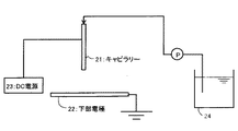
以下に、図1を参照してその方法を概説する。 The method will be outlined below with reference to FIG.
キャピラリー21と下部電極(接地電極)22との間にはDC電源23より高電圧が印加されている。貯槽24からポンプPにより原料液(ナノファイバーを形成するポリマーの溶融液又は溶解液)がキャピラリー21に送給される。キャピラリー21を出た電荷を帯びた原料液は、電界中を電極22に向かって吸い寄せられる。このとき、ポリマーが低分子であればスプレー状になって、また、高分子であれば複数に分岐した繊維が電極に向かって螺旋状に吸い寄せられ、電極22上で薄い繊維の膜(不織布状の薄膜)を形成する。このとき、電圧を上げると、形成される繊維は太くなり、逆に下げると形成される繊維が細くなるか、繊維状にならず玉状になって電極22上に付着する。このように、ナノファイバーは一般には「不織布」として製造されるが、ラボスケールでは「フィラメント」にして巻き取られる方法もある。
A high voltage is applied between the capillary 21 and the lower electrode (ground electrode) 22 from the
本発明において、多孔質支持体上にナノファイバー層を形成するには、この方法を利用して、電極22上に多孔質支持体を載置し、或いは電極22として多孔質支持体を用い、多孔質支持体上に直接ナノファイバーを堆積させれば良い。ここで、電極(又は多孔質支持体)を面方向(X−Y方向)に移動可能としておくことにより、多孔質支持体上の全面にナノファイバーを均一厚さに堆積させることができる。このようにしてナノファイバーを多孔質支持体上に堆積させた後は、必要に応じて熱圧着してナノファイバーを多孔質支持体に固定し、ナノファイバー層とすることができる。 In the present invention, in order to form the nanofiber layer on the porous support, using this method, the porous support is placed on the electrode 22, or the porous support is used as the electrode 22, The nanofibers may be deposited directly on the porous support. Here, by making the electrode (or the porous support) movable in the plane direction (XY direction), nanofibers can be deposited on the entire surface of the porous support with a uniform thickness. After the nanofibers are thus deposited on the porous support, the nanofibers can be fixed to the porous support by thermocompression bonding as necessary to form a nanofiber layer.
なお、ナノファイバーとしては、異なる材質及び/又は異なる直径のもの2種以上混合して用いても良く、また、異なる材質及び/又は異なる直径よりなるナノファイバー層を2層以上積層しても良い。 In addition, as nanofibers, two or more types of different materials and / or different diameters may be mixed and used, or two or more nanofiber layers made of different materials and / or different diameters may be laminated. .
このようにして多孔質支持体上に形成させるナノファイバー層の厚さは厚過ぎるとナノファイバー層の形成コストが高くつき、薄過ぎるとナノファイバー層を形成したことによる十分な高分子膜支持効果を得ることができないことから、0.01〜10μm程度であることが好ましい。 If the nanofiber layer formed on the porous support in this way is too thick, the cost of forming the nanofiber layer will be high, and if it is too thin, the nanofiber layer will be formed. Therefore, the thickness is preferably about 0.01 to 10 μm.
また、ナノファイバー層の密度や繊維間距離は、ナノファイバーの直径、ナノファイバーの材質や得られる分離膜の使用目的等によっても異なるが、目付として1〜100g/m2程度で見掛け上の平均孔径(平均的な繊維間距離)が0.01〜10μm程度であることが好ましい。 In addition, the density of the nanofiber layer and the distance between the fibers vary depending on the diameter of the nanofiber, the material of the nanofiber, the purpose of use of the separation membrane to be obtained, etc., but the average is about 1 to 100 g / m 2 as a basis weight. The pore diameter (average interfiber distance) is preferably about 0.01 to 10 μm.
このようにして、多孔性支持体上にナノファイバー層を形成して得られる積層支持体上に形成する高分子膜を形成する高分子としては特に制限はなく、ポリアミド、ポリイミド、ポリスルホン、ポリエーテルスルホン、酢酸セルロース、硝酸セルロース、ポリアクリロニトリル、ポリフッ化ビニリデン、ポリフッ化エチレン、ポリカーボネート、ポリビニルアルコールなどのMF膜、UF膜、RO膜等に使用される高分子の1種又は2種以上を使用することができる。 Thus, there is no restriction | limiting in particular as a polymer which forms the polymer film formed on the laminated support obtained by forming a nanofiber layer on a porous support, polyamide, polyimide, polysulfone, polyether Use one or more polymers such as sulfone, cellulose acetate, cellulose nitrate, polyacrylonitrile, polyvinylidene fluoride, polyfluorinated ethylene, polycarbonate, polyvinyl alcohol, etc. used in MF membrane, UF membrane, RO membrane, etc. be able to.
本発明においては、特に、この高分子膜は、カチオンポリマーとアニオンポリマーとが結合して形成されるポリイオンコンプレックスを層状に保持させたポリイオンコンプレックス層であることが好ましい。 In the present invention, in particular, the polymer membrane is preferably a polyion complex layer in which a polyion complex formed by combining a cationic polymer and an anionic polymer is held in a layer form.
以下に、このポリイオンコンプレックス層よりなる高分子膜について説明する。 Hereinafter, a polymer film composed of the polyion complex layer will be described.
ポリイオンコンプレックスの形成に用いるアニオンポリマー、カチオンポリマーは、正、又は負の電荷を有するものであれば良く、特に制限はないが、例えば、正の電荷を持つカチオンポリマーとしては、ポリアリルアミン、ポリスチレン4級アンモニウム(ポリビニルベンジルクロライドトリメチルアミン)、ポリエチレンイミン、ポリビニルアミン、ポリリジン、ポリジメチルアミノエチルメタクリレート、ポリジメチルアミノエチルアクリレート、ポリジアリルジメチルアンモニウム、ポリビニルピリジン、ポリビニルアミジン、或いはこれらの塩などの1種又は2種以上を使用することができる。また、負の電荷を持つアニオンポリマーとしては、ポリスチレンスルホン酸、ポリビニルスルホン酸、ポリアクリル酸、或いはこれらの塩などの1種又は2種以上を使用することができる。また、DNAなども使用することができる。また、両性ポリマーも使用することもできる。これらの素材は、強度向上のために別途界面重合させても良く、また架橋剤を併用しても良い。 The anion polymer and cation polymer used for forming the polyion complex are not particularly limited as long as they have a positive or negative charge, and examples of the cationic polymer having a positive charge include polyallylamine, polystyrene 4 1 or 2 of quaternary ammonium (polyvinylbenzyl chloride trimethylamine), polyethyleneimine, polyvinylamine, polylysine, polydimethylaminoethyl methacrylate, polydimethylaminoethyl acrylate, polydiallyldimethylammonium, polyvinylpyridine, polyvinylamidine, or salts thereof More than seeds can be used. Moreover, as an anion polymer with a negative charge, 1 type (s) or 2 or more types, such as polystyrene sulfonic acid, polyvinyl sulfonic acid, polyacrylic acid, or these salts, can be used. Moreover, DNA etc. can also be used. Amphoteric polymers can also be used. These materials may be separately subjected to interfacial polymerization for improving the strength, and a crosslinking agent may be used in combination.
本発明においては、水処理性能、強度等に優れたポリイオンコンプレックス層を形成できることから、ポリイオンコンプレックスを形成するカチオンポリマー、アニオンポリマーともに分子量50万以上の高分子量ポリマーを使用することが好ましい。ただし、分子量は過度に大きくなると、ポリイオンコンプレックス形成時のポリマー水溶液の粘性が高くなり、取り扱い性が悪くなると共に、均質なポリイオンコンプレックス層を形成し得なくなるため、2000万以下であることが好ましい。特に、カチオンポリマー及びアニオンポリマーの分子量は50万〜1000万であることが好ましい。 In the present invention, since a polyion complex layer having excellent water treatment performance and strength can be formed, it is preferable to use a high molecular weight polymer having a molecular weight of 500,000 or more for both the cationic polymer and the anionic polymer that form the polyion complex. However, if the molecular weight is excessively large, the viscosity of the aqueous polymer solution at the time of forming the polyion complex becomes high, the handleability becomes poor, and a homogeneous polyion complex layer cannot be formed. In particular, the molecular weight of the cationic polymer and the anionic polymer is preferably 500,000 to 10,000,000.
積層支持体上に、カチオンポリマーとアニオンポリマーとからなるポリイオンコンプレックス層を形成するには、これらのポリマーを積層支持体上に、スプレー、ディッピング、スピンコーティング等の方法で塗布すれば良い。ここで、塗布回数には特に制限はないが、少な過ぎると得られる高分子膜の均一性が十分でなく、多過ぎると分離膜としての透過流束の低下につながることから、5〜30回程度であることが好ましい。 In order to form a polyion complex layer composed of a cationic polymer and an anionic polymer on a laminated support, these polymers may be applied on the laminated support by a method such as spraying, dipping, spin coating or the like. Here, the number of coatings is not particularly limited, but if the amount is too small, the uniformity of the resulting polymer membrane is not sufficient, and if it is too large, the permeation flux as a separation membrane is reduced. It is preferable that it is a grade.
以下に本発明の分離膜の好適な製造方法について説明するが、本発明の分離膜の好適な製造方法は何ら以下の方法に限定されるものではない。 Although the suitable manufacturing method of the separation membrane of this invention is demonstrated below, the suitable manufacturing method of the separation membrane of this invention is not limited to the following methods at all.
本発明の分離膜は、具体的には次の(1),(2)の方法で製造される。 Specifically, the separation membrane of the present invention is produced by the following methods (1) and (2).
(1) 積層支持体に、カチオンポリマーとアニオンポリマーとを交互に吸着させることにより、この積層支持体上にカチオンポリマー層とアニオンポリマー層とが交互に積層吸着された交互積層膜を形成する。例えば、カチオンポリマー水溶液と、アニオンポリマー水溶液とを準備し、これらのポリマー水溶液に積層支持体を交互に浸漬してアニオンポリマー層とカチオンポリマー層との交互積層膜を形成する。積層支持体をカチオンポリマー水溶液とアニオンポリマー水溶液とに交互に浸漬し、各ポリマーが順次積層されると、アニオンポリマーが有する多数の負の電荷部位の一部と、隣接するカチオンポリマーが有する多数の正の電荷部位の一部とが主として静電気的に結合してポリイオンコンプレックスを形成し、ポリイオンコンプレックスが層状に積層支持体に保持された状態となり、交互積層膜からなる高分子膜が積層支持体上に形成される。 (1) By alternately adsorbing the cationic polymer and the anionic polymer on the laminated support, an alternating laminated film in which the cationic polymer layer and the anionic polymer layer are alternately adsorbed on the laminated support is formed. For example, a cationic polymer aqueous solution and an anionic polymer aqueous solution are prepared, and a laminated support is alternately dipped in these polymer aqueous solutions to form an alternately laminated film of an anionic polymer layer and a cationic polymer layer. When the laminated support is alternately dipped in an aqueous cationic polymer solution and an aqueous anionic polymer solution, and each polymer is sequentially laminated, a part of many negative charge sites of the anionic polymer and a large number of adjacent cationic polymers have. A part of the positive charge site is mainly electrostatically bonded to form a polyion complex, and the polyion complex is held in layers on the laminated support, and a polymer film composed of alternating laminated films is formed on the laminated support. Formed.
(2) 積層支持体に、カチオンポリマーとアニオンポリマーとを混合状態で吸着させることにより、積層支持体上にカチオンポリマーとアニオンポリマーとが均一に分散された均一分散膜よりなるポリイオンコンプレックス層を形成する。例えば、カチオンポリマー水溶液とアニオンポリマー水溶液とを混合した溶液に積層支持体を浸漬することによってポリイオンコンプレックス層が形成される。即ち、カチオンポリマー水溶液とアニオンポリマー水溶液とを混合した溶液中で、アニオンポリマーとカチオンポリマーとが有する電荷部位の一部が主として静電気的に結合してポリイオンコンプレックスが生成し、このポリイオンコンプレックスを含む溶液中に積層支持体を浸漬すると、この積層支持体上にポリイオンコンプレックス層よりなる高分子膜が形成される。 (2) By adsorbing the cationic polymer and anionic polymer in a mixed state on the laminated support, a polyion complex layer consisting of a uniform dispersion film in which the cationic polymer and anionic polymer are uniformly dispersed is formed on the laminated support. To do. For example, the polyion complex layer is formed by immersing the laminated support in a solution obtained by mixing a cationic polymer aqueous solution and an anionic polymer aqueous solution. That is, in a solution in which a cationic polymer aqueous solution and an anionic polymer aqueous solution are mixed, a part of the charge sites of the anionic polymer and the cationic polymer is mainly electrostatically bonded to form a polyion complex, and the solution containing this polyion complex When the laminated support is immersed therein, a polymer film made of a polyion complex layer is formed on the laminated support.
なお、上記(1),(2)の浸漬工程間では、吸着されたポリマー層の乾燥を行うことにより、ポリマー間の隙間を小さくして緻密なポリマー層を形成することができるため好ましい。 In addition, it is preferable between the dipping steps (1) and (2) above, because the adsorbed polymer layer is dried, so that a gap between the polymers can be reduced and a dense polymer layer can be formed.
以下に(1),(2)の方法についてより詳細に説明する。
(1)の方法においては、カチオンポリマー水溶液と、アニオンポリマー水溶液とを準備し、これらのポリマー水溶液に積層支持体を交互に浸漬してアニオンポリマー層とカチオンポリマー層との交互積層膜を形成するに際し、好ましくは浸漬工程の間で乾燥を行う。
Hereinafter, methods (1) and (2) will be described in more detail.
In the method (1), an aqueous cationic polymer solution and an aqueous anionic polymer solution are prepared, and an alternate laminated film of an anionic polymer layer and a cationic polymer layer is formed by alternately immersing a laminated support in these aqueous polymer solutions. In this case, drying is preferably performed between the dipping steps.
カチオンポリマー及びアニオンポリマーは、通常0.1〜100mM(モノマーユニット当たり)程度の水溶液として用いられる。 The cationic polymer and the anionic polymer are usually used as an aqueous solution of about 0.1 to 100 mM (per monomer unit).
積層支持体は、必要に応じて正、又は負の電荷を持つよう常法に従って化学処理される。積層支持体が正の電荷を持つ場合には、まず最初にアニオンポリマー水溶液に浸漬し、積層支持体が負の電荷を持つ場合には、まず最初にカチオンポリマー水溶液に浸漬して、ポリマーの吸着層を形成させる。水溶液中から引き上げた吸着層の表面は必要に応じて純水で洗浄した後、十分に乾燥させる。この乾燥方法は、積層支持体や吸着されたポリマー層に悪影響を及ぼすことのないものであれば良く、特に制限はない。例えば、乾燥炉を用いても良く、また、窒素ガス等の乾燥ガスを吹き付けて乾燥させても良い。この乾燥ガスの温度にも特に制限はなく、0〜100℃の範囲で選択可能である。 The laminated support is chemically treated according to a conventional method so as to have a positive or negative charge as required. If the laminated support has a positive charge, first immerse it in an aqueous anionic polymer solution, and if the laminated support has a negative charge, immerse it first in an aqueous cationic polymer solution to adsorb the polymer. A layer is formed. The surface of the adsorption layer pulled up from the aqueous solution is washed with pure water as necessary, and then sufficiently dried. This drying method is not particularly limited as long as it does not adversely affect the laminated support and the adsorbed polymer layer. For example, a drying furnace may be used, or drying may be performed by spraying a dry gas such as nitrogen gas. There is no restriction | limiting in particular also in the temperature of this dry gas, It can select in the range of 0-100 degreeC.
乾燥工程の終点は、例えば吹き付けた温風の温度が十分に低下した時点、或いは、吹き付けた温風の温度の低下がなくなった時点、或いは、温風を吹き付けた吸着層表面の温度が上昇し始める時点などから把握することができる。 The end point of the drying process is, for example, when the temperature of the blown hot air is sufficiently lowered, when the temperature of the blown hot air is not lowered, or when the temperature of the adsorption layer surface to which the hot air is blown increases. It can be grasped from the beginning.
このようにして吸着層の乾燥を行った後は、吸着層と逆の電荷を持つポリマー水溶液に浸漬し、同様に洗浄、及び乾燥を行う。この浸漬、洗浄、及び乾燥の工程を繰り返してカチオンポリマー層とアニオンポリマー層との交互積層膜を形成することができる。 After the adsorption layer is dried in this way, it is immersed in a polymer aqueous solution having a charge opposite to that of the adsorption layer, and similarly washed and dried. By repeating this dipping, washing, and drying steps, an alternating laminated film of a cationic polymer layer and an anionic polymer layer can be formed.
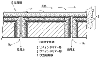
図2は、このようにして製造された分離膜5を示す模式的な断面図であり、積層支持体1の一方の面にカチオンポリマー層2とアニオンポリマー層3とが交互に積層吸着された交互積層膜(ポリイオンコンプレックス層)4が形成され、また、積層支持体1の浸漬による交互積層膜の形成工程で内部透水路1Aにもカチオンポリマー層2とアニオンポリマー層3との交互積層膜4が形成される。
FIG. 2 is a schematic cross-sectional view showing the separation membrane 5 manufactured as described above. The cationic polymer layer 2 and the anionic polymer layer 3 are alternately laminated and adsorbed on one surface of the laminated support 1. An alternating laminated film (polyion complex layer) 4 is formed, and an alternating laminated film 4 of the cationic polymer layer 2 and the anionic polymer layer 3 is also formed in the
このような分離膜5であれば、交互積層膜4側を流れる原水が交互積層膜4を通過し、その間にアニオンポリマー層3でアニオンが、カチオンポリマー層2でカチオンがそれぞれクーロン力で阻止され、また、SSが細孔で阻止され、イオン及びSSが除去された処理水が積層支持体1の透水路1Aから取り出される。
In such a separation membrane 5, raw water flowing on the alternate laminated membrane 4 side passes through the alternate laminated membrane 4, while anions are blocked by the anionic polymer layer 3 and cations are blocked by the Coulomb force in the cationic polymer layer 2. In addition, the treated water from which SS is blocked by the pores and from which ions and SS are removed is taken out from the
上述の如く、浸漬工程間で乾燥を行って製造される分離膜5であれば、各ポリマー層2,3が緻密で細孔径が小さいため、高いイオン及びSSの除去効果が得られる。 As described above, if the separation membrane 5 is manufactured by drying between the dipping steps, the polymer layers 2 and 3 are dense and the pore diameter is small, so that a high ion and SS removal effect can be obtained.
なお、このような分離膜のアニオンポリマー層及びカチオンポリマー層の厚さや積層数には特に制限はなく、分離膜の用途や要求される脱イオン性能等に応じて適宜決定される。アニオンポリマー層及びカチオンポリマー層の積層数は、多い程脱イオン性能が高くなる。一般的には、アニオンポリマー層とカチオンポリマー層との各々1層の積層膜を1レイヤーとした場合、1〜30レイヤー、好ましくは3〜20レイヤーの積層数とすることが好ましい。また、各層の厚さは、浸漬工程で用いるポリマー水溶液の濃度や浸漬時間等に応じて決定されるが、通常一層のポリマー吸着層の厚さは0.1〜20nm程度である。 In addition, there is no restriction | limiting in particular in the thickness and the number of lamination | stacking of such an anion polymer layer and a cation polymer layer of such a separation membrane, and it determines suitably according to the use of a separation membrane, the required deionization performance, etc. The greater the number of laminated anionic polymer layers and cationic polymer layers, the higher the deionization performance. In general, when one laminated film of an anionic polymer layer and a cationic polymer layer is used as one layer, the number of laminated layers is preferably 1 to 30 layers, preferably 3 to 20 layers. Moreover, although the thickness of each layer is determined according to the density | concentration of the polymer aqueous solution used at an immersion process, immersion time, etc., the thickness of one polymer adsorption layer is about 0.1-20 nm normally.
次に、前記(2)の方法でカチオンポリマーとアニオンポリマーとの均一分散膜よりなるポリイオンコンプレックス層を有する分離膜を製造する方法について説明する。 Next, a method for producing a separation membrane having a polyion complex layer comprising a uniform dispersion membrane of a cationic polymer and an anionic polymer by the method (2) will be described.
上記(1)の方法で、カチオンポリマー層とアニオンポリマー層とを交互に積層吸着してポリイオンコンプレックス層を形成する場合は、積層吸着の際にポリイオンコンプレックスが生成して、両ポリマーが結合し、ポリイオンコンプレックス層を形成するが、(2)の方法では、予めポリイオンコンプレックスを生成させてから積層支持体にポリイオンコンプレックス層を形成させる。この場合には、(1)の方法と同様にして調製されるカチオンポリマー水溶液とアニオンポリマー水溶液とを混合して混合溶液を準備する。この混合溶液中のカチオンポリマーの濃度は0.01〜10mM(モノマーユニット当たり)程度、アニオンポリマーの濃度は0.01〜10mM(モノマーユニット当たり)程度であることが好ましい。混合状態でアニオンポリマーとカチオンポリマーとがそれぞれ有する電荷部位の一部が主として静電気的に結合してポリイオンコンプレックスを生成する。ポリイオンコンプレックスが生成した混合溶液に積層支持体を浸漬すると積層支持体の空隙に混合溶液が浸透し、ポリイオンコンプレックスの未反応のままの電荷部位が支持材の電荷部位に吸着し、また、別の未反応の電荷部位が他のポリイオンコンプレックスの未反応部位と吸着し、これが繰り返されて積層支持体にポリイオンコンプレックス層が保持され、形成されていく。 When the polyion complex layer is formed by alternately laminating and adsorbing the cationic polymer layer and the anionic polymer layer by the method of (1) above, the polyion complex is generated during the laminating adsorption, and both polymers are combined, A polyion complex layer is formed. In the method (2), after a polyion complex is generated in advance, the polyion complex layer is formed on the laminated support. In this case, a cationic polymer aqueous solution and an anionic polymer aqueous solution prepared in the same manner as in the method (1) are mixed to prepare a mixed solution. The concentration of the cationic polymer in the mixed solution is preferably about 0.01 to 10 mM (per monomer unit), and the concentration of the anionic polymer is preferably about 0.01 to 10 mM (per monomer unit). In the mixed state, some of the charge sites of the anionic polymer and the cationic polymer are mainly electrostatically bonded to form a polyion complex. When the laminated support is immersed in the mixed solution produced by the polyion complex, the mixed solution penetrates into the voids of the laminated support, and the unreacted charge sites of the polyion complex are adsorbed on the charge sites of the support material. Unreacted charge sites are adsorbed with unreacted sites of other polyion complexes, and this is repeated to hold and form the polyion complex layer on the laminated support.
(2)の方法では、カチオンポリマーとアニオンポリマーとの混合水溶液中に積層支持体を浸漬して、ポリマーの吸着層を形成させる。水溶液中から引き上げた後、吸着層の表面は必要に応じて純水で洗浄した後、十分に乾燥させる。そして、吸着層の乾燥を行った後、積層支持体を再び混合水溶液に浸漬し、同様に洗浄、及び乾燥を行う。この浸漬、洗浄、及び乾燥の工程を繰り返す。 In the method (2), the laminated support is immersed in a mixed aqueous solution of a cationic polymer and an anionic polymer to form a polymer adsorption layer. After pulling up from the aqueous solution, the surface of the adsorption layer is washed with pure water as necessary, and then sufficiently dried. And after drying an adsorption layer, a laminated support body is again immersed in mixed aqueous solution, and washing and drying are performed similarly. This dipping, washing and drying process is repeated.
このようにして形成されたポリイオンコンプレックス層を有する分離膜では、図2に示す分離膜と同様、積層支持体表面だけではなく、内部透水路にまでポリイオンコンプレックス層が形成されたものとなるが、カチオンポリマーとアニオンポリマーとはポリイオンコンプレックス層全体にほぼ均一に分散された状態で存在する。このカチオンポリマーとアニオンポリマーとが均一に分散された均一分散膜を積層支持体上に有する分離膜に原水を通水すると、均一分散膜において水中のカチオン、アニオンはクーロン力で通過が阻止され、またSSが細孔で阻止され、イオン及びSSが除去された処理水が膜を透過し、積層支持体の内部透水路から取り出される。 In the separation membrane having the polyion complex layer formed as described above, the polyion complex layer is formed not only on the surface of the laminated support but also on the internal water passage, as in the separation membrane shown in FIG. The cationic polymer and the anionic polymer exist in a substantially uniformly dispersed state throughout the polyion complex layer. When raw water is passed through a separation membrane having a uniform dispersion membrane on which the cation polymer and anion polymer are uniformly dispersed on the laminated support, the cations and anions in the water are blocked from passing by the Coulomb force in the uniform dispersion membrane, Further, SS is blocked by the pores, and the treated water from which ions and SS have been removed passes through the membrane and is taken out from the internal water passage of the laminated support.
このような分離膜においても、ポリイオンコンプレックス層の厚さには特に制限はなく、用途や要求される脱イオン性能等に応じて適宜決定される。ポリイオンコンプレックス層は厚い程脱イオン性能が高くなるが、一般的には、前述の浸漬・乾燥工程を10〜100回行って、積層数10〜100層、総厚さ100〜1000nm程度のポリイオンコンプレックス層を形成することが好ましい。なお、この(2)の方法においても1回で形成されるポリイオンコンプレックス層の厚さは、浸漬工程で用いる混合ポリマー水溶液の濃度や浸漬時間等に応じて決定される。 Also in such a separation membrane, the thickness of the polyion complex layer is not particularly limited, and is appropriately determined according to the application, required deionization performance, and the like. The thicker the polyion complex layer, the higher the deionization performance. In general, the polyion complex having about 10 to 100 layers and a total thickness of about 100 to 1000 nm is obtained by performing the above-described immersion / drying process 10 to 100 times. It is preferable to form a layer. In the method (2), the thickness of the polyion complex layer formed at one time is determined according to the concentration of the mixed polymer aqueous solution used in the dipping step, the dipping time, and the like.
本発明の分離膜は、水処理装置に用いて、水中のイオンやSSの除去に有効に使用されるが、水処理装置に限らず、本発明の分離膜は、ガスの除塵処理、清浄化処理にも有効であり、更に、新しい非線形光学材料としての用途も期待される。 The separation membrane of the present invention is effectively used for removal of ions and SS in water by using it in a water treatment device, but the separation membrane of the present invention is not limited to a water treatment device, and the dust removal treatment and purification of gas. It is also effective for processing and is expected to be used as a new nonlinear optical material.
次に、このような本発明の分離膜を用いた本発明の水処理装置について図3を参照して説明する。 Next, the water treatment apparatus of the present invention using such a separation membrane of the present invention will be described with reference to FIG.
図3は本発明の水処理装置の実施の形態を示す概略的な断面図である。 FIG. 3 is a schematic sectional view showing an embodiment of the water treatment apparatus of the present invention.
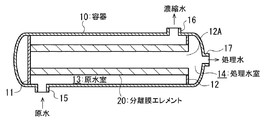
この水処理装置では、容器(ベッセル)10内の両端部に仕切板11,12が設けられ、原水室13と処理水室14とが形成されている。原水室13には、仕切板11,12間に中空管状の分離膜エレメント20が懸架されている。一方の仕切板12には、開口12Aが設けられ、分離膜エレメント20の一端側は、この開口12A部に取り付けられ、分離膜エレメント20の中空管内が処理水室14に連通している。15は原水の導入口、16は濃縮水の取出口、17は処理水の取出口である。
In this water treatment apparatus,
導入口15からこの水処理装置に導入された原水は、例えば、図2に示す如く、分離膜5の交互積層膜(ポリイオンコンプレックス層)4面をクロスフロー方式で流れ、この交互積層膜(ポリイオンコンプレックス層)4を積層方向に通過し、その間にイオン及びSSが除去される。分離膜を通過した処理水は、分離膜エレメント20の中空部から処理水室14を経て処理水取出口17から取り出される。一方、膜で排除されたイオンやSSが濃縮された濃縮水は濃縮水取出口16から取り出される。この濃縮水は、必要に応じて一部を原水導入側に戻して循環処理し、残部を系外へ取り出すようにしても良い。
For example, as shown in FIG. 2, the raw water introduced into the water treatment apparatus from the
図3には、中空管状の分離膜エレメント20を設けた水処理装置を示したが、本発明の水処理装置の分離膜の型式には特に制限はなく、中空糸膜であっても平膜であっても良い。単位体積当たりの膜の表面積を大きく確保する点では中空糸膜が好ましい。いずれの形式の膜も容器内に収容し、原水を加圧して容器に供給する加圧給水型とすることが好ましいが、開放系の水中に分離膜を浸漬し、処理水側を減圧して処理水を得る浸漬型であっても良い。このときの給水圧力や減圧の程度についても特に制限はなく、膜を通して所望の処理水量が得られるように適宜決定される。また、平膜は、プレートアンドフレーム型で使用しても、スパイラル型で使用しても良い。これらの膜形式、装置形式は、MF膜装置、UF膜装置、RO膜装置におけるものと同様であり、それらの既知の技術を転用して本発明の水処理装置を組み立てることができる。 FIG. 3 shows a water treatment apparatus provided with a hollow tubular separation membrane element 20, but there is no particular limitation on the type of the separation membrane of the water treatment apparatus of the present invention, and even a hollow fiber membrane is a flat membrane. It may be. A hollow fiber membrane is preferable in terms of ensuring a large surface area of the membrane per unit volume. Either type of membrane is housed in a container, preferably a pressurized water supply type that pressurizes raw water and supplies it to the container, but the separation membrane is immersed in open water and the treated water side is depressurized. An immersion type for obtaining treated water may be used. There is no restriction | limiting in particular also about the grade of the feed water pressure and pressure reduction at this time, and it determines suitably so that a desired amount of treated water may be obtained through a film | membrane. Further, the flat membrane may be used in a plate and frame type or in a spiral type. These membrane types and device types are the same as those in the MF membrane device, UF membrane device, and RO membrane device, and the water treatment device of the present invention can be assembled by diverting those known techniques.
分離膜への通水方式についても特に制限はなく、クロスフロー(平行流濾過)方式でもデッドエンド方式でも、いずれも適用可能であるが、デッドエンド方式では膜が目詰まりする可能性があるため、クロスフロー方式を採用することが好ましい。 There is no particular restriction on the water flow method to the separation membrane, and both the cross flow (parallel flow filtration) method and the dead end method can be applied. However, the dead end method may clog the membrane. It is preferable to adopt a cross flow method.
以下に実施例及び比較例を挙げて本発明をより具体的に説明する。 Hereinafter, the present invention will be described more specifically with reference to Examples and Comparative Examples.
実施例1
図1に示す方法で、多孔性支持体上にナノファイバー層を形成した。
Example 1
A nanofiber layer was formed on the porous support by the method shown in FIG.
ナノファイバー原料としては、10重量%のポリ塩化ビニル−テトラヒドロフラン溶液を用い、印加電圧20kV/cm、電極間距離15cm、原料の押出速度50μL/minとした。電極側の試料台はX−Y軸方向(面方向)に移動可能であり、均一なナノファイバー層を形成することができる。 As the nanofiber raw material, a 10% by weight polyvinyl chloride-tetrahydrofuran solution was used, the applied voltage was 20 kV / cm, the distance between the electrodes was 15 cm, and the extrusion rate of the raw material was 50 μL / min. The electrode-side sample stage is movable in the XY axis direction (plane direction), and a uniform nanofiber layer can be formed.
多孔性支持体としては、ポリエステル不織布(目付150g/m2、電子顕微鏡観察において平均孔径は約20μmであることが確認された。)を用い、この上にナノファイバーを堆積させた後、200℃で10秒間熱圧着してナノファイバー層を固定した。 As the porous support, a polyester non-woven fabric (weight per unit area: 150 g / m 2 , average pore diameter was confirmed to be about 20 μm by observation with an electron microscope), nanofibers were deposited thereon, and then 200 ° C. The nanofiber layer was fixed by thermocompression bonding for 10 seconds.
このようにして形成された積層支持体のナノファイバーの平均繊維径は100nm、ナノファイバー層の厚さは0.1μm、ナノファイバー層の目付は20g/m2で、その平均細孔径は、電子顕微鏡観察において0.5μmであった。 The average fiber diameter of the nanofibers of the laminated support thus formed is 100 nm, the thickness of the nanofiber layer is 0.1 μm, the basis weight of the nanofiber layer is 20 g / m 2 , and the average pore diameter is It was 0.5 μm in microscopic observation.
別に、濃度2g/Lのポリ−4−ビニルピリジン(分子量30万)水溶液と、濃度2g/Lのポリスチレンスルホン酸(分子量100万)水溶液とを調製した。 Separately, an aqueous solution of poly-4-vinylpyridine (molecular weight 300,000) having a concentration of 2 g / L and an aqueous solution of polystyrene sulfonic acid (molecular weight 1 million) having a concentration of 2 g / L were prepared.
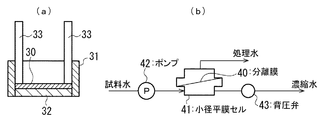
図4(a)に示す膜固定容器31に、ナノファイバー層形成不織布30の片面(ナノファイバー層側)にのみポリマーが吸着されるようにナノファイバー層形成不織布30を固定した。図4(a)中、32は支持板、33は支持棒である。この状態でまず、ポリ−4−ビニルピリジン水溶液を容器31に投入して1分間静置した後、この水溶液を捨て、その後膜面を純水で洗浄して未反応高分子を除去し、更にドライヤーで5分間乾燥(65℃)させた。その後、ポリスチレンスルホン酸水溶液を容器31に投入して1分間静置した後、この水溶液を捨て、その後膜面を純水で洗浄して未反応高分子を除去し、更にドライヤーで5分間乾燥(65℃)させた。このようにしてポリ−4−ビニルピリジンの吸着層とポリスチレンスルホン酸の吸着層との積層膜を形成する工程を1レイヤーとして、これを繰り返し、レイヤー数5の交互積層膜を積層支持体上に形成して分離膜を製造した。
The nanofiber layer-formed
このようにして、交互積層膜よりなる高分子膜を形成した状態においては、電子顕微鏡観察の結果、繊維隙間は観察されず、分離膜が形成されていた。 Thus, in the state in which the polymer film composed of the alternately laminated films was formed, the fiber gap was not observed as a result of the electron microscope observation, and a separation membrane was formed.
この分離膜40を図4(b)に示す平膜試験装置の小径平膜セル41に取り付け、その性能を評価する実験を行った。図4(b)において、42はポンプ、43は背圧弁である。試料水には1g/LのNaCl水溶液、MgSO4水溶液又はデキストラン(分子量7万)水溶液を用い、流量1.4mL/minで平膜セル41に導入して膜分離処理した。セル41にかかる圧力は背圧弁43で調整した。膜によって圧力は異なるが、圧力と透過水量(フラックス)は比例関係にあるので、得られた透過水量はすべて1.0MPaの場合に換算して表記した(換算フラックス(m/day)=得られたフラックス×(1.0MPa/操作圧力1MPa))。連続通水後の処理水(透過水)の溶質(NaCl、MgSO4又はデキストラン)濃度を測定し、各溶質の除去率((試料水の溶質濃度−処理水の溶質濃度)÷試料水の溶質濃度×100)(%)を算出した。得られた結果を表1に示す。 This separation membrane 40 was attached to a small-diameter flat membrane cell 41 of the flat membrane test apparatus shown in FIG. 4B, and an experiment was conducted to evaluate its performance. In FIG.4 (b), 42 is a pump and 43 is a back pressure valve. As sample water, a 1 g / L NaCl aqueous solution, a MgSO 4 aqueous solution or a dextran (molecular weight 70,000) aqueous solution was introduced into the flat membrane cell 41 at a flow rate of 1.4 mL / min for membrane separation treatment. The pressure applied to the cell 41 was adjusted by the back pressure valve 43. Although the pressure varies depending on the membrane, since the pressure and the amount of permeated water (flux) are in a proportional relationship, all the amounts of permeated water obtained were converted to 1.0 MPa (converted flux (m / day) = obtained). Flux × (1.0 MPa / operating pressure 1 MPa)). Measure the concentration of solute (NaCl, MgSO 4 or dextran) in treated water (permeated water) after continuous water flow, and the removal rate of each solute ((solute concentration of sample water-solute concentration of treated water) ÷ solute of sample water (Concentration × 100) (%) was calculated. The obtained results are shown in Table 1.
比較例1
実施例1で用いた不織布をそのまま分離膜として用い、各溶質の除去率と換算フラックスを調べ、結果を表1に示した。
Comparative Example 1
Using the nonwoven fabric used in Example 1 as a separation membrane as it was, the removal rate of each solute and the converted flux were examined, and the results are shown in Table 1.
比較例2
実施例1と同様にしてナノファイバー層を形成した不織布を、交互積層膜を形成せずに分離膜として用い、実施例1と同様にして各溶質の除去率と換算フラックスを調べ、結果を表1に示した。
Comparative Example 2
The nonwoven fabric in which the nanofiber layer was formed in the same manner as in Example 1 was used as a separation membrane without forming an alternately laminated film, and the removal rate of each solute and the converted flux were examined in the same manner as in Example 1, and the results were shown. It was shown in 1.
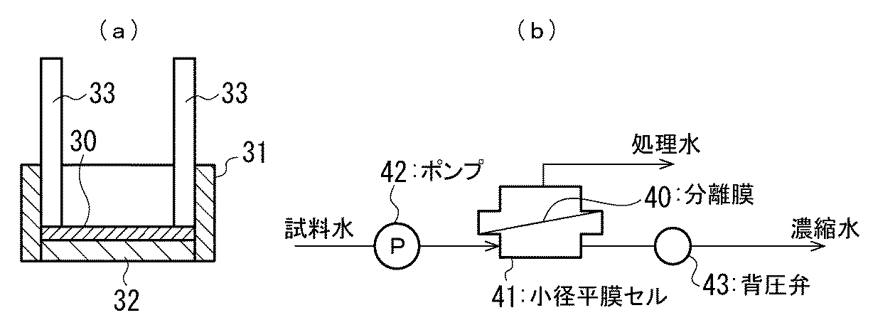
表1より明らかなように、比較例1の分離膜では、除去性能を全く得ることができず、比較例2の分離膜ではイオン性の物質については十分な除去性能を得ることができなかったが、ナノファイバー層形成不織布に交互積層膜を形成した実施例1では、いずれの溶質についても良好な除去性能を得ることができた。 As is clear from Table 1, the separation membrane of Comparative Example 1 could not obtain any removal performance, and the separation membrane of Comparative Example 2 could not obtain sufficient removal performance for ionic substances. However, in Example 1 in which the alternating laminated film was formed on the nanofiber layer-formed nonwoven fabric, good removal performance could be obtained for any solute.
1 積層支持体
2 カチオンポリマー層
3 アニオンポリマー層
4 交互積層膜(高分子膜)
5 分離膜
10 容器
13 原水室
14 処理水室
20 分離膜エレメント
21 キャピラリー
22 電極
23 DC電源
30 ナノファイバー層形成不織布
31 膜固定容器
40 分離膜
41 小径平膜セル
DESCRIPTION OF SYMBOLS 1 Laminated support 2 Cationic polymer layer 3 Anion polymer layer 4 Alternating laminated film (polymer film)
5 Separation membrane 10 Container 13 Raw water chamber 14 Treated water chamber 20 Separation membrane element 21 Capillary 22
Claims (3)
Priority Applications (1)
| Application Number | Priority Date | Filing Date | Title |
|---|---|---|---|
| JP2005092009A JP4736498B2 (en) | 2005-03-28 | 2005-03-28 | Separation membrane and water treatment device |
Applications Claiming Priority (1)
| Application Number | Priority Date | Filing Date | Title |
|---|---|---|---|
| JP2005092009A JP4736498B2 (en) | 2005-03-28 | 2005-03-28 | Separation membrane and water treatment device |
Publications (2)
| Publication Number | Publication Date |
|---|---|
| JP2006272067A JP2006272067A (en) | 2006-10-12 |
| JP4736498B2 true JP4736498B2 (en) | 2011-07-27 |
Family
ID=37207327
Family Applications (1)
| Application Number | Title | Priority Date | Filing Date |
|---|---|---|---|
| JP2005092009A Expired - Fee Related JP4736498B2 (en) | 2005-03-28 | 2005-03-28 | Separation membrane and water treatment device |
Country Status (1)
| Country | Link |
|---|---|
| JP (1) | JP4736498B2 (en) |
Families Citing this family (10)
| Publication number | Priority date | Publication date | Assignee | Title |
|---|---|---|---|---|
| US8038013B2 (en) * | 2007-03-06 | 2011-10-18 | E.I. Du Pont De Nemours And Company | Liquid filtration media |
| US7993523B2 (en) | 2007-03-06 | 2011-08-09 | E. I. Du Pont De Nemours And Company | Liquid filtration media |
| JP2009183879A (en) * | 2008-02-07 | 2009-08-20 | Japan Vilene Co Ltd | Separation membrane substrate sheet, method for producing the same, and separation membrane laminate sheet |
| US7993524B2 (en) * | 2008-06-30 | 2011-08-09 | Nanoasis Technologies, Inc. | Membranes with embedded nanotubes for selective permeability |
| JP5456394B2 (en) * | 2009-07-09 | 2014-03-26 | 国立大学法人神戸大学 | Composite semipermeable membrane |
| US9346020B2 (en) | 2009-12-28 | 2016-05-24 | Kuraray Co., Ltd. | Multilayered charge-mosaic membrane and manufacturing method therefor |
| JP2012210593A (en) * | 2011-03-31 | 2012-11-01 | Kurita Water Ind Ltd | Ultrapure water producing system and ultrapure water producing method |
| JP2014184378A (en) * | 2013-03-22 | 2014-10-02 | Daicel Corp | Cationic polymer and anionic polymer composite semipermeable membrane |
| JP6484748B1 (en) | 2018-09-20 | 2019-03-13 | 日東電工株式会社 | Separation membrane |
| JP7027364B2 (en) * | 2019-03-12 | 2022-03-01 | 日東電工株式会社 | Sulfate ion removal system and method |
Family Cites Families (3)
| Publication number | Priority date | Publication date | Assignee | Title |
|---|---|---|---|---|
| JPS61153102A (en) * | 1984-12-26 | 1986-07-11 | Wako Pure Chem Ind Ltd | Novel separation of organic acid from saccharide |
| JPS63278517A (en) * | 1987-05-12 | 1988-11-16 | Yuasa Battery Co Ltd | Filter |
| JPH11114383A (en) * | 1997-10-15 | 1999-04-27 | Chisso Corp | Cylindrical filter cartridge |
-
2005
- 2005-03-28 JP JP2005092009A patent/JP4736498B2/en not_active Expired - Fee Related
Also Published As
| Publication number | Publication date |
|---|---|
| JP2006272067A (en) | 2006-10-12 |
Similar Documents
| Publication | Publication Date | Title |
|---|---|---|
| KR101926832B1 (en) | Separation membrane, method for preparing thereof, unit for purification, and their use | |
| JP6320537B2 (en) | Forward osmosis membrane and forward osmosis treatment system | |
| KR101907106B1 (en) | Semi-permeable film and membrane including nanoporous material, and method of manufacturing the same | |
| Zhu et al. | Fabrication of composite membrane with adsorption property and its application to the removal of endocrine disrupting compounds during filtration process | |
| JP5062630B2 (en) | Composite fiber body, method for producing the same, filter, and fluid filtration method | |
| CN105642129A (en) | A positively charged nanofiltration membrane based on tertiary amine amphiphilic copolymer and its preparation method | |
| CN101861201A (en) | high performance film | |
| JP6694326B2 (en) | Composite membrane | |
| EP2745919A1 (en) | Composite semipermeable membrane | |
| CN101472671A (en) | Polymer separation film and preparation method thereof | |
| Liu et al. | Ultrafast loose nanofiltration membrane intercalated by in-situ grown nanoparticles for dye purification and reuse | |
| JPWO2014192883A1 (en) | Composite semipermeable membrane | |
| KR101572660B1 (en) | Reverse osmosis membrane with nanofiber-web layer and method for manufacturing thereof | |
| Li et al. | Tailoring the polyamide active layer of thin-film composite forward osmosis membranes with combined cosolvents during interfacial polymerization | |
| JP4736498B2 (en) | Separation membrane and water treatment device | |
| JP2016155078A (en) | Forward osmosis processing system | |
| CN111644080B (en) | Highly hydrophilic nanofiber coating-based nanofiltration membrane and preparation method thereof | |
| JP2010158606A (en) | Filter, method of manufacturing the same, and method of treating fluid | |
| JP2006187731A (en) | Separation membrane and water treatment device | |
| US20160369076A1 (en) | Super hydrophobic multiscale porous polymer films | |
| WO2018063122A2 (en) | Forward osmosis membrane obtained by using sulfonated polysulfone (spsf) polymer and production method thereof | |
| US20160137802A1 (en) | Multiscale porous polymer films | |
| Zhou et al. | High efficient thin-film composite membrane: Ultrathin hydrophilic polyamide film on macroporous superhydrophobic polytetrafluoroethylene substrate | |
| KR20150079213A (en) | Reverse-osmosis membrane having excellent pressure-resistant and method for manufacturing thereof | |
| KR20160121987A (en) | Monomer Limited Interfacial Polymerization Method and Separation Membrane Prepared by the Same |
Legal Events
| Date | Code | Title | Description |
|---|---|---|---|
| A621 | Written request for application examination |
Free format text: JAPANESE INTERMEDIATE CODE: A621 Effective date: 20080303 |
|
| A977 | Report on retrieval |
Free format text: JAPANESE INTERMEDIATE CODE: A971007 Effective date: 20090421 |
|
| A131 | Notification of reasons for refusal |
Free format text: JAPANESE INTERMEDIATE CODE: A131 Effective date: 20110118 |
|
| A521 | Request for written amendment filed |
Free format text: JAPANESE INTERMEDIATE CODE: A523 Effective date: 20110308 |
|
| A01 | Written decision to grant a patent or to grant a registration (utility model) |
Free format text: JAPANESE INTERMEDIATE CODE: A01 Effective date: 20110405 |
|
| A61 | First payment of annual fees (during grant procedure) |
Free format text: JAPANESE INTERMEDIATE CODE: A61 Effective date: 20110418 |
|
| R150 | Certificate of patent or registration of utility model |
Free format text: JAPANESE INTERMEDIATE CODE: R150 |
|
| FPAY | Renewal fee payment (event date is renewal date of database) |
Free format text: PAYMENT UNTIL: 20140513 Year of fee payment: 3 |
|
| LAPS | Cancellation because of no payment of annual fees |