JP2005281131A - System and method for co-production of hydrogen and electrical energy - Google Patents
System and method for co-production of hydrogen and electrical energy Download PDFInfo
- Publication number
- JP2005281131A JP2005281131A JP2005090941A JP2005090941A JP2005281131A JP 2005281131 A JP2005281131 A JP 2005281131A JP 2005090941 A JP2005090941 A JP 2005090941A JP 2005090941 A JP2005090941 A JP 2005090941A JP 2005281131 A JP2005281131 A JP 2005281131A
- Authority
- JP
- Japan
- Prior art keywords
- reformer
- combustor
- hydrogen
- produce
- fuel
- Prior art date
- Legal status (The legal status is an assumption and is not a legal conclusion. Google has not performed a legal analysis and makes no representation as to the accuracy of the status listed.)
- Pending
Links
Images


Classifications
-
- C—CHEMISTRY; METALLURGY
- C01—INORGANIC CHEMISTRY
- C01B—NON-METALLIC ELEMENTS; COMPOUNDS THEREOF; METALLOIDS OR COMPOUNDS THEREOF NOT COVERED BY SUBCLASS C01C
- C01B3/00—Hydrogen; Gaseous mixtures containing hydrogen; Separation of hydrogen from mixtures containing it; Purification of hydrogen
- C01B3/02—Production of hydrogen or of gaseous mixtures containing a substantial proportion of hydrogen
- C01B3/32—Production of hydrogen or of gaseous mixtures containing a substantial proportion of hydrogen by reaction of gaseous or liquid organic compounds with gasifying agents, e.g. water, carbon dioxide, air
- C01B3/34—Production of hydrogen or of gaseous mixtures containing a substantial proportion of hydrogen by reaction of gaseous or liquid organic compounds with gasifying agents, e.g. water, carbon dioxide, air by reaction of hydrocarbons with gasifying agents
-
- C—CHEMISTRY; METALLURGY
- C01—INORGANIC CHEMISTRY
- C01B—NON-METALLIC ELEMENTS; COMPOUNDS THEREOF; METALLOIDS OR COMPOUNDS THEREOF NOT COVERED BY SUBCLASS C01C
- C01B3/00—Hydrogen; Gaseous mixtures containing hydrogen; Separation of hydrogen from mixtures containing it; Purification of hydrogen
- C01B3/50—Separation of hydrogen or hydrogen containing gases from gaseous mixtures, e.g. purification
-
- C—CHEMISTRY; METALLURGY
- C01—INORGANIC CHEMISTRY
- C01B—NON-METALLIC ELEMENTS; COMPOUNDS THEREOF; METALLOIDS OR COMPOUNDS THEREOF NOT COVERED BY SUBCLASS C01C
- C01B2203/00—Integrated processes for the production of hydrogen or synthesis gas
- C01B2203/02—Processes for making hydrogen or synthesis gas
- C01B2203/0205—Processes for making hydrogen or synthesis gas containing a reforming step
- C01B2203/0227—Processes for making hydrogen or synthesis gas containing a reforming step containing a catalytic reforming step
- C01B2203/0233—Processes for making hydrogen or synthesis gas containing a reforming step containing a catalytic reforming step the reforming step being a steam reforming step
-
- C—CHEMISTRY; METALLURGY
- C01—INORGANIC CHEMISTRY
- C01B—NON-METALLIC ELEMENTS; COMPOUNDS THEREOF; METALLOIDS OR COMPOUNDS THEREOF NOT COVERED BY SUBCLASS C01C
- C01B2203/00—Integrated processes for the production of hydrogen or synthesis gas
- C01B2203/02—Processes for making hydrogen or synthesis gas
- C01B2203/0283—Processes for making hydrogen or synthesis gas containing a CO-shift step, i.e. a water gas shift step
-
- C—CHEMISTRY; METALLURGY
- C01—INORGANIC CHEMISTRY
- C01B—NON-METALLIC ELEMENTS; COMPOUNDS THEREOF; METALLOIDS OR COMPOUNDS THEREOF NOT COVERED BY SUBCLASS C01C
- C01B2203/00—Integrated processes for the production of hydrogen or synthesis gas
- C01B2203/04—Integrated processes for the production of hydrogen or synthesis gas containing a purification step for the hydrogen or the synthesis gas
- C01B2203/0405—Purification by membrane separation
-
- C—CHEMISTRY; METALLURGY
- C01—INORGANIC CHEMISTRY
- C01B—NON-METALLIC ELEMENTS; COMPOUNDS THEREOF; METALLOIDS OR COMPOUNDS THEREOF NOT COVERED BY SUBCLASS C01C
- C01B2203/00—Integrated processes for the production of hydrogen or synthesis gas
- C01B2203/04—Integrated processes for the production of hydrogen or synthesis gas containing a purification step for the hydrogen or the synthesis gas
- C01B2203/0415—Purification by absorption in liquids
-
- C—CHEMISTRY; METALLURGY
- C01—INORGANIC CHEMISTRY
- C01B—NON-METALLIC ELEMENTS; COMPOUNDS THEREOF; METALLOIDS OR COMPOUNDS THEREOF NOT COVERED BY SUBCLASS C01C
- C01B2203/00—Integrated processes for the production of hydrogen or synthesis gas
- C01B2203/04—Integrated processes for the production of hydrogen or synthesis gas containing a purification step for the hydrogen or the synthesis gas
- C01B2203/042—Purification by adsorption on solids
- C01B2203/043—Regenerative adsorption process in two or more beds, one for adsorption, the other for regeneration
-
- C—CHEMISTRY; METALLURGY
- C01—INORGANIC CHEMISTRY
- C01B—NON-METALLIC ELEMENTS; COMPOUNDS THEREOF; METALLOIDS OR COMPOUNDS THEREOF NOT COVERED BY SUBCLASS C01C
- C01B2203/00—Integrated processes for the production of hydrogen or synthesis gas
- C01B2203/04—Integrated processes for the production of hydrogen or synthesis gas containing a purification step for the hydrogen or the synthesis gas
- C01B2203/0465—Composition of the impurity
- C01B2203/047—Composition of the impurity the impurity being carbon monoxide
-
- C—CHEMISTRY; METALLURGY
- C01—INORGANIC CHEMISTRY
- C01B—NON-METALLIC ELEMENTS; COMPOUNDS THEREOF; METALLOIDS OR COMPOUNDS THEREOF NOT COVERED BY SUBCLASS C01C
- C01B2203/00—Integrated processes for the production of hydrogen or synthesis gas
- C01B2203/04—Integrated processes for the production of hydrogen or synthesis gas containing a purification step for the hydrogen or the synthesis gas
- C01B2203/0465—Composition of the impurity
- C01B2203/0475—Composition of the impurity the impurity being carbon dioxide
-
- C—CHEMISTRY; METALLURGY
- C01—INORGANIC CHEMISTRY
- C01B—NON-METALLIC ELEMENTS; COMPOUNDS THEREOF; METALLOIDS OR COMPOUNDS THEREOF NOT COVERED BY SUBCLASS C01C
- C01B2203/00—Integrated processes for the production of hydrogen or synthesis gas
- C01B2203/08—Methods of heating or cooling
- C01B2203/0805—Methods of heating the process for making hydrogen or synthesis gas
- C01B2203/0811—Methods of heating the process for making hydrogen or synthesis gas by combustion of fuel
- C01B2203/0822—Methods of heating the process for making hydrogen or synthesis gas by combustion of fuel the fuel containing hydrogen
-
- C—CHEMISTRY; METALLURGY
- C01—INORGANIC CHEMISTRY
- C01B—NON-METALLIC ELEMENTS; COMPOUNDS THEREOF; METALLOIDS OR COMPOUNDS THEREOF NOT COVERED BY SUBCLASS C01C
- C01B2203/00—Integrated processes for the production of hydrogen or synthesis gas
- C01B2203/08—Methods of heating or cooling
- C01B2203/0805—Methods of heating the process for making hydrogen or synthesis gas
- C01B2203/0811—Methods of heating the process for making hydrogen or synthesis gas by combustion of fuel
- C01B2203/0827—Methods of heating the process for making hydrogen or synthesis gas by combustion of fuel at least part of the fuel being a recycle stream
-
- C—CHEMISTRY; METALLURGY
- C01—INORGANIC CHEMISTRY
- C01B—NON-METALLIC ELEMENTS; COMPOUNDS THEREOF; METALLOIDS OR COMPOUNDS THEREOF NOT COVERED BY SUBCLASS C01C
- C01B2203/00—Integrated processes for the production of hydrogen or synthesis gas
- C01B2203/12—Feeding the process for making hydrogen or synthesis gas
- C01B2203/1288—Evaporation of one or more of the different feed components
- C01B2203/1294—Evaporation by heat exchange with hot process stream
-
- C—CHEMISTRY; METALLURGY
- C01—INORGANIC CHEMISTRY
- C01B—NON-METALLIC ELEMENTS; COMPOUNDS THEREOF; METALLOIDS OR COMPOUNDS THEREOF NOT COVERED BY SUBCLASS C01C
- C01B2203/00—Integrated processes for the production of hydrogen or synthesis gas
- C01B2203/14—Details of the flowsheet
- C01B2203/148—Details of the flowsheet involving a recycle stream to the feed of the process for making hydrogen or synthesis gas
-
- C—CHEMISTRY; METALLURGY
- C01—INORGANIC CHEMISTRY
- C01B—NON-METALLIC ELEMENTS; COMPOUNDS THEREOF; METALLOIDS OR COMPOUNDS THEREOF NOT COVERED BY SUBCLASS C01C
- C01B2203/00—Integrated processes for the production of hydrogen or synthesis gas
- C01B2203/80—Aspect of integrated processes for the production of hydrogen or synthesis gas not covered by groups C01B2203/02 - C01B2203/1695
- C01B2203/86—Carbon dioxide sequestration
-
- Y—GENERAL TAGGING OF NEW TECHNOLOGICAL DEVELOPMENTS; GENERAL TAGGING OF CROSS-SECTIONAL TECHNOLOGIES SPANNING OVER SEVERAL SECTIONS OF THE IPC; TECHNICAL SUBJECTS COVERED BY FORMER USPC CROSS-REFERENCE ART COLLECTIONS [XRACs] AND DIGESTS
- Y02—TECHNOLOGIES OR APPLICATIONS FOR MITIGATION OR ADAPTATION AGAINST CLIMATE CHANGE
- Y02E—REDUCTION OF GREENHOUSE GAS [GHG] EMISSIONS, RELATED TO ENERGY GENERATION, TRANSMISSION OR DISTRIBUTION
- Y02E20/00—Combustion technologies with mitigation potential
- Y02E20/16—Combined cycle power plant [CCPP], or combined cycle gas turbine [CCGT]
-
- Y—GENERAL TAGGING OF NEW TECHNOLOGICAL DEVELOPMENTS; GENERAL TAGGING OF CROSS-SECTIONAL TECHNOLOGIES SPANNING OVER SEVERAL SECTIONS OF THE IPC; TECHNICAL SUBJECTS COVERED BY FORMER USPC CROSS-REFERENCE ART COLLECTIONS [XRACs] AND DIGESTS
- Y02—TECHNOLOGIES OR APPLICATIONS FOR MITIGATION OR ADAPTATION AGAINST CLIMATE CHANGE
- Y02P—CLIMATE CHANGE MITIGATION TECHNOLOGIES IN THE PRODUCTION OR PROCESSING OF GOODS
- Y02P20/00—Technologies relating to chemical industry
- Y02P20/10—Process efficiency
- Y02P20/129—Energy recovery, e.g. by cogeneration, H2recovery or pressure recovery turbines
-
- Y—GENERAL TAGGING OF NEW TECHNOLOGICAL DEVELOPMENTS; GENERAL TAGGING OF CROSS-SECTIONAL TECHNOLOGIES SPANNING OVER SEVERAL SECTIONS OF THE IPC; TECHNICAL SUBJECTS COVERED BY FORMER USPC CROSS-REFERENCE ART COLLECTIONS [XRACs] AND DIGESTS
- Y02—TECHNOLOGIES OR APPLICATIONS FOR MITIGATION OR ADAPTATION AGAINST CLIMATE CHANGE
- Y02P—CLIMATE CHANGE MITIGATION TECHNOLOGIES IN THE PRODUCTION OR PROCESSING OF GOODS
- Y02P30/00—Technologies relating to oil refining and petrochemical industry
Abstract
Description
本発明はエネルギー生成システムに関し、より具体的には水素と電気エネルギーの同時生産に関する。 The present invention relates to energy generation systems, and more specifically to simultaneous production of hydrogen and electrical energy.
近年、燃料を燃焼器内で燃焼して高温ガスを生成し、該高温ガスがガスタービンを駆動して発電するコンバインドサイクル発電システムを用いる様々な試みがなされてきた。コンバインドサイクル発電システムの燃焼器は通常、プラント内で容易に利用可能な圧縮空気によって冷却される。燃焼器の冷却に圧縮空気を使用することにより、燃焼器の火炎温度の下限が制限され、このことが結果的に高い窒素酸化物(NOx)の生成及び排出をもたらす可能性がある。 In recent years, various attempts have been made to use a combined cycle power generation system in which fuel is combusted in a combustor to generate a hot gas, and the hot gas drives a gas turbine to generate electric power. Combustors of combined cycle power systems are typically cooled by compressed air that is readily available in the plant. The use of compressed air to cool the combustor limits the lower limit of the combustor flame temperature, which can result in high nitrogen oxide (NO x ) production and emissions.
同時生産手段は一般に、電気だけでなく同じ供給原料からある量の液体燃料又は化学物質を生成する。同時生産は、リーンな電力需要期の間は化学物質又は液体燃料を生成し、ピーク期ではこれらを使用して電力生産量を増大させるという概念に基づく。最も広く使用される燃料の1つであり、このような同時生産プラントで生成される水素は、発電を含む幾つかの方法で用いることができる。 Co-production means generally produce a quantity of liquid fuel or chemical from the same feedstock as well as electricity. Co-production is based on the concept of producing chemicals or liquid fuels during lean power demand periods and using them to increase power production during peak periods. One of the most widely used fuels, the hydrogen produced in such co-production plants can be used in several ways, including power generation.
天然ガスのような炭化水素燃料の典型的な蒸気改質は、水素生成の一次手段である。この改質反応は、外部の熱の供給を必要とする吸熱反応である。通常この外部の熱は、改質に使用される燃料の一部、又は改質プラントで利用可能な任意の燃料リッチガスを燃焼させることにより供給される。このプロセスは、エネルギー集約的であり、有意な量の窒素酸化物(NOx)を生成する可能性がある。
水素経済の到来と共に、水素と電気を生成することができる同時生産システムに対する要望が増大することが予想される。従って、水素と電気エネルギーを効率的な方法で生成しながら、NOxの排出を制限することができる同時生産システムを設計するニーズが存在する。 With the advent of the hydrogen economy, demand for simultaneous production systems capable of generating hydrogen and electricity is expected to increase. Thus, while generating hydrogen and electrical energy in an efficient manner, there is a need to design the simultaneous production system capable of limiting the emissions of NO x.
1つの様態では、水素と電気エネルギーの同時生産のためのシステムは、改質装置燃料及び蒸気を受けて、水素リッチ改質油を生成するように構成された改質装置を含む。このシステムは、改質装置と流体連通する分離ユニットを更に含み、この分離ユニットは、改質油を受けて、該改質油から水素を分離して排ガスを生成するように構成される。このシステムはまた、燃焼用に燃料を受けて熱エネルギーと高温圧縮ガスとを生成するように構成された燃焼器を含み、この燃焼器は、改質装置と結合される。ガススタービンは、高温圧縮ガスを膨張させて電気エネルギーと膨張ガスとを生成し、燃焼器からの熱エネルギーの少なくとも一部は改質装置内で改質油を生成するのに使用される。 In one aspect, a system for simultaneous production of hydrogen and electrical energy includes a reformer configured to receive reformer fuel and steam to produce hydrogen-rich reformate. The system further includes a separation unit in fluid communication with the reformer, the separation unit configured to receive the reformate and separate hydrogen from the reformate to produce exhaust gas. The system also includes a combustor configured to receive fuel for combustion and generate thermal energy and hot compressed gas, the combustor coupled to the reformer. Gas turbines expand hot compressed gas to produce electrical energy and expanded gas, and at least a portion of the thermal energy from the combustor is used to produce reformate in the reformer.
更に別の様態では、水素と電気エネルギーの同時生産のためのシステムは、改質装置燃料と蒸気を受けて、水素リッチ改質油を生成するように構成された改質装置を含む。このシステムは、燃焼用に燃料を受けて熱エネルギーと高温圧縮ガスとを生成するように構成された燃焼器を更に含み、この燃焼器は、改質装置と結合される。分離ユニットは改質装置と流体連通し、この分離ユニットは、改質油を受けて、改質油から水素を分離して排ガスを生成するように構成される。燃焼器からの熱エネルギーの少なくとも一部は、改質装置内で該改質油を生成するのに使用される。ガススタービンは、高温圧縮ガスを膨張させて電気エネルギーと膨張ガスとを生成する。燃焼器からの熱エネルギーの少なくとも一部は、改質装置内で改質油を生成するのに使用される。この分離ユニットは、改質油から二酸化炭素を分離し、排ガスの少なくとも一部を改質装置に再循環させるように構成される。 In yet another aspect, a system for simultaneous production of hydrogen and electrical energy includes a reformer configured to receive reformer fuel and steam to produce hydrogen rich reformate. The system further includes a combustor configured to receive fuel for combustion and generate thermal energy and hot compressed gas, the combustor coupled to the reformer. The separation unit is in fluid communication with the reformer, and the separation unit is configured to receive the reformate and separate hydrogen from the reformate to produce exhaust gas. At least a portion of the thermal energy from the combustor is used to produce the reformate in the reformer. Gas turbines expand hot compressed gas to produce electrical energy and expanded gas. At least a portion of the thermal energy from the combustor is used to produce reformate in the reformer. The separation unit is configured to separate carbon dioxide from the reformed oil and recirculate at least a portion of the exhaust gas to the reformer.
更に別の様態では、水素と電気エネルギーの同時生産のための方法は、改質装置燃料と蒸気との混合体を改質装置内で改質して水素リッチ改質油を生成する段階を含む。この方法は更に、改質油から水素を分離して排ガスを生成する段階を含む。この方法はまた、燃焼器で燃料を燃焼させ、熱エネルギーと高温圧縮ガスとを生成する段階を含み、この燃焼器は改質装置と結合される。高温圧縮ガスは、ガスタービン内で膨張されて電気エネルギーと膨張ガスとを生成し、燃焼器からの熱エネルギーの少なくとも一部は、改質装置内で改質油を生成するのに使用される。 In yet another aspect, a method for simultaneous production of hydrogen and electrical energy includes reforming a reformer fuel and steam mixture in a reformer to produce a hydrogen rich reformate. . The method further includes the step of separating hydrogen from the reformed oil to produce exhaust gas. The method also includes burning fuel in a combustor to produce thermal energy and hot compressed gas, the combustor being coupled to a reformer. The hot compressed gas is expanded in a gas turbine to produce electrical energy and expanded gas, and at least a portion of the thermal energy from the combustor is used to produce reformate in the reformer. .
更に別の様態では、燃焼器改質装置システムは、燃料及び酸化剤を受けて燃焼させ、高温圧縮ガス及び熱エネルギーを生成するように構成された燃焼器を含む。改質装置は、燃焼器に密接して接触し、この改質装置は、改質装置燃料及び蒸気を受けて、水素リッチ改質油を生成するように構成される。この改質装置は、燃焼器と結合され、燃焼器からの熱エネルギーの少なくとも一部は、改質装置内で改質油を生成するのに使用される。 In yet another aspect, a combustor reformer system includes a combustor configured to receive and burn fuel and oxidant to produce hot compressed gas and thermal energy. The reformer is in intimate contact with the combustor, and the reformer is configured to receive the reformer fuel and steam to produce hydrogen rich reformate. The reformer is coupled to the combustor and at least a portion of the thermal energy from the combustor is used to produce reformate within the reformer.
本発明のこれら及び他の特徴、様態、並びに利点は、図面全体を通じて同じ符号が同じ要素を表わす添付図面を参照しながら以下の詳細な説明を読むことにより良く理解されるであろう。 These and other features, aspects and advantages of the present invention will be better understood by reading the following detailed description with reference to the accompanying drawings, in which like numerals represent like elements throughout the drawings.
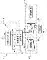
図1は、タービン部3と水素発生部5とを含む、水素と電気エネルギーを生成するための例示的な同時生産システム2を概略的に示す。この水素発生部は、改質装置4と分離ユニット12を含む。タービン部は、燃焼器6、圧縮機24、ガスタービン26、及びロータ46を含み、該ロータによってタービン26が圧縮機24を駆動する。改質装置4は、燃焼器6と結合され、燃焼器6からの燃焼熱が改質装置4の改質プロセスで利用される。以下に幾らか詳細に説明するように、同時生産システム2の基本構成要素は、殆ど公知であるが、公知のシステムに関する効率の改善は、システムの性能と効率を高める再循環流経路を備えるシステム構成要素の戦略的相互接続を通じて得られる。同時生産システムの効率は、その排気流からのエネルギー回収によって高められる。本明細書で説明される同時生産システムの種々の実施形態では、燃焼プロセスで使用される酸化剤は周囲空気である。燃焼に必要とされる酸素量を含む任意の他の酸化剤流を同じ目的のために使用できることは理解される。
FIG. 1 schematically illustrates an example simultaneous production system 2 for generating hydrogen and electrical energy, including a turbine section 3 and a hydrogen generation section 5. This hydrogen generator includes a reformer 4 and a
運転中、改質装置4は、燃料流8と蒸気40とを受けるように構成される。改質装置4では、燃料流8は、蒸気40と反応して水素リッチの改質油流44を生成する。改質油流44は分離ユニット12に送られ、該分離ユニット12は、ほぼ純粋な水素流16と排ガス流18とを生成するように構成される。幾つかの実施形態では、分離ユニット12は更に、二酸化炭素(CO2)リッチ流14を更に生成する。
During operation, the reformer 4 is configured to receive the
典型的には、蒸気を伴う天然ガスのような炭化水素燃料の改質は水素を生成する。このプロセスは、エネルギー集約的であり、大量の熱が改質プロセス全体で吸収される。天然ガスの主成分はメタン(CH4)であり、該メタンは、蒸気と2段階反応で反応し水素を生成する。改質プロセスの間、天然ガスは以下に示す反応(1)及び(2)に従って水素に転化される。
CH4 + H2O => CO + 3H2 (1)
CO + H2O => CO2 + H2 (2)
流入する燃料8の少なくとも一部は、改質装置4の改質プロセスによって転化されて水素を発生する。改質反応(1)は、ニッケルのような適切な蒸気改質触媒の存在下で起こる。改質反応(1)は、極めて吸熱性があり、約88,630BTU/moleの反応熱を有する。他の炭化水素燃料の改質反応は、同様に吸熱性である。改質油流44は、一酸化炭素(CO)、二酸化炭素(CO2)、水素(H2)、未使用燃料、及び水を含む。改質油流44は、分離ユニット12に供給され、該分離ユニットは、改質油流44から水素と一酸化炭素を分離して、二酸化炭素リッチ流14、水素リッチ流れ16、及び排ガス流18を生成する。1つの実施形態では、排ガス流18は燃料入口流8に再循環されて戻され、混合された流れは、蒸気と共に改質装置4に供給される。
Typically, reforming hydrocarbon fuels such as natural gas with steam produces hydrogen. This process is energy intensive and a large amount of heat is absorbed throughout the reforming process. The main component of natural gas is methane (CH 4 ), which reacts with steam in a two-stage reaction to produce hydrogen. During the reforming process, natural gas is converted to hydrogen according to reactions (1) and (2) shown below.
CH 4 + H 2 O => CO + 3H 2 (1)
CO + H 2 O => CO 2 + H 2 (2)
At least a part of the inflowing
吸熱改質反応(1)に必要とされる熱は、燃焼器6からの燃焼熱によって供給され、該燃焼器6は改質装置4と結合される。燃焼器6は、流入燃料流10と圧縮酸化剤流20を受けるように構成される。流入燃料流10と酸化剤流20は、予混合されて燃焼器6に噴射することができる。幾つかの実施形態では、燃料と酸化剤は、燃焼器6に別々に噴射することができる。幾つかの別の実施形態では、燃料と酸化剤は、燃焼器6に供給される前に、部分的に又は全てが混合される。流入燃料流10は、例えば、水素、天然ガス、メタン、ナフサ、ブタン、プロパン、ディーゼル、ケロシン、航空燃料、石炭派生燃料、バイオ燃料、含酸素炭化水素原料油、及びこれらの混合物などの任意の適切なガス又は液体を含むことができる。幾つかの実施形態では、燃料は、好ましくは水素又は天然ガス(NG)或いはこれらの混合物を含むことができる。他の幾つかの実施形態では、分離ユニット12からの排ガス流18の一部が、燃焼器6用の燃料として使用される。圧縮機24からの圧縮酸化剤20は、例えば、空気、酸素リッチ空気、酸素枯渇空気、及び/又は純酸素のような任意の適切な酸素含有ガスを含むことができる。運転中、例示的な圧縮機24は、固定ベーンと回転ブレードとからなる列を含む多段圧縮機である。燃焼器6における燃焼プロセスは、高温ガス流22を発生する。
The heat required for the endothermic reforming reaction (1) is supplied by the combustion heat from the combustor 6, and the combustor 6 is coupled to the reformer 4. Combustor 6 is configured to receive an
図1に戻ると、燃焼器6からの高温ガス流22は、ガスタービン26に供給される。同時生産システム2は更に、ガスタービン26に取り付けられた発電機28と、熱回収蒸気発生器(以下、HRSG)とを含む。ガスタービン26に供給される高温ガス流22の熱力学的膨張は、ガスタービン26を駆動する動力を生成し、その結果、該ガスタービンが発電機28を介して電気を発生させる。発電機28から生じた電気は、適切な形態に変換されて、配電電力供給網(図示せず)に供給される。ガスタービン26からの膨張ガス30は、該膨張ガス30の熱含有量を回収するためにHRSG32に供給される。水流34がHRSG32に供給され、該HRSGは、ガスタービン26からの高温の膨張ガス30からの回収熱を利用することによって蒸気38を発生する。HRSG32からの冷却された膨張ガス36は大気中へ排出される。
Returning to FIG. 1, the
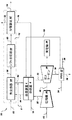
同時生産システムの種々の例示的な実施形態が図2、3、4及び図5に示される。図2、3、4及び図5に示すように、全ての例示的な実施形態は、図示された同時生産システム2の基本的構成要素を共用しており、これらの図では同じ要素は同じ参照符号で表される。 Various exemplary embodiments of simultaneous production systems are shown in FIGS. As shown in FIGS. 2, 3, 4 and 5, all exemplary embodiments share the basic components of the illustrated simultaneous production system 2, in which the same elements have the same reference It is represented by a sign.
同時生産システム50の第2の例示的な実施形態を図2に示す。第2の実施形態によれば、分離ユニット12は、熱交換器54、シフト反応器56、及び分離装置62を含む。運転上では、改質装置4は熱交換器54と流体連通している。水流52が熱交換器54に導入され、ここで改質装置4による改質油流44からの回収熱を利用することによって、水が蒸気64に転化される。熱交換器54で発生した蒸気64は、改質装置4での改質プロセスに使用される。
A second exemplary embodiment of the
改質装置4から発生した改質油流44は、水素(H2)、一酸化炭素(CO)、二酸化炭素(CO2)、水、及び未反応燃料を含む。改質油流44は、熱交換器54を使用して、約200度℃から約400度℃の間の温度まで冷却され、冷却された改質油流58を生成する。冷却された改質油流58内の一酸化炭素と水が反応して、更に二酸化炭素を生成することができる。このことは、水ガスシフト反応として知られる吸熱反応(2)によって達成することができる。CO2リーンな冷却改質油流58は、シフト反応器56に供給されて、触媒存在下で水ガスシフト反応を促進する。シフト反応器56からの出口流60は、未反応燃料、二酸化炭素、水、水素、及び微量の未転化一酸化炭素を含む。出口流60はまた、水素及び二酸化炭素のリッチ流と呼ぶこともできる。
The reformed
水素及び二酸化炭素リッチの、シフト反応器56からの出口流60は、分離装置62に供給され、分離装置62は更に、二酸化炭素分離器を含むことができる。二酸化炭素分離器は、限定ではないが圧力スイング吸着、化学吸着、及び膜分離を含む当該技術分野で公知の種々の技術を適用して、出口流60から二酸化炭素を分離することができる。
The
圧力スイング吸着(PSA)は、水素含有ガスの混合物から二酸化炭素を分離するのに使用することができる。高分圧でのPSA技術では、固体モレキュラーシーブは水素よりもより強く二酸化炭素を吸着することができる。その結果、高圧下において水素を含むガスの混合物が吸着ベッドを通過するときに、二酸化炭素がこの混合物から除去される。ベッドの再生は、減圧及びパージによって達成される。通常、重要な操作に対しては、複数の吸着容器が二酸化炭素の連続分離に使用され、この場合、1つの吸着ベッドが再生されている間は他の吸着ベッドが使用される。 Pressure swing adsorption (PSA) can be used to separate carbon dioxide from a mixture of hydrogen-containing gases. With PSA technology at high partial pressure, solid molecular sieves can adsorb carbon dioxide more strongly than hydrogen. As a result, carbon dioxide is removed from this mixture as it passes through the adsorption bed under high pressure. Bed regeneration is achieved by depressurization and purging. Typically, for critical operations, multiple adsorption vessels are used for continuous separation of carbon dioxide, in which case another adsorption bed is used while one adsorption bed is being regenerated.
ガス流から二酸化炭素を分離するための別の技術は、酸化カルシウム(Ca O)及び酸化マグネシウム(MgO)又はこれらの組合せなどの酸化物を使用する化学吸着である。1つの実施形態では、高温高圧下において、CO2はCaOによって吸着されて炭酸カルシウム(CaCO3)を形成し、これによりガス混合物からCO2を除去する。吸着剤CaOは、同様にCaCO3をCaOに改質可能な、CaCO3のか焼によって再生される。 Another technique for separating carbon dioxide from a gas stream is chemisorption using oxides such as calcium oxide (Ca 2 O) and magnesium oxide (MgO) or combinations thereof. In one embodiment, under high temperature and pressure, CO 2 is adsorbed by CaO to form calcium carbonate (CaCO 3 ), thereby removing CO 2 from the gas mixture. The adsorbent CaO is regenerated by calcination of CaCO 3 which can similarly modify CaCO 3 to CaO.
膜分離技術もまた、ガス流から二酸化炭素を分離するのに使用することができる。膜プロセスは一般に、吸着プロセスよりもエネルギー効率が優れ且つ操作が容易である。高温の二酸化炭素分離のために使用される膜は、CO2に対して選択的であるゼオライト及びセラミック膜を含む。しかしながら、膜技術の分離効率は低く、二酸化炭素の完全分離を膜分離によって達成するのは困難である可能性がある。通常膜分離器は、高圧においてより効率的に機能し、シフト反応器56からの出口流60から二酸化炭素を分離するために膜分離器を使用することは、CO2の分離の前に出口流60を更に加圧することによって達成することができる。
Membrane separation techniques can also be used to separate carbon dioxide from a gas stream. Membrane processes are generally more energy efficient and easier to operate than adsorption processes. The membranes used for high temperature carbon dioxide separation include zeolite and ceramic membranes is selective to CO 2. However, the separation efficiency of membrane technology is low, and complete separation of carbon dioxide can be difficult to achieve by membrane separation. Normally, membrane separators function more efficiently at high pressures, and using a membrane separator to separate carbon dioxide from the
出口流60からCO2を分離するのに使用される更に別の技術は、限定ではないが、アミンを用いたCO2の化学吸着を含むことができる。出口流60は、アミンを用いる二酸化炭素の化学吸着を用いるのに好適な温度まで冷却することができる。この技術は、比較的低温で二酸化炭素を吸着する能力を有し、リッチソルベントの温度を高めることによってより容易に再生されるアルカノールアミン溶媒に基づく。二酸化炭素リッチ流14は、リッチソルベントの再生後に得られる。この技術で使用される溶媒は、トリエタノールアミン、モノエタノールアミン、ジエタノールアミン、ジイソプロパノールアミン、ジグリコールアミン、メチルジエタノールアミンを含むことができる。
Yet another technique used to separate CO 2 from the
幾つかの実施形態では、二酸化炭素分離器は、出口流60から二酸化炭素を分離するためにPSA技術が使用される少なくとも1つの吸着ベッドを含むことができる。他の幾つかの実施形態では、二酸化炭素分離器は、化学吸着技術が使用される少なくとも1つの吸着容器を含むことができる。更に別の実施形態では、二酸化炭素分離器は、少なくとも1つの膜分離器を含む。本明細書で説明した種々の技術を使用して、二酸化炭素リッチ流14は分離装置62から生成される。二酸化炭素リッチ流14は、任意の他の工業用途に対して移出することができる。
In some embodiments, the carbon dioxide separator can include at least one adsorption bed in which PSA technology is used to separate carbon dioxide from the
分離装置62は更に、水素分離器を含むことができる。他のガスから水素を分離してほぼ純粋な水素流16を生成する方法は、PSA及び膜分離を含む。種々のポリマーは、比較的低温で機能する水素選択膜に用いることができる。1つの実施形態では、水素分離効率は、PSAユニットとCO2分離膜を組合せることによって高めることができる。第1段階で、PSA技術によってH2が分離される。次の段階では、CO2選択膜によってCO2が分離される。高分子膜の中には、比較的低温でCO2分離における良好な選択透過性を示すものがある。
Separation device 62 can further include a hydrogen separator. Methods for separating hydrogen from other gases to produce a substantially
幾つかの実施形態では、水素分離器は、極低温分離技術を用いることができる。極低温分離は、複数分別及び複数製品の回収が重要である場合に用いることができる。1つの実施形態では、シフト反応器56からの出口流60は、約900psiaまで圧縮され、次にCO2を液化する復水器を使用して室温まで冷却される。水素は、このプロセスから気体として回収することができ、一方、CO2は、復水器の下部から液体として取り出すことができる。水素分離器は更に、湿分分離器と一体化することができる。
In some embodiments, the hydrogen separator can use a cryogenic separation technique. Cryogenic separation can be used when multiple fractionation and multiple product recovery are important. In one embodiment, the
図2に示すように、3つの流れ、すなわちほぼ純粋な水素流16、二酸化炭素リッチ流14及び排ガス18が分離装置62から回収される。分離装置62からの排ガス流18は、未反応燃料、未分離水素、及び水を含む。幾つかの実施形態では、分離装置62からの排ガス流18は更に、微量の二酸化炭素と一酸化炭素とを含む。流れ18は、流入する燃料流8と共に改質装置4に再利用して戻される。
As shown in FIG. 2, three streams are recovered from the separator 62, namely a substantially
1つの実施形態では、水素流16の一部が、燃焼器6における燃焼プロセスの燃料として使用される。図2に示すこの例示的な実施形態では、完全な二酸化炭素分離が達成される。燃焼器で燃焼される燃料がほぼ純粋な水素を含むときには、燃焼器6の燃焼プロセス中に二酸化炭素は形成されない。従って、燃焼器から発生する高温ガス22は二酸化炭素を含まず、大気中に排出されるガス36は、二酸化炭素を放出しない。改質プロセスで生成される二酸化炭素は、濃縮二酸化炭素流14として分離されて、該濃縮二酸化炭素流は、二酸化炭素の需要に応じて商業市場で接収又は販売される。図2に示すように、HRSG32で発生した蒸気の一部66は、吸熱改質反応(1)及び発熱水ガスシフト反応(2)に対し十分な蒸気量を供給するために改質装置4に再循環されて戻される。幾つかの実施形態では、HRSG32で発生した蒸気の別の部分38は、付加的な発電用に蒸気タービン(図示せず)に送られる。
In one embodiment, a portion of the
図3は、分離装置62からの排ガス流18が、燃焼器6に再循環されて戻される、第3の例示的な同時生産システムを示す。上記で説明したように、排ガス流18は通常、未燃焼燃料、H2、CO、及びCO2を含む。分離装置62で濃縮二酸化炭素流14として二酸化炭素が分離されたことに起因して、出口流60内の二酸化炭素は、排ガス流18が燃焼器6に再循環される前にほぼ除去される。その結果、燃焼器6で発生して、続いて排ガス36として大気中に放出される二酸化炭素は、従来のコンバインドサイクル発電システムと比較して少ない二酸化炭素量を含む。排ガス18を燃焼器6に再循環する前の予燃焼段階で二酸化炭素が除去されるので、二酸化炭素の分離は、図3に示すように同時生産システム内で部分的に達成される。シフト反応器からの出口流60が二酸化炭素において十分に濃縮されていると、予燃焼段階での二酸化炭素の除去はより容易に達成される。燃焼器からの高温圧縮ガスは、燃焼器6からの高温圧縮ガス流22の二酸化炭素濃度を希薄化する窒素を含むので、いかなる燃焼後分離も達成することは困難である。
FIG. 3 shows a third exemplary simultaneous production system in which the
図4は、排ガス流18が第2の燃焼室84と流体連通している、第4の例示的な同時生産システムを示す。分離装置62からの排ガス流18は、空気のような酸化剤流82と共に第2の燃焼室84に供給される。幾つかの実施形態では、酸化剤流82は、ほぼ純粋な酸素を含み、ここでは第2の改質装置からの排気流86は、窒素のようなどのような希薄剤をも含まない。排気流86は、HRSG32で冷却され、ここでは排気流86の流路は、ガスタービン26からのタービン排気30の流路から分離される。燃焼器6で燃焼される燃料がほぼ純粋な水素を含むので、図4に示す同時生産システムの利点は二酸化炭素を分離することである。タービン排気30及び第2の燃焼室84からの排気流86による回収熱から発生した蒸気の一部66は、改質装置4に再循環される。蒸気の一部38は、更なる発電のために蒸気タービン(図示せず)に供給することができる。幾つかの実施形態では、HRSG32からの冷却された排気流36及び85は大気中に排出される。
FIG. 4 shows a fourth exemplary simultaneous production system in which the
図5は、圧縮空気流20が復熱装置92へ向けて配向される第5の例示的な同時生産システムを示しており、この復熱装置92は、分離された流路を含む既知の熱交換器形式である。圧縮空気流20は、第1の復熱装置流路96を通り復熱装置92に流入する。タービン排気30は、第2の燃焼器84からの排気86と混合されて、混合タービン排気流88を形成する。幾つかの他の実施形態では、第2の燃焼器84からの排気86及びガスタービン26からの排気30は、復熱装置92において分離された流路を有し、ここでは燃焼器84への酸化剤流82は、ほぼ純粋な酸素を含む。図5に示すように、混合タービン排気流88は、第2の復熱装置流路99で復熱装置92内を通過し、これによってタービン排気88からの熱は、圧縮空気流20とタービン排気流88とが混合することなく圧縮空気流20に伝達される。加熱された圧縮空気流98は、復熱装置92を出て燃焼器6に流れ、そこで酸化剤を供給する。タービン排気88を用いて圧縮空気流20を加熱することにより、酸化剤の温度を上昇させるための従来型ヒータ又は再生式熱交換器のコストが回避され、更にタービン排気流88は大気中に排出される前に冷却される。続いて、冷却されたタービン排気流94は、HRSG32に供給され、ここで流入水流34が加熱されて蒸気を生成する。冷却されたタービン排気36は大気中に排出され、発生した蒸気66は改質装置4に再循環されて戻される。
FIG. 5 shows a fifth exemplary simultaneous production system in which the
図1、2、3、4、及び図5に示す本発明の技術による全ての例示的な実施形態では、改質装置4と燃焼器6は結合されている。燃焼器6の冷却は、燃料と蒸気を改質する吸熱型改質によって達成される。吸熱型改質プロセスで吸収される有意な熱によって、燃焼器6のライナーを冷却することができ、更に燃焼器の操作性と火炎安定性が確実に改善される。本明細書で開示される同時生産システムはまた、上記の部分で説明した種々の実施形態によって示されるように、燃焼器6内で水素リッチ燃料を燃焼することによって低い火炎温度が達成されるので、NOxの生成を有意に削減することが保証される。 In all exemplary embodiments in accordance with the techniques of the present invention shown in FIGS. 1, 2, 3, 4 and 5, the reformer 4 and the combustor 6 are combined. Cooling of the combustor 6 is achieved by endothermic reforming that reforms fuel and steam. The significant heat absorbed in the endothermic reforming process can cool the liner of the combustor 6 and further improve the combustor operability and flame stability. The simultaneous production system disclosed herein also achieves low flame temperatures by combusting hydrogen rich fuel in the combustor 6, as shown by the various embodiments described in the above section. , it is guaranteed to significantly reduce the formation of NO x.
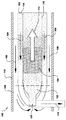
図6は、改質装置が燃焼器と結合された例示的な燃焼器−改質装置の概略図を示す。この結合された改質装置−燃焼器100は、円筒状圧力シェル118内に配置されるように構成される。圧力シェルの厚さは、改質装置−燃焼器100の最大作動圧力に依存する適正規準により設計される。改質プロセスは、燃焼器110と密接に接触した管102内で行われ、改質装置102と燃焼器110は同心である。圧縮空気は、空気流106で示すように、圧力シェル内の環状空間108を貫流する。空気は、エントリーポート120を通って燃焼器110に流入する。水素、天然ガス又は排ガスなどの燃料もまた、同じ位置(図示せず)において燃焼器110に送られる。空気と燃料の混合は、混合ゾーン122で達成される。燃焼ゾーン124は、改質装置102と接触する表面116を通って半径方向及び軸方向に放散する燃焼熱を主に発生する。燃焼器110の燃焼ゾーン124の標準温度は、改質プロセスに多くの熱エネルギーを与えるのに十分な温度範囲である約1700度℃まで上昇することができる。燃焼器110から改質装置102への熱伝達プロセスにおいて、燃焼器のライナーは冷却され、これによって燃焼器の寿命が増大する。改質中の燃料と蒸気の混合体は、混合体流路104で示すように、改質管102内の環状空間内を循環する。通常CO2、CO、H2、水、及び未燃燃料を含む改質油は、開口114を通って改質装置102を出る。
FIG. 6 shows a schematic diagram of an exemplary combustor-reformer with the reformer combined with the combustor. The combined reformer-
図7は、燃焼器と改質装置が結合された、更に別の例示的な改質装置燃焼器130の上部分を示す。燃焼器134は、流路140で示す燃焼ガスの流れに沿って容器の断面が減少する圧力容器である。この燃焼器は、中心線154に沿って360度回転したときの図7に示すような形状の環状構造である。改質装置132は、同じ中心線154に沿って360度回転した別の環状構造である。この燃焼器134は、改質装置132に密着して接触している上部ライナー148と、底部ライナー160とを備える。この燃焼器134は更に、燃料及び酸化剤が通過して燃焼器134に流入できるポートを有するように構成された予混合器150を備える。幾つかの実施形態では、予混合された燃料及び酸化剤は、スワラーを含むノズルを通って燃焼器134に噴射され、該スワラーは、流入する酸化剤に回転を与える複数のスワールベーンと、回転する酸化剤流に燃料を分配する複数の燃料スポークとを含む。空気などの酸化剤146は、燃焼器134の燃焼と底部ライナー160の冷却に使用される。燃料及び酸化剤は、燃焼器134内での反応の前に、予混合燃料ノズル内の環状通路において混合される。改質装置132は、蒸気を導入するための通路131と、改質燃料を導入するための通路158とを含む。改質燃料と蒸気の混合体は、通路136を貫流し、ここでは吸熱反応(1)が、燃焼器134から改質装置132に伝達される熱を吸収する。熱エネルギーは、伝導及び対流による半径方向及び軸方向の熱放散によって燃焼器134から改質装置132に伝達されることで、燃焼器134の外部ライナー148を冷却する。改質装置132は更に、ニッケルのような改質触媒を含有する触媒ベッド156を含む。改質油は、流路138を通って改質装置132から流出する。燃焼器134の内部ライナー160は、圧縮空気146の一部を用いて冷却され、ここで空気142は、燃焼器の内部ライナー160と底部シェル162との間の環状空間144を通って循環する。
FIG. 7 shows the upper portion of yet another
上述のように、本技術による種々の実施形態では、燃焼器の冷却は、天然ガスなどの燃料の吸熱型改質によって達成され、この冷却によってシステムの全体効率が改善された水素及び電力の同時生産が可能となる。吸熱型改質プロセスで熱が有意に吸収されることによって、燃焼器のライナーを冷却可能とし、且つ火炎の安定性を維持又は改善することが保証される。 As described above, in various embodiments in accordance with the present technology, combustor cooling is achieved by endothermic reforming of fuels such as natural gas, and this cooling improves the overall efficiency of the system with simultaneous hydrogen and power. Production becomes possible. Significant heat absorption in the endothermic reforming process ensures that the combustor liner can be cooled and that flame stability is maintained or improved.
同時生産システムで生成された水素の一部が燃焼器用燃料として使用される場合には、このことによって、高水素含有燃料が燃焼器内で燃焼されるときに低い火炎温度を達成することができるので、NOx生成の有意な削減が保証される。分離ユニット内で予燃焼により二酸化炭素を分離することによって、大気中へのCO2排出が確実に隔離及び制限される。開示された同時生産方法は、発電からの廃熱の一部を水素生産に移すことによってプラント性能を改善し、従ってプラントの効率及び稼動性を改善する。本明細書で開示された同時生産システムは、改質装置からの改質油流による水素の生産と、需要に応じた電気エネルギーの発生とを制御する柔軟性を有する。開示された同時生産システムで生成された水素は、幾つかの方法で利用することができる。生成された水素は、燃焼器に再循環して、大気中に対して二酸化炭素の無い排出を達成する燃料として使用することができる。生成された水素は、容器、シリンダ又はメタルハイドライドなどの固体物質を含むことができる水素貯蔵ユニット内に貯蔵することができる。次いで、生成された水素は、気体の形、或いは液化プラントを用いるような液体の形で輸送することができる。生成された水素はまた、付加的な発電のための1つ又はそれ以上の燃料電池から構成された燃料電池システムの燃料として用いることができる。 If a portion of the hydrogen produced in the co-production system is used as a combustor fuel, this can achieve a low flame temperature when the high hydrogen content fuel is combusted in the combustor. As such, a significant reduction in NO x production is guaranteed. By separating carbon dioxide by pre-combustion in the separation unit, CO 2 emissions to the atmosphere are reliably sequestered and limited. The disclosed simultaneous production method improves plant performance by transferring some of the waste heat from power generation to hydrogen production, thus improving plant efficiency and operability. The simultaneous production system disclosed herein has the flexibility to control the production of hydrogen by the reformed oil stream from the reformer and the generation of electrical energy according to demand. The hydrogen produced in the disclosed simultaneous production system can be utilized in several ways. The produced hydrogen can be recycled to the combustor and used as a fuel to achieve carbon dioxide-free emissions to the atmosphere. The produced hydrogen can be stored in a hydrogen storage unit that can contain a solid material such as a container, cylinder or metal hydride. The produced hydrogen can then be transported in gaseous form or liquid form such as using a liquefaction plant. The produced hydrogen can also be used as fuel in a fuel cell system composed of one or more fuel cells for additional power generation.
本発明の種々の実施形態を本発明に適合する種々のニーズを実現する点において説明した。これらの実施形態は、本発明の様々な実施形態の原理の例証に過ぎないことを認識されたい。請求項に示す参照符号は、本発明の範囲を狭めるものではなく、より容易に理解することを意図するものである。 Various embodiments of the present invention have been described in fulfilling various needs consistent with the present invention. It should be recognized that these embodiments are merely illustrative of the principles of various embodiments of the present invention. Reference numerals appearing in the claims do not narrow the scope of the invention but are intended to be more easily understood.
4 改質装置
6 燃焼器
8 改質装置燃料
10 燃料
12 分離ユニット
18 排ガス
22 高温圧縮ガス
26 ガスタービン
30 膨張ガス
32 熱回収蒸気発生器、HRSG
44 改質油
54 熱交換器
56 水ガスシフト反応器
60 水素及び二酸化炭素リッチ流
4 reformer 6
44 reformed oil 54 heat exchanger 56 water
Claims (10)
改質装置燃料(8)及び蒸気を受けて、水素リッチ改質油(44)を生成するように構成された改質装置(4)と、
前記改質装置(4)と流体連通し、前記改質油(44)を受けて該改質油(44)から水素を分離して排ガス(18)を生成するように構成された分離ユニット(12)と、
燃焼用に燃料(10)を受けて熱エネルギーと高温圧縮ガス(22)とを生成するように構成され、前記改質装置(4)と結合された燃焼器(6)と、
前記高温圧縮ガス(22)を膨張させて電気エネルギーと膨張ガス(30)とを生成するガススタービン(26)と、
を備え、
前記燃焼器(6)からの熱エネルギーの少なくとも一部が、前記改質装置(4)内で前記改質油(44)を生成するのに使用されることを特徴とするシステム。 A system for simultaneous production of hydrogen and electrical energy,
A reformer (4) configured to receive the reformer fuel (8) and steam to produce a hydrogen-rich reformate (44);
A separation unit (in fluid communication with the reformer (4)) configured to receive the reformed oil (44) and separate hydrogen from the reformed oil (44) to produce exhaust gas (18). 12)
A combustor (6) configured to receive fuel (10) for combustion to produce thermal energy and hot compressed gas (22), coupled to the reformer (4);
A gas turbine (26) for expanding the hot compressed gas (22) to produce electrical energy and expanded gas (30);
With
A system characterized in that at least part of the thermal energy from the combustor (6) is used to produce the reformed oil (44) in the reformer (4).
改質装置燃料と蒸気を受けて、水素リッチ改質油(44)を生成するように構成された改質装置(4)と、
燃焼用に燃料(10)を受けて熱エネルギーと高温圧縮ガス(22)とを生成するように構成され、前記改質装置(4)と結合された燃焼器(6)と、
前記改質装置(4)と流体連通し、前記改質油(44)を受けて前記改質油(44)から水素を分離して排ガス(18)を生成するように構成された分離ユニット(12)と、
を備え、
前記燃焼器(6)からの前記熱エネルギーの少なくとも一部が、前記改質装置(4)内で前記改質油(44)を生成するのに使用され、
前記高温圧縮ガス(22)を膨張させて電気エネルギーと膨張ガス(30)とを生成するガススタービン(26)が更に設けられ、
前記燃焼器(6)からの熱エネルギーの少なくとも一部が、前記改質装置(4)内で前記改質油(44)を生成するのに使用され、前記分離ユニット(12)が前記改質油(44)から二酸化炭素を分離して、前記排ガス(18)の少なくとも一部を前記改質装置(4)に再循環させるように構成されたシステム。 A system for simultaneous production of hydrogen and electrical energy,
A reformer (4) configured to receive reformer fuel and steam to produce hydrogen-rich reformate (44);
A combustor (6) configured to receive fuel (10) for combustion to produce thermal energy and hot compressed gas (22), coupled to the reformer (4);
A separation unit (in fluid communication with the reformer (4)) configured to receive the reformed oil (44) and separate hydrogen from the reformed oil (44) to produce exhaust gas (18). 12)
With
At least a portion of the thermal energy from the combustor (6) is used to produce the reformed oil (44) in the reformer (4);
A gas turbine (26) for expanding the hot compressed gas (22) to generate electrical energy and an expanded gas (30);
At least a portion of the thermal energy from the combustor (6) is used to produce the reformed oil (44) in the reformer (4), and the separation unit (12) is used for the reforming. A system configured to separate carbon dioxide from oil (44) and recirculate at least a portion of the exhaust gas (18) to the reformer (4).
改質装置燃料と蒸気との混合体を改質装置(4)内で改質して水素リッチ改質油(44)を生成する段階と、
前記改質油(44)から水素を分離して排ガス(18)を生成する段階と、
前記改質装置(4)と結合された燃焼器(6)内で燃料を燃焼させて熱エネルギーと高温圧縮ガス(22)とを生成する段階と、
前記高温圧縮ガス(22)を膨張中のガススタービン(26)内で膨張させて電気エネルギーと膨張ガス(30)とを生成する段階と、
を含み、
前記燃焼器(6)からの前記熱エネルギーの少なくとも一部が、前記改質装置(4)内で前記改質油(44)を生成するのに使用されるようにする方法。 A method for the simultaneous production of hydrogen and electrical energy comprising:
Reforming the reformer fuel and steam mixture in the reformer (4) to produce a hydrogen rich reformate (44);
Separating hydrogen from the reformed oil (44) to produce exhaust gas (18);
Combusting fuel in a combustor (6) coupled to the reformer (4) to produce thermal energy and hot compressed gas (22);
Expanding the hot compressed gas (22) in an expanding gas turbine (26) to produce electrical energy and expanded gas (30);
Including
A method in which at least a portion of the thermal energy from the combustor (6) is used to produce the reformed oil (44) in the reformer (4).
燃料及び酸化剤を受けて燃焼させ、高温圧縮ガス(22)及び熱エネルギーを生成するように構成された燃焼器(6)と、
前記燃焼器(6)に密接して接触し、改質装置燃料及び蒸気を受けて水素リッチ改質油(44)を生成するように構成された改質装置(4)と、
を備え、
前記改質装置(4)が前記燃焼器(6)と結合され、前記燃焼器(6)からの前記熱エネルギーの少なくとも一部が、前記改質装置(4)内で前記改質油(44)を生成するのに使用されることを特徴とする燃焼器改質装置システム。 A combustor reformer system comprising:
A combustor (6) configured to receive and burn fuel and oxidant to produce hot compressed gas (22) and thermal energy;
A reformer (4) configured to be in intimate contact with the combustor (6) and to receive reformer fuel and steam to produce hydrogen-rich reformate (44);
With
The reformer (4) is coupled to the combustor (6), and at least a portion of the thermal energy from the combustor (6) is transferred to the reformed oil (44) in the reformer (4). A combustor reformer system characterized in that it is used to produce
Applications Claiming Priority (1)
| Application Number | Priority Date | Filing Date | Title |
|---|---|---|---|
| US10/810,471 US7752848B2 (en) | 2004-03-29 | 2004-03-29 | System and method for co-production of hydrogen and electrical energy |
Publications (1)
| Publication Number | Publication Date |
|---|---|
| JP2005281131A true JP2005281131A (en) | 2005-10-13 |
Family
ID=34887658
Family Applications (1)
| Application Number | Title | Priority Date | Filing Date |
|---|---|---|---|
| JP2005090941A Pending JP2005281131A (en) | 2004-03-29 | 2005-03-28 | System and method for co-production of hydrogen and electrical energy |
Country Status (4)
| Country | Link |
|---|---|
| US (1) | US7752848B2 (en) |
| EP (1) | EP1582502B1 (en) |
| JP (1) | JP2005281131A (en) |
| CN (1) | CN1676460B (en) |
Cited By (7)
| Publication number | Priority date | Publication date | Assignee | Title |
|---|---|---|---|---|
| JP2007302553A (en) * | 2006-05-09 | 2007-11-22 | Ifp | Method for simultaneous production of hydrogen rich gas and electric power by steam reforming of hydrocarbon fraction through heat supply by on-site hydrogen combustion |
| JP2008179496A (en) * | 2007-01-23 | 2008-08-07 | Toho Gas Co Ltd | Apparatus and method for producing hydrogen |
| JP2008180213A (en) * | 2006-12-18 | 2008-08-07 | General Electric Co <Ge> | IMPROVED SYSTEM AND METHOD FOR REDUCING NOx EMISSION |
| JP2009508790A (en) * | 2005-09-19 | 2009-03-05 | レール・リキード−ソシエテ・アノニム・プール・レテュード・エ・レクスプロワタシオン・デ・プロセデ・ジョルジュ・クロード | Method for producing synthesis gas using oxygen-containing gas produced by at least one gas turbine |
| JP2011207755A (en) * | 2010-03-30 | 2011-10-20 | General Electric Co <Ge> | Fluid cooled reformer and method for cooling reformer |
| KR20190080354A (en) * | 2017-12-28 | 2019-07-08 | 대우조선해양 주식회사 | Floating Power Plant and Employment Method therefor |
| JP2020501076A (en) * | 2016-11-09 | 2020-01-16 | 8 リバーズ キャピタル,エルエルシー | System and method for electric power production with integrated production of hydrogen |
Families Citing this family (119)
| Publication number | Priority date | Publication date | Assignee | Title |
|---|---|---|---|---|
| JP4139338B2 (en) * | 2004-02-12 | 2008-08-27 | 本田技研工業株式会社 | Fuel gas production equipment |
| US7470293B2 (en) * | 2004-10-29 | 2008-12-30 | Idatech, Llc | Feedstock delivery systems, fuel processing systems, and hydrogen generation assemblies including the same |
| NO20051895D0 (en) * | 2005-04-19 | 2005-04-19 | Statoil Asa | Process for the production of electrical energy and CO2 from a hydrocarbon feedstock |
| JP4810138B2 (en) * | 2005-06-30 | 2011-11-09 | 株式会社東芝 | Hydrogen production equipment |
| US7506685B2 (en) * | 2006-03-29 | 2009-03-24 | Pioneer Energy, Inc. | Apparatus and method for extracting petroleum from underground sites using reformed gases |
| US9605522B2 (en) * | 2006-03-29 | 2017-03-28 | Pioneer Energy, Inc. | Apparatus and method for extracting petroleum from underground sites using reformed gases |
| US20070269690A1 (en) * | 2006-05-22 | 2007-11-22 | Doshi Kishore J | Control system, process and apparatus for hydrogen production from reforming |
| US7939051B2 (en) * | 2006-05-23 | 2011-05-10 | Idatech, Llc | Hydrogen-producing fuel processing assemblies, heating assemblies, and methods of operating the same |
| US8015823B2 (en) | 2006-08-21 | 2011-09-13 | United Technologies Corporation | Endothermic cracking aircraft fuel system |
| US7648566B2 (en) * | 2006-11-09 | 2010-01-19 | General Electric Company | Methods and apparatus for carbon dioxide removal from a fluid stream |
| MY149305A (en) | 2006-11-30 | 2013-08-30 | Shell Int Research | Systems and processes for producing hydrogen and carbon dioxide |
| US7966829B2 (en) * | 2006-12-11 | 2011-06-28 | General Electric Company | Method and system for reducing CO2 emissions in a combustion stream |
| US8616294B2 (en) | 2007-05-20 | 2013-12-31 | Pioneer Energy, Inc. | Systems and methods for generating in-situ carbon dioxide driver gas for use in enhanced oil recovery |
| US9464573B2 (en) * | 2007-09-25 | 2016-10-11 | Airbus Sas | Method for operating a gas turbine engine, power supplying device for conducting such method and aircraft using such method |
| CN101836318B (en) * | 2007-10-25 | 2013-02-27 | Utc电力公司 | Reduced generation of ammonia in nickel catalyst of reformer |
| DE102007056841A1 (en) * | 2007-11-23 | 2009-05-28 | Forschungszentrum Jülich GmbH | Membrane power plant and method of operating such |
| US7985399B2 (en) * | 2008-03-27 | 2011-07-26 | Praxair Technology, Inc. | Hydrogen production method and facility |
| EP2268897B1 (en) | 2008-03-28 | 2020-11-11 | Exxonmobil Upstream Research Company | Low emission power generation and hydrocarbon recovery system and method |
| US8734545B2 (en) | 2008-03-28 | 2014-05-27 | Exxonmobil Upstream Research Company | Low emission power generation and hydrocarbon recovery systems and methods |
| WO2009150679A1 (en) * | 2008-06-12 | 2009-12-17 | Processi Innovativi Srl | Method of and apparatus for manufacturing hydrogen and produce power |
| US8450536B2 (en) | 2008-07-17 | 2013-05-28 | Pioneer Energy, Inc. | Methods of higher alcohol synthesis |
| US20100037521A1 (en) | 2008-08-13 | 2010-02-18 | L'Air Liquide Societe Anonyme Pour L'Etude et l'Exploitatation Des Procedes Georges Claude | Novel Steam Reformer Based Hydrogen Plant Scheme for Enhanced Carbon Dioxide Recovery |
| US7753972B2 (en) * | 2008-08-17 | 2010-07-13 | Pioneer Energy, Inc | Portable apparatus for extracting low carbon petroleum and for generating low carbon electricity |
| FR2936507B1 (en) * | 2008-09-29 | 2011-04-08 | Inst Francais Du Petrole | PROCESS FOR THE PRODUCTION OF HYDROGEN WITH TOTAL CO2 CAPTATION AND RECYCLING OF NON-CONVERTED METHANE |
| BRPI0920139A2 (en) | 2008-10-14 | 2015-12-22 | Exxonmobil Upstream Res Co | combustion system, combustion control method, and combustion system. |
| FR2938522B1 (en) * | 2008-11-20 | 2010-12-17 | Inst Francais Du Petrole | PROCESS FOR THE PRODUCTION OF HYDROGEN WITH TOTAL CO2 CAPTATION AND RECYCLING OF NON-CONVERTED METHANE |
| US20100175379A1 (en) * | 2009-01-09 | 2010-07-15 | General Electric Company | Pre-mix catalytic partial oxidation fuel reformer for staged and reheat gas turbine systems |
| CA2881239C (en) | 2009-01-21 | 2017-02-28 | Res Usa, Llc | System and method for dual fluidized bed gasification |
| US8137422B2 (en) | 2009-06-03 | 2012-03-20 | Air Products And Chemicals, Inc. | Steam-hydrocarbon reforming with reduced carbon dioxide emissions |
| CA2764450C (en) | 2009-06-05 | 2018-02-13 | Exxonmobil Upstream Research Company | Combustor systems and methods for using same |
| WO2011028322A1 (en) * | 2009-09-01 | 2011-03-10 | Exxonmobil Upstream Research Company | Low emission power generation and hydrocarbon recovery systems and methods |
| FR2949772A1 (en) * | 2009-09-04 | 2011-03-11 | Total Raffinage Marketing | Producing a synthesis gas containing hydrogen from a hydrocarbon charge including e.g. methane or naphtha, comprises transforming hydrocarbon charge into synthesis gas in vapor-reforming furnace, and treating the synthesis gas |
| US7937948B2 (en) * | 2009-09-23 | 2011-05-10 | Pioneer Energy, Inc. | Systems and methods for generating electricity from carbonaceous material with substantially no carbon dioxide emissions |
| US8187363B2 (en) * | 2009-11-05 | 2012-05-29 | Air Liquide Process & Construction, Inc. | PSA tail gas preheating |
| AU2010318595C1 (en) | 2009-11-12 | 2016-10-06 | Exxonmobil Upstream Research Company | Low emission power generation and hydrocarbon recovery systems and methods |
| JP5495749B2 (en) * | 2009-12-10 | 2014-05-21 | 三菱重工業株式会社 | Hydrogen production facility and power plant |
| US7818969B1 (en) | 2009-12-18 | 2010-10-26 | Energyield, Llc | Enhanced efficiency turbine |
| US8230826B2 (en) * | 2010-04-08 | 2012-07-31 | Ford Global Technologies, Llc | Selectively storing reformate |
| JP5906555B2 (en) | 2010-07-02 | 2016-04-20 | エクソンモービル アップストリーム リサーチ カンパニー | Stoichiometric combustion of rich air by exhaust gas recirculation system |
| SG10201505209UA (en) | 2010-07-02 | 2015-08-28 | Exxonmobil Upstream Res Co | Low emission power generation systems and methods |
| US9732673B2 (en) | 2010-07-02 | 2017-08-15 | Exxonmobil Upstream Research Company | Stoichiometric combustion with exhaust gas recirculation and direct contact cooler |
| TWI593878B (en) | 2010-07-02 | 2017-08-01 | 艾克頌美孚上游研究公司 | Systems and methods for controlling combustion of a fuel |
| MY164051A (en) | 2010-07-02 | 2017-11-15 | Exxonmobil Upstream Res Co | Low emission triple-cycle power generation systems and methods |
| FR2962993B1 (en) * | 2010-07-23 | 2013-11-01 | IFP Energies Nouvelles | PROCESS FOR PRODUCING HYDROGEN WITH INTERMEDIATE PRESSURE PURGING |
| WO2012018458A1 (en) | 2010-08-06 | 2012-02-09 | Exxonmobil Upstream Research Company | System and method for exhaust gas extraction |
| EP2601393B1 (en) | 2010-08-06 | 2020-01-15 | Exxonmobil Upstream Research Company | Systems and methods for optimizing stoichiometric combustion |
| US20120055168A1 (en) | 2010-09-08 | 2012-03-08 | General Electric Company | System and method for producing hydrogen rich fuel |
| US8869502B2 (en) * | 2011-01-13 | 2014-10-28 | General Electric Company | Fuel reformer system for a turbomachine system |
| TWI563165B (en) | 2011-03-22 | 2016-12-21 | Exxonmobil Upstream Res Co | Power generation system and method for generating power |
| TWI563166B (en) | 2011-03-22 | 2016-12-21 | Exxonmobil Upstream Res Co | Integrated generation systems and methods for generating power |
| TWI593872B (en) | 2011-03-22 | 2017-08-01 | 艾克頌美孚上游研究公司 | Integrated system and methods of generating power |
| TWI564474B (en) | 2011-03-22 | 2017-01-01 | 艾克頌美孚上游研究公司 | Integrated systems for controlling stoichiometric combustion in turbine systems and methods of generating power using the same |
| CN102213142B (en) * | 2011-05-30 | 2014-01-01 | 重庆大学 | Method for increasing thermal efficiency of reheating cycle of gas turbine based on methane reformation |
| CN102322353B (en) * | 2011-05-30 | 2014-01-01 | 重庆大学 | Method for increasing thermal efficiency of cycle of combustion turbine |
| CN102220903B (en) * | 2011-05-30 | 2014-01-01 | 重庆大学 | Method for raising cyclic thermal performance of gas turbine based on combustion-reforming of methane |
| US9810050B2 (en) | 2011-12-20 | 2017-11-07 | Exxonmobil Upstream Research Company | Enhanced coal-bed methane production |
| US9353682B2 (en) | 2012-04-12 | 2016-05-31 | General Electric Company | Methods, systems and apparatus relating to combustion turbine power plants with exhaust gas recirculation |
| US9784185B2 (en) | 2012-04-26 | 2017-10-10 | General Electric Company | System and method for cooling a gas turbine with an exhaust gas provided by the gas turbine |
| US10273880B2 (en) | 2012-04-26 | 2019-04-30 | General Electric Company | System and method of recirculating exhaust gas for use in a plurality of flow paths in a gas turbine engine |
| EP2674394B1 (en) * | 2012-06-12 | 2016-03-16 | Air Products And Chemicals, Inc. | Hydrogen production with co2 capture |
| BR112015001008A2 (en) * | 2012-07-16 | 2018-05-22 | Res Usa Llc | system and method for the production of synthetic fuel |
| US9869279B2 (en) | 2012-11-02 | 2018-01-16 | General Electric Company | System and method for a multi-wall turbine combustor |
| US10215412B2 (en) | 2012-11-02 | 2019-02-26 | General Electric Company | System and method for load control with diffusion combustion in a stoichiometric exhaust gas recirculation gas turbine system |
| US9611756B2 (en) | 2012-11-02 | 2017-04-04 | General Electric Company | System and method for protecting components in a gas turbine engine with exhaust gas recirculation |
| US10100741B2 (en) | 2012-11-02 | 2018-10-16 | General Electric Company | System and method for diffusion combustion with oxidant-diluent mixing in a stoichiometric exhaust gas recirculation gas turbine system |
| US9599070B2 (en) | 2012-11-02 | 2017-03-21 | General Electric Company | System and method for oxidant compression in a stoichiometric exhaust gas recirculation gas turbine system |
| US10107495B2 (en) | 2012-11-02 | 2018-10-23 | General Electric Company | Gas turbine combustor control system for stoichiometric combustion in the presence of a diluent |
| US9631815B2 (en) | 2012-12-28 | 2017-04-25 | General Electric Company | System and method for a turbine combustor |
| US9574496B2 (en) | 2012-12-28 | 2017-02-21 | General Electric Company | System and method for a turbine combustor |
| US9803865B2 (en) | 2012-12-28 | 2017-10-31 | General Electric Company | System and method for a turbine combustor |
| US9708977B2 (en) | 2012-12-28 | 2017-07-18 | General Electric Company | System and method for reheat in gas turbine with exhaust gas recirculation |
| US10208677B2 (en) | 2012-12-31 | 2019-02-19 | General Electric Company | Gas turbine load control system |
| US9581081B2 (en) | 2013-01-13 | 2017-02-28 | General Electric Company | System and method for protecting components in a gas turbine engine with exhaust gas recirculation |
| US9512759B2 (en) | 2013-02-06 | 2016-12-06 | General Electric Company | System and method for catalyst heat utilization for gas turbine with exhaust gas recirculation |
| US9938861B2 (en) | 2013-02-21 | 2018-04-10 | Exxonmobil Upstream Research Company | Fuel combusting method |
| TW201502356A (en) | 2013-02-21 | 2015-01-16 | Exxonmobil Upstream Res Co | Reducing oxygen in a gas turbine exhaust |
| US10221762B2 (en) | 2013-02-28 | 2019-03-05 | General Electric Company | System and method for a turbine combustor |
| US9618261B2 (en) | 2013-03-08 | 2017-04-11 | Exxonmobil Upstream Research Company | Power generation and LNG production |
| US20140250945A1 (en) | 2013-03-08 | 2014-09-11 | Richard A. Huntington | Carbon Dioxide Recovery |
| TW201500635A (en) | 2013-03-08 | 2015-01-01 | Exxonmobil Upstream Res Co | Processing exhaust for use in enhanced oil recovery |
| EP2964735A1 (en) | 2013-03-08 | 2016-01-13 | Exxonmobil Upstream Research Company | Power generation and methane recovery from methane hydrates |
| US9631542B2 (en) | 2013-06-28 | 2017-04-25 | General Electric Company | System and method for exhausting combustion gases from gas turbine engines |
| TWI654368B (en) | 2013-06-28 | 2019-03-21 | 美商艾克頌美孚上游研究公司 | System, method and media for controlling exhaust gas flow in an exhaust gas recirculation gas turbine system |
| US9835089B2 (en) | 2013-06-28 | 2017-12-05 | General Electric Company | System and method for a fuel nozzle |
| US9617914B2 (en) | 2013-06-28 | 2017-04-11 | General Electric Company | Systems and methods for monitoring gas turbine systems having exhaust gas recirculation |
| US10227927B2 (en) * | 2013-07-17 | 2019-03-12 | United Technologies Corporation | Supply duct for cooling air from gas turbine compressor |
| US9903588B2 (en) | 2013-07-30 | 2018-02-27 | General Electric Company | System and method for barrier in passage of combustor of gas turbine engine with exhaust gas recirculation |
| US9587510B2 (en) | 2013-07-30 | 2017-03-07 | General Electric Company | System and method for a gas turbine engine sensor |
| US9951658B2 (en) | 2013-07-31 | 2018-04-24 | General Electric Company | System and method for an oxidant heating system |
| US9752458B2 (en) | 2013-12-04 | 2017-09-05 | General Electric Company | System and method for a gas turbine engine |
| US10030588B2 (en) | 2013-12-04 | 2018-07-24 | General Electric Company | Gas turbine combustor diagnostic system and method |
| US10227920B2 (en) | 2014-01-15 | 2019-03-12 | General Electric Company | Gas turbine oxidant separation system |
| US9863267B2 (en) | 2014-01-21 | 2018-01-09 | General Electric Company | System and method of control for a gas turbine engine |
| US9915200B2 (en) | 2014-01-21 | 2018-03-13 | General Electric Company | System and method for controlling the combustion process in a gas turbine operating with exhaust gas recirculation |
| US10079564B2 (en) | 2014-01-27 | 2018-09-18 | General Electric Company | System and method for a stoichiometric exhaust gas recirculation gas turbine system |
| US10047633B2 (en) | 2014-05-16 | 2018-08-14 | General Electric Company | Bearing housing |
| US10655542B2 (en) | 2014-06-30 | 2020-05-19 | General Electric Company | Method and system for startup of gas turbine system drive trains with exhaust gas recirculation |
| US10060359B2 (en) | 2014-06-30 | 2018-08-28 | General Electric Company | Method and system for combustion control for gas turbine system with exhaust gas recirculation |
| US9885290B2 (en) | 2014-06-30 | 2018-02-06 | General Electric Company | Erosion suppression system and method in an exhaust gas recirculation gas turbine system |
| US9869247B2 (en) | 2014-12-31 | 2018-01-16 | General Electric Company | Systems and methods of estimating a combustion equivalence ratio in a gas turbine with exhaust gas recirculation |
| US9819292B2 (en) | 2014-12-31 | 2017-11-14 | General Electric Company | Systems and methods to respond to grid overfrequency events for a stoichiometric exhaust recirculation gas turbine |
| US10788212B2 (en) | 2015-01-12 | 2020-09-29 | General Electric Company | System and method for an oxidant passageway in a gas turbine system with exhaust gas recirculation |
| US10253690B2 (en) | 2015-02-04 | 2019-04-09 | General Electric Company | Turbine system with exhaust gas recirculation, separation and extraction |
| US10316746B2 (en) | 2015-02-04 | 2019-06-11 | General Electric Company | Turbine system with exhaust gas recirculation, separation and extraction |
| US10094566B2 (en) | 2015-02-04 | 2018-10-09 | General Electric Company | Systems and methods for high volumetric oxidant flow in gas turbine engine with exhaust gas recirculation |
| US10267270B2 (en) | 2015-02-06 | 2019-04-23 | General Electric Company | Systems and methods for carbon black production with a gas turbine engine having exhaust gas recirculation |
| US10145269B2 (en) | 2015-03-04 | 2018-12-04 | General Electric Company | System and method for cooling discharge flow |
| US10480792B2 (en) | 2015-03-06 | 2019-11-19 | General Electric Company | Fuel staging in a gas turbine engine |
| CA3117964C (en) | 2016-04-21 | 2023-10-17 | Fuelcell Energy, Inc. | Molten carbonate fuel cell anode exhaust post-processing for carbon dioxide capture |
| JP6799078B2 (en) | 2016-04-29 | 2020-12-09 | フュエルセル エナジー, インコーポレイテッドFuelcell Energy, Inc. | Methaneization of anode exhaust gas to enhance carbon dioxide capture |
| FR3053033A1 (en) * | 2016-06-28 | 2017-12-29 | Ifp Energies Now | METHOD FOR VAPOREFORMING NATURAL GAS WITH TWO COMBUSTION CHAMBERS GENERATING THE HOT FUMES PROVIDING THE CALORIES NECESSARY FOR THE PROCESS AND CONNECTED IN SERIES OR IN PARALLEL. |
| EP3650757A1 (en) * | 2018-11-08 | 2020-05-13 | Siemens Aktiengesellschaft | Gas turbine and method for operating the same |
| KR20210057559A (en) * | 2019-11-12 | 2021-05-21 | 현대자동차주식회사 | Reforming System Linked to Raw Material Gas Vaporization System |
| US11649762B2 (en) * | 2020-05-06 | 2023-05-16 | New Wave Hydrogen, Inc. | Gas turbine power generation systems using hydrogen-containing fuel produced by a wave reformer and methods of operating such systems |
| US11773777B2 (en) | 2020-12-18 | 2023-10-03 | New Wave Hydrogen, Inc. | Zero-emission jet engine employing a dual-fuel mix of ammonia and hydrogen using a wave |
| US11890611B2 (en) | 2021-04-27 | 2024-02-06 | New Wave Hydrogen, Inc. | Conversion system for wave-rotor reactor system |
| CN113883417B (en) * | 2021-10-08 | 2024-04-09 | 中国海洋石油集团有限公司 | Equipment type selection method of hydrogen production and hydrogen adding station system |
| CA3231319A1 (en) * | 2021-10-13 | 2023-04-20 | Veli Matti Purola | Method and apparatus for manufacturing cement using rotary generated thermal energy |
| CN114220988A (en) * | 2021-11-17 | 2022-03-22 | 清华大学 | Solid oxide fuel cell power generation system |
Citations (8)
| Publication number | Priority date | Publication date | Assignee | Title |
|---|---|---|---|---|
| JPS51104539A (en) * | 1975-02-12 | 1976-09-16 | United Technologies Corp | |
| JPH02119062A (en) * | 1988-08-24 | 1990-05-07 | Internatl Fuel Cells Corp | Hydrogen fuel improving device in fuel cell power plant |
| JPH04310229A (en) * | 1991-04-08 | 1992-11-02 | Ishikawajima Harima Heavy Ind Co Ltd | Plate type reformer |
| WO2000058242A2 (en) * | 1999-03-30 | 2000-10-05 | Syntroleum Corporation | System and method for converting light hydrocarbons into heavier hydrocarbons with a plurality of synthesis gas subsystems |
| JP2001015134A (en) * | 1999-06-29 | 2001-01-19 | Ishikawajima Harima Heavy Ind Co Ltd | Combined power generating device of fuel cell with gas turbine |
| JP2002098010A (en) * | 2000-09-25 | 2002-04-05 | Isuzu Ceramics Res Inst Co Ltd | Natural gas reforming engine system and its driving method |
| JP2003049610A (en) * | 2001-08-07 | 2003-02-21 | Mitsubishi Heavy Ind Ltd | Electric power-hydrogen combined supply equipment |
| JP2005276836A (en) * | 2004-03-24 | 2005-10-06 | General Electric Co <Ge> | Method and system for start and transient operation of fuel cell-gas turbine combined system |
Family Cites Families (18)
| Publication number | Priority date | Publication date | Assignee | Title |
|---|---|---|---|---|
| US3986349A (en) * | 1975-09-15 | 1976-10-19 | Chevron Research Company | Method of power generation via coal gasification and liquid hydrocarbon synthesis |
| NZ194405A (en) * | 1979-08-02 | 1982-05-25 | Dut Pty Ltd | Producing liquid hydrocarbon streams by hydrogenation of fossil-based feedstock |
| JPH0622148B2 (en) * | 1984-07-31 | 1994-03-23 | 株式会社日立製作所 | Molten carbonate fuel cell power plant |
| DE4032993C1 (en) | 1990-10-15 | 1992-05-07 | Mannesmann Ag, 4000 Duesseldorf, De | |
| US5247792A (en) * | 1992-07-27 | 1993-09-28 | General Electric Company | Reducing thermal deposits in propulsion systems |
| DE19547515A1 (en) * | 1995-12-19 | 1997-07-03 | Daimler Benz Aerospace Airbus | Combustion chamber |
| US6025403A (en) * | 1997-07-07 | 2000-02-15 | Mobil Oil Corporation | Process for heat integration of an autothermal reformer and cogeneration power plant |
| US5938800A (en) | 1997-11-13 | 1999-08-17 | Mcdermott Technology, Inc. | Compact multi-fuel steam reformer |
| AU6719898A (en) | 1998-02-13 | 1999-08-30 | Norsk Hydro Asa | Process for producing electrical power and steam |
| US6348278B1 (en) | 1998-06-09 | 2002-02-19 | Mobil Oil Corporation | Method and system for supplying hydrogen for use in fuel cells |
| AU759861B2 (en) | 1998-11-05 | 2003-05-01 | Ebara Corporation | Power generation system based on gasification of combustible material |
| US6916564B2 (en) | 2000-05-31 | 2005-07-12 | Nuvera Fuel Cells, Inc. | High-efficiency fuel cell power system with power generating expander |
| WO2002002460A2 (en) | 2000-06-29 | 2002-01-10 | Exxonmobil Research And Engineering Company | Heat exchanged membrane reactor for electric power generation |
| US20030068260A1 (en) | 2001-03-05 | 2003-04-10 | Wellington Scott Lee | Integrated flameless distributed combustion/membrane steam reforming reactor and zero emissions hybrid power system |
| US7118606B2 (en) | 2001-03-21 | 2006-10-10 | Ut-Battelle, Llc | Fossil fuel combined cycle power system |
| US20040031388A1 (en) * | 2001-06-15 | 2004-02-19 | Hsu Michael S. | Zero/low emission and co-production energy supply station |
| US6783354B2 (en) * | 2002-05-20 | 2004-08-31 | Catacel Corporation | Low NOX combustor for a gas turbine |
| JP3873171B2 (en) * | 2003-03-25 | 2007-01-24 | カシオ計算機株式会社 | Reforming apparatus and power generation system |
-
2004
- 2004-03-29 US US10/810,471 patent/US7752848B2/en not_active Expired - Fee Related
-
2005
- 2005-03-23 EP EP05251813.1A patent/EP1582502B1/en not_active Expired - Fee Related
- 2005-03-28 JP JP2005090941A patent/JP2005281131A/en active Pending
- 2005-03-29 CN CN2005100595569A patent/CN1676460B/en not_active Expired - Fee Related
Patent Citations (8)
| Publication number | Priority date | Publication date | Assignee | Title |
|---|---|---|---|---|
| JPS51104539A (en) * | 1975-02-12 | 1976-09-16 | United Technologies Corp | |
| JPH02119062A (en) * | 1988-08-24 | 1990-05-07 | Internatl Fuel Cells Corp | Hydrogen fuel improving device in fuel cell power plant |
| JPH04310229A (en) * | 1991-04-08 | 1992-11-02 | Ishikawajima Harima Heavy Ind Co Ltd | Plate type reformer |
| WO2000058242A2 (en) * | 1999-03-30 | 2000-10-05 | Syntroleum Corporation | System and method for converting light hydrocarbons into heavier hydrocarbons with a plurality of synthesis gas subsystems |
| JP2001015134A (en) * | 1999-06-29 | 2001-01-19 | Ishikawajima Harima Heavy Ind Co Ltd | Combined power generating device of fuel cell with gas turbine |
| JP2002098010A (en) * | 2000-09-25 | 2002-04-05 | Isuzu Ceramics Res Inst Co Ltd | Natural gas reforming engine system and its driving method |
| JP2003049610A (en) * | 2001-08-07 | 2003-02-21 | Mitsubishi Heavy Ind Ltd | Electric power-hydrogen combined supply equipment |
| JP2005276836A (en) * | 2004-03-24 | 2005-10-06 | General Electric Co <Ge> | Method and system for start and transient operation of fuel cell-gas turbine combined system |
Cited By (9)
| Publication number | Priority date | Publication date | Assignee | Title |
|---|---|---|---|---|
| JP2009508790A (en) * | 2005-09-19 | 2009-03-05 | レール・リキード−ソシエテ・アノニム・プール・レテュード・エ・レクスプロワタシオン・デ・プロセデ・ジョルジュ・クロード | Method for producing synthesis gas using oxygen-containing gas produced by at least one gas turbine |
| JP2007302553A (en) * | 2006-05-09 | 2007-11-22 | Ifp | Method for simultaneous production of hydrogen rich gas and electric power by steam reforming of hydrocarbon fraction through heat supply by on-site hydrogen combustion |
| JP2008180213A (en) * | 2006-12-18 | 2008-08-07 | General Electric Co <Ge> | IMPROVED SYSTEM AND METHOD FOR REDUCING NOx EMISSION |
| JP2008179496A (en) * | 2007-01-23 | 2008-08-07 | Toho Gas Co Ltd | Apparatus and method for producing hydrogen |
| JP2011207755A (en) * | 2010-03-30 | 2011-10-20 | General Electric Co <Ge> | Fluid cooled reformer and method for cooling reformer |
| JP2020501076A (en) * | 2016-11-09 | 2020-01-16 | 8 リバーズ キャピタル,エルエルシー | System and method for electric power production with integrated production of hydrogen |
| JP7113394B2 (en) | 2016-11-09 | 2022-08-05 | 8 リバーズ キャピタル,エルエルシー | System and method for power production with integrated production of hydrogen |
| KR20190080354A (en) * | 2017-12-28 | 2019-07-08 | 대우조선해양 주식회사 | Floating Power Plant and Employment Method therefor |
| KR102473954B1 (en) * | 2017-12-28 | 2022-12-05 | 대우조선해양 주식회사 | Floating Power Plant and Employment Method therefor |
Also Published As
| Publication number | Publication date |
|---|---|
| EP1582502B1 (en) | 2018-05-16 |
| CN1676460A (en) | 2005-10-05 |
| US7752848B2 (en) | 2010-07-13 |
| US20050210881A1 (en) | 2005-09-29 |
| CN1676460B (en) | 2011-06-08 |
| EP1582502A1 (en) | 2005-10-05 |
Similar Documents
| Publication | Publication Date | Title |
|---|---|---|
| US7752848B2 (en) | System and method for co-production of hydrogen and electrical energy | |
| US7634915B2 (en) | Systems and methods for power generation and hydrogen production with carbon dioxide isolation | |
| US7802434B2 (en) | Systems and processes for reducing NOx emissions | |
| JP4693715B2 (en) | System and method for power generation with carbon dioxide sequestration | |
| EP1547971B1 (en) | System and method for cogeneration of hydrogen and electricity | |
| US7726114B2 (en) | Integrated combustor-heat exchanger and systems for power generation using the same | |
| CA2718803C (en) | Low emission power generation and hydrocarbon recovery systems and methods | |
| US8216323B2 (en) | System and method for hydrogen production | |
| JP2008163944A (en) | Reforming system for partial co2 recovery type cycle plant | |
| CN107021454B (en) | Method for producing hydrogen | |
| US20070130831A1 (en) | System and method for co-production of hydrogen and electrical energy | |
| JP2006206382A (en) | Hydrogen generating apparatus and method | |
| Varatharajan et al. | systems and processes for reducing NOx emissions | |
| US20240051827A1 (en) | Integration of hydrogen fueled gas turbine with a hydrocarbon reforming process | |
| JP2022551038A (en) | Hydrogen fuel gas turbine power generation system and its operation method | |
| ITMI20072249A1 (en) | SYSTEMS AND PROCEDURES FOR THE REDUCTION OF NOX EMISSION I |
Legal Events
| Date | Code | Title | Description |
|---|---|---|---|
| A621 | Written request for application examination |
Free format text: JAPANESE INTERMEDIATE CODE: A621 Effective date: 20080326 |
|
| A131 | Notification of reasons for refusal |
Free format text: JAPANESE INTERMEDIATE CODE: A131 Effective date: 20110308 |
|
| RD02 | Notification of acceptance of power of attorney |
Free format text: JAPANESE INTERMEDIATE CODE: A7422 Effective date: 20110415 |
|
| A601 | Written request for extension of time |
Free format text: JAPANESE INTERMEDIATE CODE: A601 Effective date: 20110608 |
|
| RD04 | Notification of resignation of power of attorney |
Free format text: JAPANESE INTERMEDIATE CODE: A7424 Effective date: 20110608 |
|
| A602 | Written permission of extension of time |
Free format text: JAPANESE INTERMEDIATE CODE: A602 Effective date: 20110613 |
|
| A521 | Written amendment |
Free format text: JAPANESE INTERMEDIATE CODE: A523 Effective date: 20110907 |
|
| A521 | Written amendment |
Free format text: JAPANESE INTERMEDIATE CODE: A523 Effective date: 20110930 |
|
| A02 | Decision of refusal |
Free format text: JAPANESE INTERMEDIATE CODE: A02 Effective date: 20111213 |
|
| A521 | Written amendment |
Free format text: JAPANESE INTERMEDIATE CODE: A523 Effective date: 20120412 |
|
| A911 | Transfer of reconsideration by examiner before appeal (zenchi) |
Free format text: JAPANESE INTERMEDIATE CODE: A911 Effective date: 20120529 |
|
| A912 | Removal of reconsideration by examiner before appeal (zenchi) |
Free format text: JAPANESE INTERMEDIATE CODE: A912 Effective date: 20120629 |
|
| A601 | Written request for extension of time |
Free format text: JAPANESE INTERMEDIATE CODE: A601 Effective date: 20121016 |
|
| A602 | Written permission of extension of time |
Free format text: JAPANESE INTERMEDIATE CODE: A602 Effective date: 20121019 |